

For the latest prices, please check AutomationDirect.com.
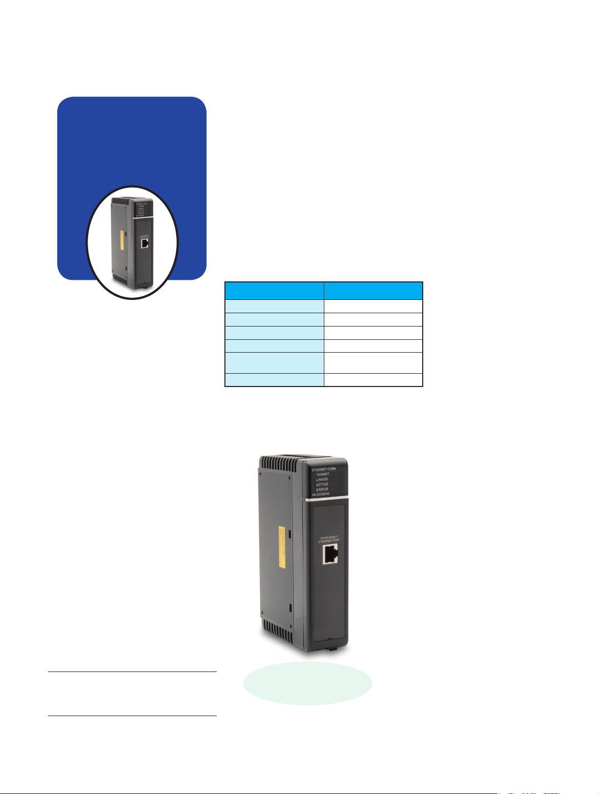
Ethernet Communication Modules
Simple connections
Ethernet
Communications
Module
H4-ECOM100 $510.00
Overview
Ethernet Communications Modules offer
features such as:
• High-speed peer-to-peer networking
of PLCs
• Fast updates with DirectSOFT Programming
Software
• High-performance access for Human
Machine Interface (HMI), ERP, MES or
other Windows-based software
• Industry standard ModbusTCP/IP
Client/Server Protocol
• Free SDK for custom drivers
• Easy setup
The Ethernet Communication Module
(ECOM) supports high-speed peer-topeer networking of PLCs. No longer are
you forced to designate a single PLC to be
the network master. Any PLC can initiate
communications with any other PLC. Link
your PLCs with PCs using industry standard Modbus TCP/IP protocol connected
through standard cables, hubs, and
repeaters. Or, use KEPSeverEX* I/O Server
to link to your favorite HMI/SCADA,
data historian, MES or ERP software
to DirectLOGIC PLCs. Our DataWorx
data collection software includes ECOM
drivers as well. DirectSOFT Programming
Software can be used to monitor or
update the program in any DirectLOGIC
PLC on the network.
* KEPSEvErEX may bE PurchaSEd from
KEPwarE and will SuPPort any EXiSting
aPPlicationS. (httPS://www.KEPwarE.com/
En-uS/ProductS/KEPSErvErEX)
Use Category 5 UTP cables or 62.5/125
ST-style fiber optic cables depending
on the requirements of your application. Inexpensive UTP cables can be
run up to 100 meters between nodes,
and fiber optic cables can be run up to
2,000 meters. Fiber optic cables virtually
eliminate electrical noise problems. Use
repeaters to extend distances and expand
the number of nodes.
Specifications H4-ECOM100
Communications
Data Transfer Rate
Link Distance
Ethernet Port
Ethernet Protocols
Power Consumption
10/100Base-T Ethernet
100Mbps max.
100 meters (328 ft)
RJ45
TCP/IP, IPX, MODBUS TCP/IP,
DHCP, HTML configuration
300mA @ 5VDC
H4-ECOM100
H4-ECOM100 supports the
Industry Standard Modbus TCP/IP
Client/Server Protocol
The
H4-ECOM100 IBox
communications
instructions
Over 40 communications IBox instructions are available when using the
H4-ECOM100 with D4-454 CPUs and
DirectSOFT6 programming software.
These easy-to-use instructions allow you
to:
• Enable/disable module DHCP
• Read/write module IP, Gateway and
Subnet Mask addresses
• Read/write module ID, Name and
Description
• Send E-mail messages
• Read/Write PLC memory to networked
Hx-ECOM100 modules
See the following page for example
communications IBox instructions.
tDL4-22
DL405 PLCs
1-800-633-0405
For the latest prices, please check AutomationDirect.com.
Ethernet Communication Modules
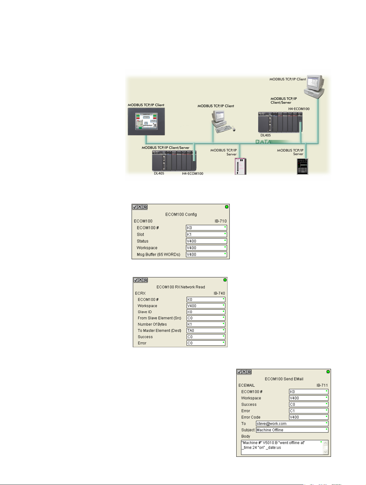
Modbus TCP/IP support
The H4-ECOM100 supports the industry
standard Modbus TCP/IP Client/Server
protocol in addition to the standard IP
and IPX protocols. This allows the DL405
PLC with an H4-ECOM100 module to
serve as a client (master) or as a server
(slave) on a Modbus TCP/IP Ethernet
network. The H4-ECOM100 can actively
issue Modbus commands to other nodes
or devices on the Modbus TCP/IP network
or simply respond to connected Modbus
TCP/IP clients.
PLC-to-PLC
communications
PLC-to-PLC or PLC to a Modbus TCP/IP
device communications can be accomplished using standard Read from Network
(RX) and Write to Network (WX) instructions (D4-454, all H4 series ECOMs and
all DirectSOFT versions). If you’re using our
DirectSOFT6 programming software with a
D4-454 PLC and an H4-ECOM100, you
can use fill-in-the-blank IBox instructions
to simplify your communications programming. The H4-ECOM100 supports the
ECOM Configuration IBox for use with
the ECRX and ECWX IBox instructions to
read/write to other ECOMs. H4 series
ECOM modules support the NETCFG
Configuration IBox for use with the NETRX
and NETWX IBox instructions to read/write
to other ECOM modules. The communications IBox instructions execute with built-in
interlocking to greatly simplify communications programming.
Modbus TCP/IP communications architecture
ECOM100 Configuration IBox
ECOM100 Read Network IBox
NetEdit3 software
NetEdit3 Software is installed with
DirectSOFT and it can be downloaded on the AutomationDirect.com
website. Use NetEdit3 to configure
the ECOM modules for your network.
Flexible addressing allows you to use
your choice of protocols and identifying methods. Assign each module
a number or a name or both. You
don’t have to use an IP address,
but you can if it’s necessary for your
network. NetEdit3 uses two protocols for PC-to-PLC communications:
IPX and TCP/IP. The NetEdit3 screen
displays all identifiers and troubleshooting information for each module
on the network. You can use NetEdit3
to adjust parameters for PLC-to-PLC
communications by clicking on
Advanced Settings. The network
identifiers can also be changed from
DirectSOFT Programming Software.
Choose your slot
The ECOM modules plug into any I/O slot
of any local DL405 I/O base. The module
maintains identification data, descriptive
information, and communication parameters for PLC-to-PLC communications in
flash memory. Disconnect power before
installing or removing any PLC module.
H4-ECOM100 has
e-mail capability!
The H4-ECOM100 Send EMail
(ECEMAIL) IBox instruction will allow the
module to behave as an e-mail client
and send an SMTP request to your SMTP
Server to send a specified e-mail message
to the e-mail addresses in the IBox’s To:
field. The Body: field allows you to embed
real-time data in your e-mail message.
The D4-454 CPUs and DirectSOFT6.1 or
later are required to use the IBox instructions.
www.automationdirect.com/dl405
ECOM100 Send EMail IBox
DL405 PLCs
tDL4-23

Check the Power Budget
For the latest prices, please check AutomationDirect.com.
Verify your power budget
requirements
Your I/O configuration choice can be
affected by the power requirements of the
I/O modules you choose. When determining the types and quantity of I/O
modules you will be using, it is important
to remember there is a limited amount of
power available from the power supply.
The chart on the opposite page indicates
the power supplied and used by each
DL405 device. The adjacent chart shows
an example of how to calculate the power
used by your particular system. These
two charts should make it easy for you to
determine if the devices you have chosen
fit within the power budget of your system
configuration.
If the I/O you have chosen exceeds the
maximum power available from the power
supply, you can resolve the problem by
shifting some of the modules to an expansion base or remote I/O base (if you are
using remote I/O).
Warning: It is extremely important to calculate the
power budget correctly. If you exceed the power
budget, the system may operate in an unpredictable
manner which may result in a risk of personal injury
or equipment damage.
Use ZIPLinks to reduce
power requirements
If your application requires a lot of relay
outputs, consider using the ZIPLink AC
or DC relay output modules. These
modules can switch high current (10A)
loads without putting a load on your base
power budget. Refer to Wiring System for
DL405 PLCs later in this section for more
information.
This logo is placed next to I/O modules
that are supported by the ZIPLink connection systems.
See the I/O module specifications at the
end of this section.
Calculating your power
usage
The following example shows how to
calculate the power budget for the DL405
system. The example is constructed around
a single 8-slot base using the devices
shown. It is recommended you construct a
similar table for each base in your system
A
Base Number
0
Device Type 5 VDC (mA)
External 24 VDC
Power (mA)
B CURRENT SUPPLIED
CPU/Expansion Unit
/Remote Slave
D4-454 CPU 3700 400
C CURRENT REQUIRED
SLOT 0
SLOT 1
SLOT 2
SLOT 3
SLOT 4
SLOT 5
SLOT 6
SLOT 7
D4-16ND2 +150 +0
D4-16ND2 +150 +0
F4-04DA +120 +100
D4-08NA +100 +0
D4-08NA +100 +0
D4-16TD2 +100 +0
D4-16TD2 +100 +0
D4-16TR +1000 +0
D OTHER
BASE
Handheld Programmer
E Maximum Current Required
F Remaining Current Available
1. Using a chart similar to the one above, fill in column 2.
2. Using the tables on the opposite page, enter the current supplied and used by each device (columns 3 and 4). Pay special attention to
the current supplied by the CPU, Expansion Unit, and Remote Slave since they differ. Devices which fall into the “Other” category (Row D)
are devices such as the Base and the Handheld programmer, which also have power requirements, but do not plug directly into the base.
3. Add the current used by the system devices (columns 3 and 4) starting with Slot 0 and put the total in the row labeled “maximum current required” (Row E).
4. Subtract the row labeled “Maximum current required” (Row E), from the row labeled “Current Supplied” (Row B). Place the difference in
the row labeled “Remaining Current Available” (Row F).
5. If “Maximum Current Required” is greater than “Current Supplied” in either column 3 or 4, the power budget will be exceeded. It will be
unsafe to use this configuration and you will need to restructure your I/O configuration. Note the auxiliary 24VDC power supply does not
need to supply all the external power. If you need more than the 400mA supplied, you can add an external 24VDC power supply. This will
help keep you within your power budget for external power.
D4-08B-1 +80 +0
D4-HPP-1 +320 +0
2820 100
3700-2820=880 400-100=300
.
DL405 CPU power supply specifications and power requirements
Specification AC Powered Units 24 VDC Powered Units
D4-454,
Part Numbers
Voltage Withstand (dielectric)
Insulation Resistance
Input Voltage Range
Maximum Inrush Current
Maximum Power
tDL4-16
D4-EX (expansion base unit),
D4-RS (remote slave unit)
1 minute @ 1,500 VAC between primary, secondary, field ground, and run relay
85-132 VAC (110V range)
170-264 VAC (220V range)
20A 20A
50VA 38W
DL405 PLCs
D4-454DC-1, D4-EXDC (expansion base unit)
> 10Mq at 500VDC
20-28 VDC (24VDC)
with less than 10% ripple
1-800-633-0405

Power Requirements
Power Supplied
CPUs/Remote Units/
Expansion Units
D4-454 CPU
D4-454DC-1
Power-consuming
Device
I/O Bases Analog Modules (continued)
D4-04B-1
D4-06B-1
D4-08B-1
DC Input Modules
D4-16ND2
D4-16ND2F
D4-32ND3-1
D4-64ND2
5 VDC Current
Supplied in mA
3100
3100
5V Current
Consumed
80
80
80
150
150
150
300 max.
24V Aux Power
Supplied in mA
400
NONE
Power Consumed
External 24VDC
Current Required
NONE
NONE
NONE
NONE
NONE
NONE
NONE
CPUs/Remote Units/
Expansion Units
D4-EX
D4-EXDC
D4-RS
H4-EBC
Power-consuming
Device
F4-16AD-1
F4-16AD-2
F4-04DA-1
F4-04DA-2
F4-04DAS-1
F4-08DA-1
F4-08DA-2
F4-16DA-1
F4-16DA-2
F4-08RTD
F4-08THM-n
F4-08THM
Remote I/O
For the latest prices, please check AutomationDirect.com.
5V Current Supplied
in mA
4000
4000
3700
3470
5V Current
Consumed
75
75
70
90
60
90
80
90
80
80
120
110
24V Aux Power
Supplied in mA
400
NONE
400
400
External 24VDC
Current Required
100
100
75+20 per circuit
90
60 per circuit
100+20 per circuit
150
100+20 per circuit
25 max.
NONE
50
60
AC Input Modules
H4-ERM100
D4-08NA
D4-16NA
100
150
NONE
NONE
H4-ERM-F
D4-RM
AC/DC Input Modules
D4-16NE3 150 NONE
DC Output Modules
D4-16TD1
D4-16TD2
D4-32TD1
D4-32TD2
D4-64TD1
200
400
250
350
800
125
NONE
140
120 (4A max
including loads)
NONE
Communications and Networking
H4-ECOM100
D4-DCM
F4-MAS-MB
CoProcessors
F4-CP128-1 305 NONE
AC Output Modules
D4-08TA
D4-16TA
Relay Output Modules
D4-08TR
F4-08TRS-1
F4-08TRS-2
D4-16TR
250
450
550
575
575
1000
NONE
NONE
NONE
NONE
NONE
NONE
Specialty Modules
H4-CTRIO
D4-16SIM
F4-4LTC
Analog Modules Programming
F4-04AD
F4-04ADS
F4-08AD
150
370
75
100
120
90
D4-HPP-1 (Handheld Prog.) 320 NONE
Operator Interface
DV-1000 150 NONE
C-more Micro-Graphic 210 NONE
320(300)
450
300
300
500
235
400
150
280
NONE
NONE
NONE
NONE
NONE
NONE
NONE
NONE
75
www.automationdirect.com/dl405
DL405 PLCs
tDL4-17
 Loading...