

Hospal Prisma Fluid Management System Service manual

®
PRISMA System
An integrated system for continuous fluid
management, renal replacement therapies and
therapeutic plasma exchange
Service Manual
For software version R03.10
GAMBRO DASCO S.p.A.
Via Modenese, 66
41036 Medolla (MO) -Italy
Reorder Service Code 6983928 Rev. A
Manufacturing P/N 9032168000 Rev. A
2006/09

Manufactured by:
GAMBRO DASCO S.p.A., Via Modenese 66, 41036 MEDOLLA (M O) Italy
Questions or comments about this publication can be directed to your local representative or to
manufacturer.
© 1992-1996, 1998 Gambro Inc. (unpublished), 200 0-2001 Gambr o Dasco SpA (unpublished), 2001-2006
Gambro Lundia AB (unpublished)
PRISMA® is a trademark of GAMBRO Inc. registered in the United States, Argentina, Chile, Mexico, and
Uruguay.
GAMBRO® is a registered trademark of GAMBRO LUNDIA AB.
HOSPAL® is a registered trademark of GAMBRO HOSPAL SWITZERLAND Ltd.
The PRISMA® machine is protected by one or more of the following patents:
- U.S. patents: 4861242, 5644402, 5722399, 5679245, 5776345, 5910252, 5762805,
5211849, 5394732;
- European patents: 0611228, 0678301, 0701830, 0829265, 0706044, 0607301, 0643301;
- GB patents: 2208897;
- Canadian patents: 1284598, 2115414, 2303714, 2119375;
- Japanese patents: 1772297, 2823513, 3690846, 3591864, 3413412, 3140781;
- German patents: 3828123;
- French patents: 2619604, 2724321, 2725522;
- Italian patents: 122378 1.

Preface
Indications . . . . . . . . . . . . . . . . . . . . . . . . . . . . . . . . . . . . . . . . . . . . . . . . . . . . xiii
Contraindications . . . . . . . . . . . . . . . . . . . . . . . . . . . . . . . . . . . . . . . . . . . . . . xiii
System Components . . . . . . . . . . . . . . . . . . . . . . . . . . . . . . . . . . . . . . . . . . . . xiii
Control Unit . . . . . . . . . . . . . . . . . . . . . . . . . . . . . . . . . . . . . . . . . . . . . . . xiii
Set . . . . . . . . . . . . . . . . . . . . . . . . . . . . . . . . . . . . . . . . . . . . . . . . . . . . . . xiii
Where to Find Information About the PRISMA System . . . . . . . . . . . . . . . . xiv
Operator’s Manual . . . . . . . . . . . . . . . . . . . . . . . . . . . . . . . . . . . . . . . . . xiv
On-line Instructions . . . . . . . . . . . . . . . . . . . . . . . . . . . . . . . . . . . . . . . . xiv
PRISMA Set Instructions for Use . . . . . . . . . . . . . . . . . . . . . . . . . . . . . xiv
Warnings . . . . . . . . . . . . . . . . . . . . . . . . . . . . . . . . . . . . . . . . . . . . . . . . . . . . xiv
Precautions . . . . . . . . . . . . . . . . . . . . . . . . . . . . . . . . . . . . . . . . . . . . . . . . . . xix
Disclaimer . . . . . . . . . . . . . . . . . . . . . . . . . . . . . . . . . . . . . . . . . . . . . . . . . . . xxiii
Service Information . . . . . . . . . . . . . . . . . . . . . . . . . . . . . . . . . . . . . . . . . . . . xxiv
Disposal of Lithium Energy Cell . . . . . . . . . . . . . . . . . . . . . . . . . . . . . . . . . . xxvi
Disposal of Packaging Material . . . . . . . . . . . . . . . . . . . . . . . . . . . . . . . . . . . xxvi
Warranty . . . . . . . . . . . . . . . . . . . . . . . . . . . . . . . . . . . . . . . . . . . . . . . . . . . . xxvi
Chapter 1: Introduction
Introduction . . . . . . . . . . . . . . . . . . . . . . . . . . . . . . . . . . . . . . . . . . . . . . . . . . 1-1
Blood Access . . . . . . . . . . . . . . . . . . . . . . . . . . . . . . . . . . . . . . . . . . . . . 1-1
PRISMA Control Unit Functions . . . . . . . . . . . . . . . . . . . . . . . . . . . . . . 1-1
Therapy Overview . . . . . . . . . . . . . . . . . . . . . . . . . . . . . . . . . . . . . . . . . . . . . 1-1
PRISMA Therapy Options . . . . . . . . . . . . . . . . . . . . . . . . . . . . . . . . . . . 1-2
Mechanisms of Therapy . . . . . . . . . . . . . . . . . . . . . . . . . . . . . . . . . . . . 1-2
PRISMA Control Unit . . . . . . . . . . . . . . . . . . . . . . . . . . . . . . . . . . . . . . . . . . 1-4
Front Panel . . . . . . . . . . . . . . . . . . . . . . . . . . . . . . . . . . . . . . . . . . . . . . 1-4
Ultrafiltration . . . . . . . . . . . . . . . . . . . . . . . . . . . . . . . . . . . . . . . . . . . 1-2
Hemofiltration . . . . . . . . . . . . . . . . . . . . . . . . . . . . . . . . . . . . . . . . . . 1-2
Hemodialysis . . . . . . . . . . . . . . . . . . . . . . . . . . . . . . . . . . . . . . . . . . 1-2
Hemodiafiltration . . . . . . . . . . . . . . . . . . . . . . . . . . . . . . . . . . . . . . . 1-3
Therapeutic Plasma Exchange . . . . . . . . . . . . . . . . . . . . . . . . . . . . 1-3
Status Lights . . . . . . . . . . . . . . . . . . . . . . . . . . . . . . . . . . . . . . . . . . 1-4
Display . . . . . . . . . . . . . . . . . . . . . . . . . . . . . . . . . . . . . . . . . . . . . . . 1-5
Pressure Sensor Housings . . . . . . . . . . . . . . . . . . . . . . . . . . . . . . . 1-5
Peristaltic Pumps . . . . . . . . . . . . . . . . . . . . . . . . . . . . . . . . . . . . . . . 1-5
Cartridge Carrier . . . . . . . . . . . . . . . . . . . . . . . . . . . . . . . . . . . . . . . 1-6
Blood Pump . . . . . . . . . . . . . . . . . . . . . . . . . . . . . . . . . . . . . . . . . . . 1-6
Air Bubble Detector . . . . . . . . . . . . . . . . . . . . . . . . . . . . . . . . . . . . . 1-6
Pump Raceway . . . . . . . . . . . . . . . . . . . . . . . . . . . . . . . . . . . . . . . . 1-6
Dialysate Pump . . . . . . . . . . . . . . . . . . . . . . . . . . . . . . . . . . . . . . . . 1-6
Return Line Clamp . . . . . . . . . . . . . . . . . . . . . . . . . . . . . . . . . . . . . . 1-6
Tubing Guides . . . . . . . . . . . . . . . . . . . . . . . . . . . . . . . . . . . . . . . . . 1-6
Corner Hooks . . . . . . . . . . . . . . . . . . . . . . . . . . . . . . . . . . . . . . . . . . 1-6
Blood Leak Detector . . . . . . . . . . . . . . . . . . . . . . . . . . . . . . . . . . . . . 1-6
Syringe Pump Assembly . . . . . . . . . . . . . . . . . . . . . . . . . . . . . . . . . 1-6
PRISMA® System Service Manual i

Rotor . . . . . . . . . . . . . . . . . . . . . . . . . . . . . . . . . . . . . . . . . . . . . . . . 1-7
Effluent Pump . . . . . . . . . . . . . . . . . . . . . . . . . . . . . . . . . . . . . . . . . . 1-7
Bottom Panel . . . . . . . . . . . . . . . . . . . . . . . . . . . . . . . . . . . . . . . . . . . . . 1-7
Scales . . . . . . . . . . . . . . . . . . . . . . . . . . . . . . . . . . . . . . . . . . . . . . . 1-7
Scale Hook Assemblies . . . . . . . . . . . . . . . . . . . . . . . . . . . . . . . . . . 1-7
Right Side Panel . . . . . . . . . . . . . . . . . . . . . . . . . . . . . . . . . . . . . . . . . . 1-7
Power Switch . . . . . . . . . . . . . . . . . . . . . . . . . . . . . . . . . . . . . . . . . . 1-7
Left Side Panel . . . . . . . . . . . . . . . . . . . . . . . . . . . . . . . . . . . . . . . . . . . 1-7
Fan . . . . . . . . . . . . . . . . . . . . . . . . . . . . . . . . . . . . . . . . . . . . . . . . . . 1-7
Rear Panel . . . . . . . . . . . . . . . . . . . . . . . . . . . . . . . . . . . . . . . . . . . . . . 1-7
Controller CCA . . . . . . . . . . . . . . . . . . . . . . . . . . . . . . . . . . . . . . . . . 1-8
Monitor CCA . . . . . . . . . . . . . . . . . . . . . . . . . . . . . . . . . . . . . . . . . . . 1-8
Detector CCA . . . . . . . . . . . . . . . . . . . . . . . . . . . . . . . . . . . . . . . . . . 1-8
Hour Meter . . . . . . . . . . . . . . . . . . . . . . . . . . . . . . . . . . . . . . . . . . . . 1-9
Power Supply . . . . . . . . . . . . . . . . . . . . . . . . . . . . . . . . . . . . . . . . . . 1-9
Serial Communication Port . . . . . . . . . . . . . . . . . . . . . . . . . . . . . . . 1-9
Power Distribution CCA . . . . . . . . . . . . . . . . . . . . . . . . . . . . . . . . . . 1-9
Fuses . . . . . . . . . . . . . . . . . . . . . . . . . . . . . . . . . . . . . . . . . . . . . . . . 1-9
Power Entry Module . . . . . . . . . . . . . . . . . . . . . . . . . . . . . . . . . . . . . 1-9
Automatic Reposition System (ARPS) . . . . . . . . . . . . . . . . . . . . . . . 1-9
Driver CCA . . . . . . . . . . . . . . . . . . . . . . . . . . . . . . . . . . . . . . . . . . . . 1-9
Analog CCA . . . . . . . . . . . . . . . . . . . . . . . . . . . . . . . . . . . . . . . . . . . 1-9
Jumpers Configuration . . . . . . . . . . . . . . . . . . . . . . . . . . . . . . . . . . . . 1-10
Chapter 2: Continuous Renal Replacement and Therapeutic Plasma
Exchange Therapies
CRRT System Overview . . . . . . . . . . . . . . . . . . . . . . . . . . . . . . . . . . . . . . . . 2-3
Interactive Display . . . . . . . . . . . . . . . . . . . . . . . . . . . . . . . . . . . . . . 2-4
User-controllable Settings . . . . . . . . . . . . . . . . . . . . . . . . . . . . . . . . 2-4
Default Values . . . . . . . . . . . . . . . . . . . . . . . . . . . . . . . . . . . . . 2-4
Current Values . . . . . . . . . . . . . . . . . . . . . . . . . . . . . . . . . . . . . 2-5
Pumps . . . . . . . . . . . . . . . . . . . . . . . . . . . . . . . . . . . . . . . . . . . . . . . . . . 2-5
Flow Rates and Anticoagulant Settings . . . . . . . . . . . . . . . . . . . . . . . . . 2-5
Adjusting the Flow Rates and Anticoagulant Settings . . . . . . . . . . . 2-6
Patient Fluid Removal Rate . . . . . . . . . . . . . . . . . . . . . . . . . . . . . . . 2-6
Calculating the Desired Patient Fluid Removal Rate . . . . . . . . 2-6
Adjusting the Patient Fluid Removal Rate . . . . . . . . . . . . . . . . 2-6
Machine Control of Patient Fluid Removal Rate . . . . . . . . . . . 2-7
Setting the "Excess Pt. Fluid Loss or Gain" Safety Limit . . . . . 2-7
Fluid Balance . . . . . . . . . . . . . . . . . . . . . . . . . . . . . . . . . . . . . . . . . . . . . 2-7
Actual Patient Fluid Removed . . . . . . . . . . . . . . . . . . . . . . . . . . . . . 2-7
Measuring Actual Patient Fluid Removed . . . . . . . . . . . . . . . . 2-7
Viewing Actual Patient Fluid Removed . . . . . . . . . . . . . . . . . . 2-8
I/O Data . . . . . . . . . . . . . . . . . . . . . . . . . . . . . . . . . . . . . . . . . . . . . . 2-8
Treatment History Data . . . . . . . . . . . . . . . . . . . . . . . . . . . . . . . . . . . . . 2-9
I/O History . . . . . . . . . . . . . . . . . . . . . . . . . . . . . . . . . . . . . . . . . . . . 2-9
Events History . . . . . . . . . . . . . . . . . . . . . . . . . . . . . . . . . . . . . . . . . 2-9
History Data After a Treatment . . . . . . . . . . . . . . . . . . . . . . . . . . . 2-10
History Data During a Power Loss . . . . . . . . . . . . . . . . . . . . . . . . . 2-10
Alarm Safety System . . . . . . . . . . . . . . . . . . . . . . . . . . . . . . . . . . . . . . 2-10
Monitoring Systems . . . . . . . . . . . . . . . . . . . . . . . . . . . . . . . . . . . . . . . 2-10
Pressure . . . . . . . . . . . . . . . . . . . . . . . . . . . . . . . . . . . . . . . . . . . . . 2-10
ii PRISMA® System Service Manual

Blood Leak . . . . . . . . . . . . . . . . . . . . . . . . . . . . . . . . . . . . . . . . . . . 2-10
Air Bubble . . . . . . . . . . . . . . . . . . . . . . . . . . . . . . . . . . . . . . . . . . . . 2-10
CRRT Operation . . . . . . . . . . . . . . . . . . . . . . . . . . . . . . . . . . . . . . . . . . . . . 2-11
Startup . . . . . . . . . . . . . . . . . . . . . . . . . . . . . . . . . . . . . . . . . . . . . . . . . 2-11
Control and Navigation . . . . . . . . . . . . . . . . . . . . . . . . . . . . . . . . . . . . 2-11
Screen Layout . . . . . . . . . . . . . . . . . . . . . . . . . . . . . . . . . . . . . . . . . . . 2-11
Operating Modes . . . . . . . . . . . . . . . . . . . . . . . . . . . . . . . . . . . . . . . . . 2-12
Setup Mode . . . . . . . . . . . . . . . . . . . . . . . . . . . . . . . . . . . . . . . . . . 2-12
Standby Mode . . . . . . . . . . . . . . . . . . . . . . . . . . . . . . . . . . . . . . . . 2-15
Run Mode . . . . . . . . . . . . . . . . . . . . . . . . . . . . . . . . . . . . . . . . . . . . 2-16
End Mode . . . . . . . . . . . . . . . . . . . . . . . . . . . . . . . . . . . . . . . . . . . . 2-17
Change Set Procedure . . . . . . . . . . . . . . . . . . . . . . . . . . . . . . 2-17
End Treatment Procedure . . . . . . . . . . . . . . . . . . . . . . . . . . . 2-18
Temporary Disconnection Procedure . . . . . . . . . . . . . . . . . . . 2-19
Custom Mode . . . . . . . . . . . . . . . . . . . . . . . . . . . . . . . . . . . . . . . . . 2-20
User-controllable Settings . . . . . . . . . . . . . . . . . . . . . . . . . . . . . . . . . . 2-20
Anticoagulant Syringe Installation Proced ur e . . . . . . . . . . . . . . . . . . . 2-23
Initial Syringe Installation . . . . . . . . . . . . . . . . . . . . . . . . . . . . . . . . 2-23
Changing the Syringe During Treatment . . . . . . . . . . . . . . . . . . . . 2-24
Change Bags Function . . . . . . . . . . . . . . . . . . . . . . . . . . . . . . . . . . . . 2-24
Control Unit Actions . . . . . . . . . . . . . . . . . . . . . . . . . . . . . . . . . . . . 2-25
Changing a Bag During Treatment . . . . . . . . . . . . . . . . . . . . . . . . 2-25
Pressure Monitoring . . . . . . . . . . . . . . . . . . . . . . . . . . . . . . . . . . . . . . . . . . 2-25
Pressure Monitoring Components . . . . . . . . . . . . . . . . . . . . . . . . . . . . 2-26
Pressures During Operation . . . . . . . . . . . . . . . . . . . . . . . . . . . . . . . . 2-26
Extreme Pressure Limits . . . . . . . . . . . . . . . . . . . . . . . . . . . . . . . . . . . 2-27
Pressure Operating Points . . . . . . . . . . . . . . . . . . . . . . . . . . . . . . . . . 2-28
Initial Values . . . . . . . . . . . . . . . . . . . . . . . . . . . . . . . . . . . . . . . . . . 2-28
Subsequent Values . . . . . . . . . . . . . . . . . . . . . . . . . . . . . . . . . . . . 2-28
Pressure Trending Limits . . . . . . . . . . . . . . . . . . . . . . . . . . . . . . . . 2-29
“Cannot Detect Disconnection” Limits . . . . . . . . . . . . . . . . . . . . . . 2-29
Software-calculated Pressures . . . . . . . . . . . . . . . . . . . . . . . . . . . . . . 2-29
Transmembrane Pressure (TMP) . . . . . . . . . . . . . . . . . . . . . . . . . 2-29
Filter Pressure Drop (DP Filter) . . . . . . . . . . . . . . . . . . . . . . . . . . . 2-30
PRISMA TPE Set . . . . . . . . . . . . . . . . . . . . . . . . . . . . . . . . . . . . . . . . . . . . 2-31
System Overview with TPE . . . . . . . . . . . . . . . . . . . . . . . . . . . . . . . . . . . . . 2-33
Communicating With the PRISMA Control Unit . . . . . . . . . . . . . . . . . 2-33
Interactive Display . . . . . . . . . . . . . . . . . . . . . . . . . . . . . . . . . . . . . 2-33
User-controllable Settings . . . . . . . . . . . . . . . . . . . . . . . . . . . . . . . 2-34
Default Values . . . . . . . . . . . . . . . . . . . . . . . . . . . . . . . . . . . . 2-34
Current Values . . . . . . . . . . . . . . . . . . . . . . . . . . . . . . . . . . . . 2-34
Pumps . . . . . . . . . . . . . . . . . . . . . . . . . . . . . . . . . . . . . . . . . . . . . . . . . 2-34
TPE Prescription, Flow Rates, and Anticoagulant Settings . . . . . . . . . 2-35
Adjusting the TPE Prescription, Flow Rates, and Anticoagulant
Settings . . . . . . . . . . . . . . . . . . . . . . . . . . . . . . . . . . . . . . . . . . . . . 2-35
Patient Plasma Loss Rate . . . . . . . . . . . . . . . . . . . . . . . . . . . . . . . 2-35
Software Calculations of Target Patient Plasma Loss . . . . . . 2-36
Setting the Patient Plasma Loss Rate to Achieve Prescribed
Target Loss . . . . . . . . . . . . . . . . . . . . . . . . . . . . . . . . . . . . . . 2-36
Setting the "Excess Pt. Fluid Loss or Gain" Safety Limit . . . . 2-36
Plasma Balance . . . . . . . . . . . . . . . . . . . . . . . . . . . . . . . . . . . . . . . . . 2-37
Actual Patient Plasma Loss . . . . . . . . . . . . . . . . . . . . . . . . . . . . . . 2-37
Measuring Actual Patient Plasma Loss . . . . . . . . . . . . . . . . . 2-37
Viewing Actual Patient Plasma Loss . . . . . . . . . . . . . . . . . . . 2-37
PRISMA® System Service Manual iii

Treatment Data . . . . . . . . . . . . . . . . . . . . . . . . . . . . . . . . . . . . . . . 2-37
Treatment History Data . . . . . . . . . . . . . . . . . . . . . . . . . . . . . . . . . . . . 2-38
Treatment History . . . . . . . . . . . . . . . . . . . . . . . . . . . . . . . . . . . . . . 2-38
Events History . . . . . . . . . . . . . . . . . . . . . . . . . . . . . . . . . . . . . . . . 2-38
History Data After a Treatment . . . . . . . . . . . . . . . . . . . . . . . . . . . 2-39
History Data During a Power Loss . . . . . . . . . . . . . . . . . . . . . . . . . 2-39
Alarm Safety System . . . . . . . . . . . . . . . . . . . . . . . . . . . . . . . . . . . . . . 2-39
Monitoring Systems . . . . . . . . . . . . . . . . . . . . . . . . . . . . . . . . . . . . . . . 2-39
Pressure . . . . . . . . . . . . . . . . . . . . . . . . . . . . . . . . . . . . . . . . . . . . . 2-39
Blood Leak . . . . . . . . . . . . . . . . . . . . . . . . . . . . . . . . . . . . . . . . . . . 2-39
Air Bubble . . . . . . . . . . . . . . . . . . . . . . . . . . . . . . . . . . . . . . . . . . . . 2-40
TPE Operation . . . . . . . . . . . . . . . . . . . . . . . . . . . . . . . . . . . . . . . . . . . . . . 2-40
Startup . . . . . . . . . . . . . . . . . . . . . . . . . . . . . . . . . . . . . . . . . . . . . . . . . 2-40
Control and Navigation . . . . . . . . . . . . . . . . . . . . . . . . . . . . . . . . . . . . 2-40
Screen Layout . . . . . . . . . . . . . . . . . . . . . . . . . . . . . . . . . . . . . . . . . . . 2-41
Operating Modes . . . . . . . . . . . . . . . . . . . . . . . . . . . . . . . . . . . . . . . . . 2-41
Setup Mode . . . . . . . . . . . . . . . . . . . . . . . . . . . . . . . . . . . . . . . . . . 2-41
SPECIAL PROCEDURE WHEN USING THE ACCESSORY
SP394 WITH THE PRISMA SYSTEM IN TPE MODE . . . . . . 2-42
Standby Mode . . . . . . . . . . . . . . . . . . . . . . . . . . . . . . . . . . . . . . . . 2-45
Run Mode . . . . . . . . . . . . . . . . . . . . . . . . . . . . . . . . . . . . . . . . . . . . 2-46
End Mode . . . . . . . . . . . . . . . . . . . . . . . . . . . . . . . . . . . . . . . . . . . . 2-47
Change Set Procedure . . . . . . . . . . . . . . . . . . . . . . . . . . . . . . 2-47
End Treatment Procedure . . . . . . . . . . . . . . . . . . . . . . . . . . . 2-48
Temporary Disconnection Procedure . . . . . . . . . . . . . . . . . . . 2-49
Custom Mode . . . . . . . . . . . . . . . . . . . . . . . . . . . . . . . . . . . . . . . . . . . 2-50
User-controllable Settings . . . . . . . . . . . . . . . . . . . . . . . . . . . . . . . . . . 2-50
Anticoagulant Syringe Installation Proced ur e . . . . . . . . . . . . . . . . . . . 2-53
Initial Syringe Installation . . . . . . . . . . . . . . . . . . . . . . . . . . . . . . . . 2-53
Changing the Syringe During Treatment . . . . . . . . . . . . . . . . . . . . 2-54
Change Bags Function . . . . . . . . . . . . . . . . . . . . . . . . . . . . . . . . . . . . 2-54
Control Unit Actions . . . . . . . . . . . . . . . . . . . . . . . . . . . . . . . . . . . . 2-55
Changing a Bag During Treatment . . . . . . . . . . . . . . . . . . . . . . . . 2-55
Pressure Monitoring . . . . . . . . . . . . . . . . . . . . . . . . . . . . . . . . . . . . . . . . . . 2-55
Pressure Monitoring Components . . . . . . . . . . . . . . . . . . . . . . . . . . . . 2-56
Pressures During Operation . . . . . . . . . . . . . . . . . . . . . . . . . . . . . . . . 2-56
Pressure Operating Points . . . . . . . . . . . . . . . . . . . . . . . . . . . . . . . . . 2-58
Initial Values . . . . . . . . . . . . . . . . . . . . . . . . . . . . . . . . . . . . . . . . . . 2-58
Subsequent Values . . . . . . . . . . . . . . . . . . . . . . . . . . . . . . . . . . . . 2-58
Pressure Trending Limits . . . . . . . . . . . . . . . . . . . . . . . . . . . . . . . . 2-59
“Cannot Detect Disconnection” Limits . . . . . . . . . . . . . . . . . . . . . . . . . 2-59
Software-calculated Pressures . . . . . . . . . . . . . . . . . . . . . . . . . . . . . . 2-59
Access Transmembrane Pressure (TMPa) . . . . . . . . . . . . . . . . . . 2-59
Plasmafilter Pressure Drop
(DP Filter) . . . . . . . . . . . . . . . . . . . . . . 2-60
Chapter 3: Electronic Description
Power System . . . . . . . . . . . . . . . . . . . . . . . . . . . . . . . . . . . . . . . . . . . . . . . . 3-2
Monitor CCA . . . . . . . . . . . . . . . . . . . . . . . . . . . . . . . . . . . . . . . . . . . . . . . . . 3-3
Display . . . . . . . . . . . . . . . . . . . . . . . . . . . . . . . . . . . . . . . . . . . . . . . . . . 3-4
Monitor CCA Display Driver . . . . . . . . . . . . . . . . . . . . . . . . . . . . . . . . . 3-4
Speaker . . . . . . . . . . . . . . . . . . . . . . . . . . . . . . . . . . . . . . . . . . . . . . . . . 3-5
COM 2 (RS-232 Serial Interface Port) . . . . . . . . . . . . . . . . . . . . . . . . . . 3-6
iv PRISMA® System Service Manual

Monitor Watch Dog . . . . . . . . . . . . . . . . . . . . . . . . . . . . . . . . . . . . . . . . 3-7
Power Fail . . . . . . . . . . . . . . . . . . . . . . . . . . . . . . . . . . . . . . . . . . . . . . . 3-8
Controller CCA . . . . . . . . . . . . . . . . . . . . . . . . . . . . . . . . . . . . . . . . . . . . . . . 3-9
Touchscreen . . . . . . . . . . . . . . . . . . . . . . . . . . . . . . . . . . . . . . . . . . . . 3-10
Touchscreen Softkeys . . . . . . . . . . . . . . . . . . . . . . . . . . . . . . . . . . . . . 3-10
Controller Watch Dog . . . . . . . . . . . . . . . . . . . . . . . . . . . . . . . . . . . . . 3-11
Detector CCA . . . . . . . . . . . . . . . . . . . . . . . . . . . . . . . . . . . . . . . . . . . . . . . 3-12
Ultrasonic Air Bubble Detector (UABD) . . . . . . . . . . . . . . . . . . . . . . . . 3-13
Ultrasonic Oscillator and Transmitter Output . . . . . . . . . . . . . . . . . 3-13
Ultrasonic Receiver Output . . . . . . . . . . . . . . . . . . . . . . . . . . . . . . 3-14
Blood Leak Detector (BLD) . . . . . . . . . . . . . . . . . . . . . . . . . . . . . . . . . 3-15
Operation . . . . . . . . . . . . . . . . . . . . . . . . . . . . . . . . . . . . . . . . . . . . 3-15
Normalization . . . . . . . . . . . . . . . . . . . . . . . . . . . . . . . . . . . . . . . . . 3-16
Automatic Reposition System (ARPS) . . . . . . . . . . . . . . . . . . . . . . . . . . . . 3-17
Reposition Sequence . . . . . . . . . . . . . . . . . . . . . . . . . . . . . . . . . . . . . 3-17
Effluent (TPE Only), Filter, Return Pressure Pods . . . . . . . . . . . . . 3-18
Effluent (CRRT Only), Access Pressure Pods . . . . . . . . . . . . . . . . 3-18
ARPS Electronic Description . . . . . . . . . . . . . . . . . . . . . . . . . . . . . . . . 3-19
Driver CCA . . . . . . . . . . . . . . . . . . . . . . . . . . . . . . . . . . . . . . . . . . . . . . . . . 3-20
Peristaltic Pumps . . . . . . . . . . . . . . . . . . . . . . . . . . . . . . . . . . . . . . . . . 3-21
Pump Circuits . . . . . . . . . . . . . . . . . . . . . . . . . . . . . . . . . . . . . . . . . 3-21
Return Line Clamp . . . . . . . . . . . . . . . . . . . . . . . . . . . . . . . . . . . . . . . 3-22
Syringe Pump . . . . . . . . . . . . . . . . . . . . . . . . . . . . . . . . . . . . . . . . . . . 3-23
Cartridge Loader . . . . . . . . . . . . . . . . . . . . . . . . . . . . . . . . . . . . . . . . . 3-23
Status Lights and Fan . . . . . . . . . . . . . . . . . . . . . . . . . . . . . . . . . . . . . 3-24
Lights . . . . . . . . . . . . . . . . . . . . . . . . . . . . . . . . . . . . . . . . . . . . . . . 3-24
Fan . . . . . . . . . . . . . . . . . . . . . . . . . . . . . . . . . . . . . . . . . . . . . . . . . 3-24
Analog CCA . . . . . . . . . . . . . . . . . . . . . . . . . . . . . . . . . . . . . . . . . . . . . . . . 3-25
Pressure Sensors . . . . . . . . . . . . . . . . . . . . . . . . . . . . . . . . . . . . . . . . 3-26
Scale Assemblies (Weight Transducer) . . . . . . . . . . . . . . . . . . . . . . . 3-27
LVDT Scale . . . . . . . . . . . . . . . . . . . . . . . . . . . . . . . . . . . . . . . . . . 3-27
Load Cell Scale . . . . . . . . . . . . . . . . . . . . . . . . . . . . . . . . . . . . . . . 3-28
Return Line Clamp Position Sensor . . . . . . . . . . . . . . . . . . . . . . . . . . 3-29
Chapter 4: Software Description
Power Up . . . . . . . . . . . . . . . . . . . . . . . . . . . . . . . . . . . . . . . . . . . . . . . . . . . 4-1
Periodic Self-test . . . . . . . . . . . . . . . . . . . . . . . . . . . . . . . . . . . . . . . . . . 4-2
Alarm Monitoring During the Periodic Self-test . . . . . . . . . . . . . . . . 4-2
Subtests . . . . . . . . . . . . . . . . . . . . . . . . . . . . . . . . . . . . . . . . . . . . . . 4-2
Macro Bubble Detector Test . . . . . . . . . . . . . . . . . . . . . . . . . . . 4-3
Micro Bubble Test . . . . . . . . . . . . . . . . . . . . . . . . . . . . . . . . . . 4-3
UABD Trouble Test . . . . . . . . . . . . . . . . . . . . . . . . . . . . . . . . . 4-3
24 Volt Test . . . . . . . . . . . . . . . . . . . . . . . . . . . . . . . . . . . . . . . 4-3
Blood Leak Detector Test . . . . . . . . . . . . . . . . . . . . . . . . . . . . . 4-3
Pressure Sensor Test . . . . . . . . . . . . . . . . . . . . . . . . . . . . . . . . 4-3
Failure of the Periodic Self-test . . . . . . . . . . . . . . . . . . . . . . . . . . . . 4-3
Prime . . . . . . . . . . . . . . . . . . . . . . . . . . . . . . . . . . . . . . . . . . . . . . . . . . . 4-3
Prime Test . . . . . . . . . . . . . . . . . . . . . . . . . . . . . . . . . . . . . . . . . . . . 4-4
Blood Leak Detector Normalization and Test . . . . . . . . . . . . . . 4-4
TMPa Calibration (TPE Therapy Only) . . . . . . . . . . . . . . . . . . . 4-4
Modified Periodic Self-test . . . . . . . . . . . . . . . . . . . . . . . . . . . . 4-4
PRISMA Set Recognition Test . . . . . . . . . . . . . . . . . . . . . . . . . 4-5
PRISMA® System Service Manual v

SCUF Priming Sequence . . . . . . . . . . . . . . . . . . . . . . . . . . . . . . . . . 4-6
CVVH Priming Sequence . . . . . . . . . . . . . . . . . . . . . . . . . . . . . . . . . 4-7
CVVHD Priming Sequence . . . . . . . . . . . . . . . . . . . . . . . . . . . . . . . 4-8
CVVHDF Priming Sequence . . . . . . . . . . . . . . . . . . . . . . . . . . . . . . 4-9
TPE Priming Sequence . . . . . . . . . . . . . . . . . . . . . . . . . . . . . . . . . 4-10
Service Mode . . . . . . . . . . . . . . . . . . . . . . . . . . . . . . . . . . . . . . . . . . . 4-11
Calibrate . . . . . . . . . . . . . . . . . . . . . . . . . . . . . . . . . . . . . . . . . . . . . 4-11
Scales . . . . . . . . . . . . . . . . . . . . . . . . . . . . . . . . . . . . . . . . . . . 4-11
Pressures . . . . . . . . . . . . . . . . . . . . . . . . . . . . . . . . . . . . . . . . 4-11
Diagnose . . . . . . . . . . . . . . . . . . . . . . . . . . . . . . . . . . . . . . . . . . . . 4-12
Pumps . . . . . . . . . . . . . . . . . . . . . . . . . . . . . . . . . . . . . . . . . . 4-12
Scales . . . . . . . . . . . . . . . . . . . . . . . . . . . . . . . . . . . . . . . . . . . 4-12
Pressures . . . . . . . . . . . . . . . . . . . . . . . . . . . . . . . . . . . . . . . . 4-12
Lights and Tones . . . . . . . . . . . . . . . . . . . . . . . . . . . . . . . . . . 4-12
Air Detector . . . . . . . . . . . . . . . . . . . . . . . . . . . . . . . . . . . . . . 4-12
Syringe Pump . . . . . . . . . . . . . . . . . . . . . . . . . . . . . . . . . . . . . 4-12
Clamp . . . . . . . . . . . . . . . . . . . . . . . . . . . . . . . . . . . . . . . . . . . 4-12
Blood Leak Detector . . . . . . . . . . . . . . . . . . . . . . . . . . . . . . . . 4-12
Load/Unload . . . . . . . . . . . . . . . . . . . . . . . . . . . . . . . . . . . . . . 4-13
Automatic Reposition System . . . . . . . . . . . . . . . . . . . . . . . . 4-13
Service - Internal Functions . . . . . . . . . . . . . . . . . . . . . . . . . . 4-13
Chapter 5: Service Screens and Calibration
PRISMA Service Screens . . . . . . . . . . . . . . . . . . . . . . . . . . . . . . . . . . . . . . . 5-1
Service Mode Screen . . . . . . . . . . . . . . . . . . . . . . . . . . . . . . . . . . . . . . . . . . 5-2
Calibrate Softkey . . . . . . . . . . . . . . . . . . . . . . . . . . . . . . . . . . . . . . . . . . 5-2
Diagnose Softkey . . . . . . . . . . . . . . . . . . . . . . . . . . . . . . . . . . . . . . . . . 5-2
Restart Softkey . . . . . . . . . . . . . . . . . . . . . . . . . . . . . . . . . . . . . . . . . . . 5-2
Examine Alarms Softkey . . . . . . . . . . . . . . . . . . . . . . . . . . . . . . . . . . . . 5-3
Clear Alarms Softkey . . . . . . . . . . . . . . . . . . . . . . . . . . . . . . . . . . . . 5-3
Service-Calibrate Screens . . . . . . . . . . . . . . . . . . . . . . . . . . . . . . . . . . . . . . 5-4
Service-Scales Calibrate Screen . . . . . . . . . . . . . . . . . . . . . . . . . . . . . . 5-5
Calibrating the Scales . . . . . . . . . . . . . . . . . . . . . . . . . . . . . . . . . . . 5-5
Service-Pressure Calibrate Screen . . . . . . . . . . . . . . . . . . . . . . . . . . . . 5-6
Next/Store Softkey . . . . . . . . . . . . . . . . . . . . . . . . . . . . . . . . . . . . . . 5-7
Exit Softkey . . . . . . . . . . . . . . . . . . . . . . . . . . . . . . . . . . . . . . . . . . . 5-7
Calibrating the Pressure Sensors . . . . . . . . . . . . . . . . . . . . . . . . . . . . . 5-7
Service - Filter Clotting Limits Screen . . . . . . . . . . . . . . . . . . . . . . . . . . 5-8
TMP Increase Softkey . . . . . . . . . . . . . . . . . . . . . . . . . . . . . . . . . . . 5-8
Exit Softkey . . . . . . . . . . . . . . . . . . . . . . . . . . . . . . . . . . . . . . . . . . . 5-8
Service-Set Clock . . . . . . . . . . . . . . . . . . . . . . . . . . . . . . . . . . . . . . . . . 5-9
Setting the Time and Date . . . . . . . . . . . . . . . . . . . . . . . . . . . . . . . . 5-9
Exit Softkey . . . . . . . . . . . . . . . . . . . . . . . . . . . . . . . . . . . . . . . . . . . 5-9
Service-Set PRISMA ID Screen . . . . . . . . . . . . . . . . . . . . . . . . . . . . . 5-10
Setting the PRISMA ID . . . . . . . . . . . . . . . . . . . . . . . . . . . . . . . . . . 5-10
Service-Diagnose Screens . . . . . . . . . . . . . . . . . . . . . . . . . . . . . . . . . . . . . 5-11
Service-Pumps Diagnose Screen . . . . . . . . . . . . . . . . . . . . . . . . . . . . 5-11
Testing the Pumps . . . . . . . . . . . . . . . . . . . . . . . . . . . . . . . . . . . . . . . 5-12
Direction Softkey . . . . . . . . . . . . . . . . . . . . . . . . . . . . . . . . . . . . . . 5-12
24 Volts On Softkey . . . . . . . . . . . . . . . . . . . . . . . . . . . . . . . . . . . . 5-12
Next Diagnostic Softkey . . . . . . . . . . . . . . . . . . . . . . . . . . . . . . . . . 5-12
Service-Scales Diagnose Screen . . . . . . . . . . . . . . . . . . . . . . . . . . . . 5-13
vi PRISMA® System Service Manual

Next Diagnostic Softkey . . . . . . . . . . . . . . . . . . . . . . . . . . . . . . . . . 5-13
Service-Pressure Diagnose Screen . . . . . . . . . . . . . . . . . . . . . . . . . . 5-14
Enable Reposition Transducer Softkey . . . . . . . . . . . . . . . . . . . . . 5-14
Next Diagnostic Softkey . . . . . . . . . . . . . . . . . . . . . . . . . . . . . . . . . 5-14
Service-Lights and Tones Diagnose Screen . . . . . . . . . . . . . . . . . . . . 5-15
Next Diagnostic Softkey . . . . . . . . . . . . . . . . . . . . . . . . . . . . . . . . . 5-15
Service-Air Detector Diagnose Screen . . . . . . . . . . . . . . . . . . . . . . . . 5-16
Macro Test Softkey . . . . . . . . . . . . . . . . . . . . . . . . . . . . . . . . . . . . 5-16
Micro Test Softkey . . . . . . . . . . . . . . . . . . . . . . . . . . . . . . . . . . . . . 5-16
Next Diagnostic . . . . . . . . . . . . . . . . . . . . . . . . . . . . . . . . . . . . . . . 5-16
Service-Syringe Pump Diagnose Screen . . . . . . . . . . . . . . . . . . . . . . 5-17
Continuous Softkey . . . . . . . . . . . . . . . . . . . . . . . . . . . . . . . . . . . . 5-17
Stop Softkey . . . . . . . . . . . . . . . . . . . . . . . . . . . . . . . . . . . . . . . . . . 5-17
Bolus Softkey . . . . . . . . . . . . . . . . . . . . . . . . . . . . . . . . . . . . . . . . . 5-17
Adjust Rate Softkey . . . . . . . . . . . . . . . . . . . . . . . . . . . . . . . . . . . . 5-17
Next Diagnostic Softkey . . . . . . . . . . . . . . . . . . . . . . . . . . . . . . . . . 5-17
Service-Clamp Diagnose Screen . . . . . . . . . . . . . . . . . . . . . . . . . . . . 5-18
Clamp Command Softkey . . . . . . . . . . . . . . . . . . . . . . . . . . . . . . . 5-18
Monitor Power and Control Power Softkeys . . . . . . . . . . . . . . . . . 5-18
Next Diagnostic Softkey . . . . . . . . . . . . . . . . . . . . . . . . . . . . . . . . . 5-18
Service-Blood Leak Detector Diagnose Screen . . . . . . . . . . . . . . . . . 5-19
Test Softkey . . . . . . . . . . . . . . . . . . . . . . . . . . . . . . . . . . . . . . . . . . 5-19
Normalize Softkey . . . . . . . . . . . . . . . . . . . . . . . . . . . . . . . . . . . . . 5-19
Next Diagnostic Softkey . . . . . . . . . . . . . . . . . . . . . . . . . . . . . . . . . 5-19
Signal 1 and Signal 2 . . . . . . . . . . . . . . . . . . . . . . . . . . . . . . . . . . . 5-20
Difference and Average . . . . . . . . . . . . . . . . . . . . . . . . . . . . . . . . . 5-20
Service-Pod Reposition Diagnose Screen . . . . . . . . . . . . . . . . . . . . . 5-21
Effluent, Access, Filter, and Return Valve Softkeys . . . . . . . . . . . . 5-21
Motor Softkey . . . . . . . . . . . . . . . . . . . . . . . . . . . . . . . . . . . . . . . . . 5-21
Direction Softkey . . . . . . . . . . . . . . . . . . . . . . . . . . . . . . . . . . . . . . 5-21
Pressure and Reposition Press Display . . . . . . . . . . . . . . . . . . . . . 5-22
Next Diagnostic Softkey . . . . . . . . . . . . . . . . . . . . . . . . . . . . . . . . . 5-22
Service-Internal Diagnose Screen . . . . . . . . . . . . . . . . . . . . . . . . . . . . 5-23
Test Monitor and Test Control Watch Dog Softkeys . . . . . . . . . . . 5-23
Test Video Softkey . . . . . . . . . . . . . . . . . . . . . . . . . . . . . . . . . . . . . 5-23
Set PM Timer Status Softkey . . . . . . . . . . . . . . . . . . . . . . . . . . . . . 5-23
Test Softkey . . . . . . . . . . . . . . . . . . . . . . . . . . . . . . . . . . . . . . . . . . 5-23
Restore Defaults Softkey . . . . . . . . . . . . . . . . . . . . . . . . . . . . . . . . . . . 5-24
Exit Softkey . . . . . . . . . . . . . . . . . . . . . . . . . . . . . . . . . . . . . . . . . . 5-24
Test Mode . . . . . . . . . . . . . . . . . . . . . . . . . . . . . . . . . . . . . . . . . . . . . . . . . . 5-24
Chapter 6: Alarm System and Troubleshooting
Alarm Troubleshooting Contents . . . . . . . . . . . . . . . . . . . . . . . . . . . . . . . . . . 6-3
Component and System Troubleshooting . . . . . . . . . . . . . . . . . . . . . . . 6-5
Warning Alarms . . . . . . . . . . . . . . . . . . . . . . . . . . . . . . . . . . . . . . . . . . . . . . . 6-7
Control Unit Actions . . . . . . . . . . . . . . . . . . . . . . . . . . . . . . . . . . . . . . . . 6-7
Operator Response . . . . . . . . . . . . . . . . . . . . . . . . . . . . . . . . . . . . . . . . 6-7
Overridden Warning Alarms . . . . . . . . . . . . . . . . . . . . . . . . . . . . . . . . . 6-7
Malfunction Alarms . . . . . . . . . . . . . . . . . . . . . . . . . . . . . . . . . . . . . . . . . . . . 6-8
Control Unit Actions . . . . . . . . . . . . . . . . . . . . . . . . . . . . . . . . . . . . . . . . 6-8
Operator Response . . . . . . . . . . . . . . . . . . . . . . . . . . . . . . . . . . . . . . . . 6-8
Overridden Malfunction Alarms . . . . . . . . . . . . . . . . . . . . . . . . . . . . . . . 6-9
PRISMA® System Service Manual vii

Caution Alarms . . . . . . . . . . . . . . . . . . . . . . . . . . . . . . . . . . . . . . . . . . . . . . . 6-9
Control Unit Actions . . . . . . . . . . . . . . . . . . . . . . . . . . . . . . . . . . . . . . . . 6-9
Operator Response . . . . . . . . . . . . . . . . . . . . . . . . . . . . . . . . . . . . . . . . 6-9
Advisory Alarms . . . . . . . . . . . . . . . . . . . . . . . . . . . . . . . . . . . . . . . . . . . . . 6-10
Control Unit Actions . . . . . . . . . . . . . . . . . . . . . . . . . . . . . . . . . . . . . . . 6-10
Operator Response . . . . . . . . . . . . . . . . . . . . . . . . . . . . . . . . . . . . . . . 6-10
Overridden Advisory Alarms . . . . . . . . . . . . . . . . . . . . . . . . . . . . . . . . 6-10
Alarm Priorities . . . . . . . . . . . . . . . . . . . . . . . . . . . . . . . . . . . . . . . . . . . . . . 6-11
Component and System Troubleshooting . . . . . . . . . . . . . . . . . . . . . . . . . . 6-54
Self-test Troubleshooting . . . . . . . . . . . . . . . . . . . . . . . . . . . . . . . . . . . . . . 6-76
Interpreting a Self-test Failure Code . . . . . . . . . . . . . . . . . . . . . . . . . . 6-76
Manual Termination of Treatment . . . . . . . . . . . . . . . . . . . . . . . . . . . . . . . . 6-87
Manual Termination With Blood Return . . . . . . . . . . . . . . . . . . . . . . . 6-87
Manual Termination Without Blood Return . . . . . . . . . . . . . . . . . . . . . 6-88
Diaphragm Reposition Procedure . . . . . . . . . . . . . . . . . . . . . . . . . . . . . . . . 6-89
Diaphragm Reposition Procedure for CRRT . . . . . . . . . . . . . . . . . . . . 6-89
Supplies Needed . . . . . . . . . . . . . . . . . . . . . . . . . . . . . . . . . . . . . . 6-89
Access and Effluent Pods (CRRT) . . . . . . . . . . . . . . . . . . . . . . . . . 6-89
Filter and Return Pods (CRRT) . . . . . . . . . . . . . . . . . . . . . . . . . . . 6-90
Diaphragm Reposition Procedure for TPE . . . . . . . . . . . . . . . . . . . . . 6-93
Supplies Needed . . . . . . . . . . . . . . . . . . . . . . . . . . . . . . . . . . . . . . 6-93
Access Pod (TPE) . . . . . . . . . . . . . . . . . . . . . . . . . . . . . . . . . . . . . 6-93
Filter, Return, and Effluent Pods (TPE) . . . . . . . . . . . . . . . . . . . . . 6-94
Air Removal Procedures for All Therapies . . . . . . . . . . . . . . . . . . . . . . . . . 6-95
Supplies Needed . . . . . . . . . . . . . . . . . . . . . . . . . . . . . . . . . . . . . . . . . 6-96
Access Pressure Pod . . . . . . . . . . . . . . . . . . . . . . . . . . . . . . . . . . . . . 6-96
Return Pressure Pod . . . . . . . . . . . . . . . . . . . . . . . . . . . . . . . . . . . . . . 6-96
Effluent Pressure Pod . . . . . . . . . . . . . . . . . . . . . . . . . . . . . . . . . . . . . 6-96
Filter Pressure Pod/Filter Header . . . . . . . . . . . . . . . . . . . . . . . . . . . . 6-96
Return Line During Air in Blood Alarm . . . . . . . . . . . . . . . . . . . . . . . . 6-97
Component Operation Verification Procedures . . . . . . . . . . . . . . . . . . . . . . 6-98
Syringe Pump Accuracy . . . . . . . . . . . . . . . . . . . . . . . . . . . . . . . . . . . 6-98
Syringe Pump Bolus Volume and Delivery Rate . . . . . . . . . . . . . . . . . 6-98
Pump Flow Rate Ranges . . . . . . . . . . . . . . . . . . . . . . . . . . . . . . . . . . 6-99
Pump Flow Rate Accuracy . . . . . . . . . . . . . . . . . . . . . . . . . . . . . . . . . 6-99
Blood Pump . . . . . . . . . . . . . . . . . . . . . . . . . . . . . . . . . . . . . . . . . . 6-99
Effluent Pump . . . . . . . . . . . . . . . . . . . . . . . . . . . . . . . . . . . . . . . . 6-100
Dialysate Pump . . . . . . . . . . . . . . . . . . . . . . . . . . . . . . . . . . . . . . 6-101
Replacement Pump . . . . . . . . . . . . . . . . . . . . . . . . . . . . . . . . . . . 6-102
Audible Alarm . . . . . . . . . . . . . . . . . . . . . . . . . . . . . . . . . . . . . . . . . . 6-103
Pressure Sensor Operating Range . . . . . . . . . . . . . . . . . . . . . . . . . . 6-103
Pressure Sensor Alarms . . . . . . . . . . . . . . . . . . . . . . . . . . . . . . . . . . 6-104
Access Line Pressure Sensor . . . . . . . . . . . . . . . . . . . . . . . . . . . . . . 6-105
Return Line Pressure Sensor . . . . . . . . . . . . . . . . . . . . . . . . . . . . . . 6-106
Filter Pressure Sensor . . . . . . . . . . . . . . . . . . . . . . . . . . . . . . . . . . . . 6-106
TMP Alarms . . . . . . . . . . . . . . . . . . . . . . . . . . . . . . . . . . . . . . . . . . . . 6-107
Air Detector . . . . . . . . . . . . . . . . . . . . . . . . . . . . . . . . . . . . . . . . . . . . 6-108
Blood Leak Detector . . . . . . . . . . . . . . . . . . . . . . . . . . . . . . . . . . . . . 6-109
viii PRISMA® System Service Manual

Chapter 7: Maintenance
Operator Maintenance . . . . . . . . . . . . . . . . . . . . . . . . . . . . . . . . . . . . . . . . . 7-1
Routine Cleaning . . . . . . . . . . . . . . . . . . . . . . . . . . . . . . . . . . . . . . . . . . 7-1
Blood Leak Detector . . . . . . . . . . . . . . . . . . . . . . . . . . . . . . . . . . . . . . . 7-1
Technical Preventive Maintenance . . . . . . . . . . . . . . . . . . . . . . . . . . . . . . . . 7-2
Tools, Supplies, and Equipment Required . . . . . . . . . . . . . . . . . . . . . . . . . . 7-3
Visual Inspection and Cleaning . . . . . . . . . . . . . . . . . . . . . . . . . . . . . . . 7-4
Component Replacement . . . . . . . . . . . . . . . . . . . . . . . . . . . . . . . . . . . 7-4
Power Supply Check on Power Supply Interface CCA . . . . . . . . . . . . . 7-7
Service Mode Checkout . . . . . . . . . . . . . . . . . . . . . . . . . . . . . . . . . . . . 7-7
Functional Checkout . . . . . . . . . . . . . . . . . . . . . . . . . . . . . . . . . . . . . . 7-14
Electrical Safety Inspection . . . . . . . . . . . . . . . . . . . . . . . . . . . . . . . . . . . . . 7-18
Electrical Safety Inspection Tests . . . . . . . . . . . . . . . . . . . . . . . . . . . . 7-18
Primary Fusing . . . . . . . . . . . . . . . . . . . . . . . . . . . . . . . . . . . . . . . . . . 7-18
Warning Label . . . . . . . . . . . . . . . . . . . . . . . . . . . . . . . . . . . . . . . . . . . 7-19
PM Sticker . . . . . . . . . . . . . . . . . . . . . . . . . . . . . . . . . . . . . . . . . . . . . . 7-19
Preventive Maintenance Timer Status . . . . . . . . . . . . . . . . . . . . . . . . 7-19
Preventive Maintenance Checklist . . . . . . . . . . . . . . . . . . . . . . . . . . . 7-19
Power Supply Adjustment . . . . . . . . . . . . . . . . . . . . . . . . . . . . . . . . . . . . . . 7-20
Restoring Monitor CCA BBRAMs . . . . . . . . . . . . . . . . . . . . . . . . . . . . . . . . 7-21
Pressure Pod Sealing Cones (total 4 of cones) . . . . . . . . . . . . . . . . 7-4
Automatic Reposition System Filter and Pump Segment . . . . . . . . 7-5
Pump Rotor Washers (total of 8 washers) . . . . . . . . . . . . . . . . . . . . 7-5
Service-Pumps Diagnose Screen . . . . . . . . . . . . . . . . . . . . . . . . . . 7-8
Service-Scales Diagnose Screen . . . . . . . . . . . . . . . . . . . . . . . . . . . 7-9
Service Pressure Diagnose Screen . . . . . . . . . . . . . . . . . . . . . . . . . 7-9
Reposition Transducer . . . . . . . . . . . . . . . . . . . . . . . . . . . . . . 7-10
Service-Lights and Tones Diagnose Screen . . . . . . . . . . . . . . . . . 7-10
Service-Air Detector Screen . . . . . . . . . . . . . . . . . . . . . . . . . . . . . . 7-10
Service-Syringe Pump Diagnose Screen . . . . . . . . . . . . . . . . . . . . 7-11
Service-Clamp Diagnose Screen . . . . . . . . . . . . . . . . . . . . . . . . . . 7-11
Service-Blood Leak Detector Diagnose Screen . . . . . . . . . . . . . . . 7-12
Load/Unload Functions . . . . . . . . . . . . . . . . . . . . . . . . . . . . . . . . . 7-12
Service-Pod Reposition Diagnose Screen . . . . . . . . . . . . . . . . . . . 7-12
Effluent Valve . . . . . . . . . . . . . . . . . . . . . . . . . . . . . . . . . . . . . 7-12
Access Valve . . . . . . . . . . . . . . . . . . . . . . . . . . . . . . . . . . . . . 7-13
Filter Valve . . . . . . . . . . . . . . . . . . . . . . . . . . . . . . . . . . . . . . . 7-13
Return Valve . . . . . . . . . . . . . . . . . . . . . . . . . . . . . . . . . . . . . . 7-13
Service-Internal Screen . . . . . . . . . . . . . . . . . . . . . . . . . . . . . . . . . 7-14
Setup and Prime . . . . . . . . . . . . . . . . . . . . . . . . . . . . . . . . . . . . . . 7-15
Fluid Accuracy . . . . . . . . . . . . . . . . . . . . . . . . . . . . . . . . . . . . . . . . 7-15
Access Pressure Alarm Verification . . . . . . . . . . . . . . . . . . . . . . . . 7-16
Incorrect Weight Change Alarms . . . . . . . . . . . . . . . . . . . . . . . . . . 7-16
Excess Pt. Fluid Loss or Gain Alarm . . . . . . . . . . . . . . . . . . . . . . . 7-17
Fluid Accuracy During Alarm . . . . . . . . . . . . . . . . . . . . . . . . . . . . . 7-17
PRISMA® System Service Manual ix

Chapter 8:Illustrated Parts
Chapter 9: Schematics
Chapter 10: Specifications
Environmental Requirements . . . . . . . . . . . . . . . . . . . . . . . . . . . . . . . . . . . . . . . . . . 10-1
Physical Characteristics of PRISMA Control Unit . . . . . . . . . . . . . . . . . . . . 10-1
AC Power . . . . . . . . . . . . . . . . . . . . . . . . . . . . . . . . . . . . . . . . . . . . . . . . . . . . . . . . . 10-1
Electrical Safety . . . . . . . . . . . . . . . . . . . . . . . . . . . . . . . . . . . . . . . . . . . . . . . . . . . . . 10-2
Anticoagulant Settings . . . . . . . . . . . . . . . . . . . . . . . . . . . . . . . . . . . . . . . . . . . . . . . . 10-3
Flow Rate Ranges and Accuracy . . . . . . . . . . . . . . . . . . . . . . . . . . . . . . . . . . . . . . . 10-3
Flow Rate Ranges and Accuracy (cont.) . . . . . . . . . . . . . . . . . . . . . . . . . . . . . . . . . . 10-4
TPE Settings . . . . . . . . . . . . . . . . . . . . . . . . . . . . . . . . . . . . . . . . . . . . . . . . . . . . . . . 10-4
TPE Settings (cont.) . . . . . . . . . . . . . . . . . . . . . . . . . . . . . . . . . . . . . . . . . . . . . . . . . 10-5
Displayed Values Accuracy . . . . . . . . . . . . . . . . . . . . . . . . . . . . . . . . . . . . . 10-5
Displayed Values Accuracy (cont.) . . . . . . . . . . . . . . . . . . . . . . . . . . . . . . .
(difference between Actual Patient Plasma Loss and displayed value) . . .
Audible Alarm . . . . . . . . . . . . . . . . . . . . . . . . . . . . . . . . . . . . . . . . . . . . . . . . . . . . . . 10-6
Access Line Pressure Sensor . . . . . . . . . . . . . . . . . . . . . . . . . . . . . . . . . . . . . . . . . . 10-6
Access Line Pressure Sensor (cont.) . . . . . . . . . . . . . . . . . . . . . . . . . . . . . . . . . . . . 10-7
Return Line Pressure Sensor . . . . . . . . . . . . . . . . . . . . . . . . . . . . . . . . . . . . . . . . . . 10-7
Filter Pressure Sensor . . . . . . . . . . . . . . . . . . . . . . . . . . . . . . . . . . . . . . . . . . . . . . . . 10-7
Filter Pressure . . . . . . . . . . . . . . . . . . . . . . . . . . . . . . . . . . . . . . . . . . . . . . . . . . . . . . 10-8
Effluent Line Pressure Sensor . . . . . . . . . . . . . . . . . . . . . . . . . . . . . . . . . . . . . . . . . . 10-9
Air Bubble Detector . . . . . . . . . . . . . . . . . . . . . . . . . . . . . . . . . . . . . . . . . . . . . . . . . . 10-9
Blood Leak Detector . . . . . . . . . . . . . . . . . . . . . . . . . . . . . . . . . . . . . . . . . . . . . . . . 10-10
10-6
10-6
Appendix A
Note on the combined use of Prisma and the ECG monitoring system . . . . A-1
Appendix B: Fluid Balance Description (CRRT)
Flow Rates . . . . . . . . . . . . . . . . . . . . . . . . . . . . . . . . . . . . . . . . . . . . B-1
How PRISMA Monitors the Flow Rates . . . . . . . . . . . . . . . . . . . . . . B-1
Dialysate, Replacement, and Effluent Fluids . . . . . . . . . . . . . . B-1
How PRISMA Determines “Actual Patient Fluid Removed” . . . . . . . B-1
Protecting the Patient from Fluid Imbalance . . . . . . . . . . . . . . . . . . B-2
“Incorrect Weight Change” Alarm . . . . . . . . . . . . . . . . . . . . . . . . . . . B-2
Excess Pt. Fluid Removed or gained . . . . . . . . . . . . . . . . . . . . B-3
Common Causes of Incorrect Weight Change . . . . . . . . . . . . . B-3
Remedying the Incorrect Weight Change Alarm . . . . . . . . . . . B-3
"Excess Pt. Fluid Loss or Gain Limit" . . . . . . . . . . . . . . . . . . . . . . . . B-3
"Excess Pt. Fluid Loss or Gain" Alarm . . . . . . . . . . . . . . . . . . . . . . . B-4
Warnings . . . . . . . . . . . . . . . . . . . . . . . . . . . . . . . . . . . . . . . . . . . . . B-4
Precautions . . . . . . . . . . . . . . . . . . . . . . . . . . . . . . . . . . . . . . . . . . . B-5
Displayed Values Accuracy . . . . . . . . . . . . . . . . . . . . . . . . . . . . . . . . . . . . . . B-5
x PRISMA® System Service Manual

Appendix C: Fluid Balance Description (TPE)
Flow Rates . . . . . . . . . . . . . . . . . . . . . . . . . . . . . . . . . . . . . . . . . . . . C-1
How PRISMA Monitors the Flow Rates . . . . . . . . . . . . . . . . . . . . . . C-1
Replacement, and Effluent Fluids . . . . . . . . . . . . . . . . . . . . . . C-1
How PRISMA Determines “Actual Patient Plasma Loss” . . . . . . . . . C-1
Protecting the Patient from Fluid Imbalance . . . . . . . . . . . . . . . . . . C-2
“Incorrect Weight Change” Alarm . . . . . . . . . . . . . . . . . . . . . . . . . . . C-2
Excess Pt. Fluid Removed or gained . . . . . . . . . . . . . . . . . . . . C-3
Common Causes of Incorrect Weight Change . . . . . . . . . . . . . C-3
Remedying the Incorrect Weight Change Alarm . . . . . . . . . . . C-3
"Excess Pt. Fluid Loss or Gain Limit" . . . . . . . . . . . . . . . . . . . . . . . . C-3
"Excess Pt. Fluid Loss or Gain" Alarm . . . . . . . . . . . . . . . . . . . . . . . C-4
Warnings . . . . . . . . . . . . . . . . . . . . . . . . . . . . . . . . . . . . . . . . . . . . . C-4
Precautions . . . . . . . . . . . . . . . . . . . . . . . . . . . . . . . . . . . . . . . . . . . C-5
Displayed Values Accuracy . . . . . . . . . . . . . . . . . . . . . . . . . . . . . . . . . . . . . . C-5
Index
PRISMA® System Service Manual xi

This page is left intentionally blank
xii PRISMA® System Service Manual

Preface
Indications
The PRISMA System is indicated for continuous solute and/or fluid removal in
patients with acute renal failure or fluid overload and for therapeutic plasma
exchange in patients with diseases where removal of plasma components is
indicated. All treatments administered via the PRISMA System must be
prescribed by a physician.
Contraindications
Preface
There are no known contraindications to continuous renal replacement therapy or
therapeutic plasma exchange except those associated with the infusion of
replacement fluids.
System Components
The PRISMA System consists of the PRISMA Control Unit and a disposable
PRISMA Set. (PRISMA Sets are purchased separately.)
Control Unit
Each PRISMA Control Unit is packaged with the following items:
• Column (hollow pole with flat plate attached to one end)
• Base with casters
• Installation kit
• Calibration weights (2)
• PRISMA System Op er at or’s Manual
Set
PRISMA
Use only PRISMA Sets (manufactured by GAMBRO or HOSPAL) with the
PRISMA Control Unit. Check with your sales representative for availability.
Two types of disposable sets may be used for CRRT (Continuous Renal
Replacement therapies), which include SCUF, CVVH, CVVHD, CVVHDF.
®
System Service Manual xiii

Preface
• Post-dilution set (provides for addition of replacement solution after blood
leaves the filter).
• Pre-dilution set (provides for addition of replacement solution before blood
enters the filter).
A third type of disposable set, the PRISMA TPE Set, must be used for the TPE
therapy.
PRISMA Sets come with an effluent bag. To facilitate priming, a prime collection
bag is preconnected to each set. Additional PRISMA Effluent Bags can be
purchased separately.
Where to Find Information About the PRISMA System
Operator’s Manual
The PRISMA Operator’s Manual provides installation, operating, maintenance,
and troubleshooting instructions, as well as general information. Specific
information about system overview, operation, and pressure monitoring fo r CRR T
can be found in Chapter 3 and for TPE in Chapter 4 . See th e Co ntent s section for
a complete list of topics.
Warnings
On-line Instructions
Detailed operating instructions are incorporated in the software of the PRISMA
Control Unit. The instructions are available on-line, through the inte ractive display.
Instructions include the following screens:
• Operating screens (step-by-step instructions the operator follows each time in
setting up, administering, and ending patient treatments).
• Alarm screens (instructions if an alarm situation occurs).
• Help screens (additional information about an Operating or Alarm screen).
PRISMA Set Instructions for Use
Instructions for use are provided with PRISMA Sets.
1. Carefully read the PRISMA System Operator’s Manual and the PRISMA Set
Instructions for Use before operating this device. Before first use, ensure that
the installation test has been successfully performed. See the Installation
chapter of the PRISMA System Operator’s Manual for instructions on
performing the installation test.
2. Operate this device only in accordance with the procedures contained in the
PRISMA System Operator’s Manual, the PRISMA Set Instructions for Use,
xiv PRISMA
®
System Service Manual

Preface
and the on-line instructions. The use of operating or maintenance procedur es
other than those published by the manufacturer, or the use of accessory
devices not recommended by the manufacturer, can result in patient injury or
death.
3. The manufacturer will not be responsible for patient safety if the procedures to
operate, maintain, and calibrate the PRISMA System are other than those
specified in the PRISMA System Operator’s Manual, this PRISMA System
Service Manual, the PRISMA Set Instructions for Use, and the on-line
instructions. Anyone who performs the procedures must be appropriately
trained and qualified.
4. Ensure that the proper PRISMA Set has been chosen for the selected
therapy. Using the wrong set for the therapy can cause patient injury or
death.
5. All electrical installations must comply with all applicable local electrical codes
and the manufacturer’s specifications.
6. The PRISMA Control Unit weighs approximately 23 kg (50 lb). Use at least
two people to lift it out of the shipping carton. Handle the control unit carefully.
7. Use only PRISMA Sets manufactured by GAMBRO or HOSPAL with the
PRISMA Control Unit. The use of non-PRISMA sets can result in patient
injury or death.
8. Do not connect a patient to the PRISMA System during the installation test.
Be sure that the test is conducted using a container of water to substitute for
the patient.
9. If a Malfunction alarm occurs during the installation test, the PRISMA Control
Unit has failed the test. Do not use the control unit. Call a trained and qualified
technician for service.
10. Use only prescribed dialysate solution and replacement solution/fluid with the
PRISMA System. Use only dialysate solution and replacement solution/fluid
which conform with applicable national registr ation, standards, or laws and the
Council Directive 65/65/EEC. If a commercially avaliable replacement solution
is used, it must be labeled as intended for intravenous injection.
1 1. Only replacement solutions in bags of maximum 5 liters may b e placed on the
replacement scale.
12. Ensure that dialysate solution and replacement solution/fluid are of
appropriate composition and at appropriate temperature, as prescribed by a
physician. Before using a solution/fluid, make sure it is free of precipitates an d
other particulate matter. The use of incorrect solution/fluid can result in
patient injury or death.
PRISMA
13. To assure proper anticoagulant flow control, use only 20-cc BD, Braun,
Monoject, or Terumo luer lock syringes. The internal diameter of these
syringes has been verified at the time of printing this manual. The
manufacturer of the PRISMA System cannot be held liable for subsequent
changes that may occur to syringe dimensions. See Anticoagulant Settings in
the Specifications chapter for verified internal diameters.
®
System Service Manual xv

Preface
14. Us e only luer lock syringes with the PRISMA System. Use of non-luer lock
syringes can result in patient blood loss if the anticoagulant line becomes
dislodged from the syringe. See #12 (above) for the list of approved syringes.
15. Do not hang anything except fluid bags/containers from the scale hooks on
the bottom of the PRISMA Control Unit. Foreign objects on the scale hooks
can significantly alter fluid balance, resulting in patient injury or death.
16. Do not support the fluid bags/containers by any means other than the
provided scale hooks. Fluid balance can be significantly altered, resulting in
patient injury or death. When hanging a fluid bag, always center it on the 3hook assembly, so that its weight is evenly distributed.
17. Lock brakes on casters to limit movement of the control unit that might pull on
tubing connected to the patient.
18. All blood and fluid flowpaths of the set are sterile and nonpyrogenic. Use
aseptic technique when handling the blood and fluid lines in the set.
19. During priming and operation, observe closely for leakage at joints and
connections within the set. Leakage can cause blood loss or air embolism. If
leakage cannot be stopped by tightening the connections, replace the se t.
20. Do not allow air to enter the blood compartment of the filter after priming has
started. If a large amount of air enters, the set must be replaced.
21. Do not connect a blood heater to the return line below the air bubble detector .
The PRISMA System cannot detect air introduced in the line below the air
detector.
22. If a patient is not connected to the PRISMA Set for CRRT (pre- or post-
dilution) shortly after priming is complete, flush the set with at least 500 ml
priming solution (saline with heparin added) before connecting a patient. This
requires use of a new bag of priming solution and a new (empty) collection
bag.
23. If a patient is not connected to the PRISMA TPE Set shortly after priming is
complete, flush the set with at least 250 ml priming solution (saline with
heparin added) before connecting a patient. This requires the use of a new
bag of priming solution.
24. Ensure proper functioning of the display and software by confirming the
correct sequence of the numbers on the Prime Test Passed screen. If the
numbers displayed are not in sequential order, manually unload the set and
call for service—do not connect a patient.
25. All lines in the PRISMA Set have a preattached slide clamp. Clamp the
following lines after priming is complete and before starting a patient
treatment (Run mode). For SCUF and CVVHD, clamp the replacement line;
for SCUF and CVVH, clamp the dialysate line; for TPE, clamp the cle ar
segment of the access line; for all therapies, clamp the anticoagulant line (if
not in use).
26. Connect the PRISMA Set to a patient via venous blood access and return
devices. A dual-lumen venous catheter is the recommended blood access
device; however, two single-lumen venous catheters can also be used.
xvi PRISMA
®
System Service Manual

Preface
27. During a patient treatment, ensure the display is operating correctly by
checking the following functions:
a. Numbers on the Set TPE Prescription, Set Flow Rates, and Modify
Anticoag screens should scroll in correct increments and in sequential
order when the arrow keys are pressed. (If the increment or sequence is
incorrect, terminate the treatment and call for service. See the
Specifications chapter for a list of the correct increments.)
b. A short beeping sound should be generated each time a softkey is
pressed. (If a beep is not generated, terminate the treatment and call for
service.)
28. Due to the nature of use of the PRISMA Set (low blood flow rate, extended
treatment time, and other special factors), the possibility for coagulation within
the blood flowpath is substantially enhanced. Give careful attention to the
possible medical hazards associated with coagulation of the blood flowpath.
29. Closely monitor the patient’s clotting p arameters, especially when increasing
the amount of anticoagulant delivered or after changing the anticoagulant
syringe.
30. Weigh the patient daily, or as appropriate, to assure proper fluid balance.
Monitor the patient’s blood chemistry as often as necessary.
31. Collecting blood samples from improper sample sites in the set can lead to
incorrect blood chemistry results.
32. When responding to any alarm, carefully follow the instructions on the
displayed Alarm screen and its associated Help screen.
33. The blood leak detector must be re-normalized if the effluent line is
repositioned or removed and then reinser ted into the blood leak detector af ter
treatment (Run mode) has started. This is done by pressing the NORMALIZE
BLD softkey on the More Softkeys screen. The detector must be renormalized before continuing a patient treatment.
34. To clear some alarms, the PRISMA Control Unit must override the alarm for
60 seconds. The Alarm screen on the display notifies the operator that the
alarm will be overridden if the OVERRIDE softkey is pressed. A new alarm for
the same condition cannot occur during the override period; therefore,
carefully observe the set and all operation during the override period. If the
alarm condition is still present after the override period, the control unit issues
a new alarm.
35. The control unit may not be able to detect disconnections of the set from the
patient’s catheter (in all therapies), from the red segment of the access line
(for TPE), or from the clear segment of the access line (for TPE). Carefully
observe the set and all operation while using the PRISMA Syste m for a patient
treatment.
PRISMA
36. The PRISMA Set must be changed after 72 hours of use. Continued use
beyond 72 hours could result in rupture of the pump segments, with patient
injury or death.
®
System Service Manual xvii

Preface
Note: To assure adequate filter performance, it is recommended that the
PRISMA Set be changed after 24 hours of use. An Advisory alarm occurs if the
set is not changed after 72 hours. The operator can reset this advisory to occur
between 24 and 72 hours of operation.
37. Always inspect the blood flowpath for signs of clotting before returning the
blood in the set to the patient (via the automatic Return Blood option, or the
Manual Termination With Blood Re turn proce dure). If clottin g is suspected, do
not return the blood to the patient.
38. If power is lost to the PRISMA Control Unit, the patient can be manually
disconnected from the set. If performing a Manual Termination With Blood
Return, visually check for air in the blood return line until the patient is
disconnected.
39. If the display goes blank while power is on, immediately terminate the
treatment and call for service.
40. During TPE therapy, in order to avoid hemolysis the pressure gradient
between arterial inlet and filtrate outlet should be strictly controlled and the
blood flow rate should not fall below 100 ml/min. Carefully observe the set
for signs of hemolysis.
41. To minimize the risk of hemolysis in TPE therapy, the PRISMA System
monitors the TMPa and issues alarms if maximum pressure limits are
reached. When performing TPE, additional monitoring for hemolysis is also
recommended.
42. It is advisable to obtain a detailed drug history before each TPE procedure.
For drugs potentially affected by TPE, the physician should either adjust the
doses or give the medications immediately after the procedure.
43. Renal replacement therapy with high-permeability hemofilters may reduce the
concentration of therapeutic drugs in the patient. The prescribing physician
should consult the literature of the drug manufacturer for further information
and consider the need to monitor the concentration of the drug in order to
assure an appropriate therapeutic dosage.
44. Use only the PRISMA RS232 Cable Kit for communicating with external
equipment. All external equipment must be IEC 60950 compliant.
45. Use only GAMBRO or HOSPAL approved accessories.
46. Electrically isolated peristaltic pumps such as those on the PRISMA System
can produce electrostatic charges in the disposable set. While these
electrostatic charges are not hazardous to the patient, they may cause an
artifact on cardiac monitors (such as ECG) or pacemaking devices. If a
cardiac dysrhythmia is exhibited, press the STOP softkey on the PRISMA
System and reassess the cardiac rhythm before treating the patient. To
significantly reduce the likelihood of producing artifacts, follow the instructions
given in Appendix A of this manual.
47. To reduce the risk of contact between the pump rotors and the patients and
operators, it is recommended to wear properly fastened coats and gather up
hair in suitably sized caps. Also be careful with ties, bracelets, necklaces and
anything else that may get caught up in PRISMA.
xviii PRISMA
®
System Service Manual

Preface
48. Ignoring and/or indiscriminately pressing the CONTINUE softkey as a
response to alarms of "INCORRECT WEIGHT CHANGE DETECTED" may
lead to incorrect patient weight loss or gain, and may result in serious patient
injury or death.
Always identify and solve the originating cause of an "Incorrect Weight
Change Detected" alarm before pressing the CONTINUE softkey.
49. If you receive additional "Incorrect Weight Change Detected" alarms and the
cause cannot be identified, you should first solve the problem, and then
consider discontinuing and restarting the treatment, if possible.
50. The Displayed Actual Patient Fluid Removed/Pati ent Plasma Lo ss will be
less than the one calculated from the "operator-set" Patient Fluid Removal/
Patient Plasma Loss and the Elapsed time shown in the Status screen (this
applies also in the History screen) if:
(a) treatment is voluntarily stopped and then later resumed; or
(b) an alarm occurs that stops the replacement, dialysate a nd ef fluent pumps .
"Operator-set" Patient fluid removed shall be calculated multiplying Run Tim e
in History screen by Patient fluid removal rate.
Additional Stop/Restarts ( event ) for bag changes when not completely full/
empty may add 1ml more for each event.
Precautions
1. Procedures using the PRISMA System must be perfo rm e d un de r th e
responsibility of a physician.
2. There are no operator-serviceab le parts inside this device. Re pairs must be
performed by a trained and qualified technician.
3. Store the PRISMA Set in a dry place, between 0 °C (32 °F) and 30 °C
(86 °F).
4. Prior to using the PRISMA Control Unit, let the unit rest at amb ien t op e ratin g
temperature for 1 hour.
5. The rear handle of the PRISMA Control Unit is intended only for pushing the
unit on its casters; the handle is not intended for lifting the unit.
6. The accuracy of the PRISMA Control Unit depends on accurate scale and
pressure calibration. Ensure that scales and pressure sensors are accurately
calibrated. Calibrations must be performed by a trained and qualified person.
Calibration instructions are provided in this PRISMA System Service Manual.
7. Some solvents and chemicals, if used in contact with the filter, could damage
the PRISMA Set. No chemical of this type should be used without permission
of the manufacturer. The following are especially forbidden: (a) halogenated
aromatic and aliphatic solvents; (b) ketonic solvents.
PRISMA
8. To prevent contamination, the PRISMA Set must be used as soon as its
package and sterilization caps are removed.
®
System Service Manual xix

Preface
9. Do not use the PRISMA Set if the package is damaged, if the sterilization
caps are missing or loose, or if the blood lines are kinked.
10. Destroy the PRISMA Set after a single use, using appropriate procedures for
potentially contaminated material. Do not resterilize.
11. When handling PRISMA Sets, hospital personnel should take adequate
precautions at all times to prevent exposure to or transmission of HIV,
hepatitis virus, or other infectious agents.
12. The PRISMA System is not designed for a heater to be connected to the
replacement solution line. A heater generates air bubbles which collect in the
return line pressure pod. Therefore, it is recommended not to use a heater on
the replacement solution line.
13. If a heater is connected to the dialysate line, the PRISMA System does not
automatically prime the additional tubing needed for the heater. Separate
priming of this tubing is required.
14. Do not use any type of lubricant on the internal or external components of the
PRISMA Control Unit or PRISMA Set. Use of lubricant can adversely affect
performance of the control unit.
15. If anticoagulation of the blood flowpath is not desired, fill a 20-cc BD, Braun,
Monoject, or Terumo luer lock syringe with priming solution and load it into the
syringe pump during Setup mode, while the Prepare Solutions screen is on
the display. This assures the anticoagulant line will be primed during the
automatic priming cycle.
16. After priming is complete, do not remove the pressure pods from the pressure
sensor housings. Pressure sensing becomes inaccurate if pods are r emoved,
or if they are removed and then re insert ed in the sensor h ousin gs. If p ods are
removed, the set must be changed or the Diaphragm Reposition procedure
must be performed.
17. Press only one softkey at a time. Pressing two or more softkeys
simultaneously causes the PRISMA Control Unit to ignore all except the first
keypress.
18. Change fluid bags/containers when the appropriate Caution alarm occurs
(Replacement Bag Empty, Dialysate Bag Empty, Effluent Bag Full,
Replacement Container Empty). Changing a bag before the alarm occurs may
only be done by using the Change Bags function an d following the instructions
on the Change Bags screen. When changing bags/containers during TPE
therapy, it is important to enter the new replacement container volume on the
Change Bags screen. If the volume for the replacement co ntainer is wrong , air
could be introduced into the set.
19. For priming in the TPE therapy, the plasma filter specification requires four
priming cycles. Instructions are provided via the on-line screens.
20. During the initialization test, when the PRISMA Control Unit is first turned on,
Service mode can be accessed by pressing certain softkeys simultaneously.
Only trained and qualified technicians should access Service mode. If Service
mode is inadvertently entered, turn the unit off, then on to return to Operating
mode.
xx PRISMA
®
System Service Manual

Preface
21. Use a 20-gauge (or smaller diameter) needle to obtain bloo d or fluid sample s,
to remove trapped air from the PRISMA Set, or to re position po d diaph ragms.
Use of larger needles can cause holes in the sample sites, resulting in blood
loss or air embolism. Use aseptic technique whenever inserting needles into
sample sites.
22. When repositioning pod diaphragms, injecting or removing more than
1 cc of fluid may move the diaphragm be yond the center point of the pod. See
“Diaphragm Reposition Procedure” in Chapter 6: Alarm System and
Troubleshooting for more information.
23. When operating the PRISMA System, avoid bumping the cartridge of the
PRISMA Set. Bumping may cause the pump segments to become dislodged
in the raceways of the pumps and result in loss of pump effectiveness. If this
happens, a variety of alarms will occur to alert you. These include the Caution:
Effluent Weight, Caution: Replacement Weight, Caution: Dialysate Weight,
Advisory: Return Pressure, and Advisory: Access Pressure alarms.
24. Hemofiltration (CVVH) with high replacement solution flow rates can result in
transmembrane pressures (TMP) which may be sufficiently high to cause one
of the following alarms: Warning: Filter is Clotted; Caution: TMP Excessive;
Advisory: Filter is Clotting; Advisory: TMP Too High. If these alarms occur,
reduce the replacement solution flow rate until the alarm no longer appears.
Use of predilution sets with the largest surface area filter available will
minimize occurrence of these alarms.
25. If the room temperature changes by more than ± 3° C (5.4 °F), STOP the
treatment and call service to recalibrate the scales . Do not continue to use the
PRISMA Control Unit until the scales are recalibrated.
26. As treatment proceeds, carefully monitor patient fluid balance levels and all
the I/O Data on the Status and History screens. Fluid balance monitoring
should include frequent totaling of patient fluid input/output and periodic
verification of the patient's weight using an independent (non-PRISMA)
means.
PRISMA
®
System Service Manual xxi
Preface
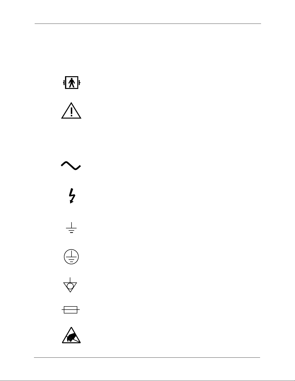
Symbols and Certification
If applicable, the following symbols appear on or near the serial number label or
other permanently affixed labels of this device. See the Specifications chapter for
more information.
1. This symbol indicates that the equipment applied part is Type BF,
defibrillation-proof per IEC 601.1.
2. This symbol indicates that consultation of the accompanyin g document s
prior to equipment operation is critical to the safe operation of the
device.
IPX1
3. This symbol indicates that the device meets the “drip proof”
classification requirements of IEC 601.1 under the applicable
conditions.
4. This symbol indicates that the device requires an alternating supply
current.
5. This symbol indicates that conductors carrying high voltage are nearby
and that these could be hazardous if contacted.
6. This symbol is located near functional ground locations on this device.
7. This symbol is located near protective ground locations on this device.
8. This symbol identifies the point of connection of a potential equalization
conductor.
9. This symbol indicates a fuse.
10. This symbol indicates that certain components within this equipment
are sensitive to electrostatic discharge.
xxii PRISMA
®
System Service Manual

Preface
Disclaimer
11. This symbol indicates that the equipment conforms to Council Directive
93/42/EEC, of 14 June, 1993 relating to Medical Devices. Also indicates
that the notified body which has approved the manufacturer’s quality
system is the British Standards Institution (BSI). The CE Mark affixed to
the PRISMA Control Unit covers only the PRISMA Control Unit.
Disposables specified for use with the PRISMA Control Unit have
separate CE Marks. See Warning number 7.
The manufacturer (and/or subsidiaries) accepts responsibility for the safety,
reliability, and performance of this equipment only if all operational procedures,
calibrations, and repairs are carried out by appropriately trai ned and qualified
people; if all equipment modifications are authorized in writing by the
manufacturer and carried out by appropriately trained and qualified people; if the
electrical installation of the relevant room complies with all applicable local
electrical codes and, if applicable, IEC requirement s; and if the equipment is used
in accordance with the published instructions for use (this document).
The manufacturer (and/or subsidiaries) will provide on request, at nominal cost, a
service manual which contains all necessary circuit diagrams, component parts
lists, calibration instructions, and service information to enable appropriately
trained and qualified technical personnel to repair those parts of this equipment
which the manufacturer considers to be repairable.
PRISMA
®
System Service Manual xxiii

Preface
Service Information
For technical assistance, contact your representative at the applicable address
below.
AUSTRALIA GAMBRO PTY Ltd.
AUSTRIA HOSPAL Medizintechnische Produkte
P.O. Box 6604 BHBC
Baulkham Hills
3, Hudson Avenue
Castle Hill
NEW SOUTH WALES 2154
Tel. 61 - 2 9 680 27 11
Fax 61 - 2 9 634 13 75
GmbH
Ricoweg 30 A
A-2351 Wr. NEUDORF
Tel. 43/2.23.664.666
Fax 43/2.23.664.666-55
BELGIUM HOSPAL S.A.
Groenveldstraat, 11
B - 3001 HEVERLEE
Tel. 32 / 16 31 10 20
Fax 32 / 16 31 10 39
BRAZIL GAMBRO do Brasil Ltda
Avenida Luiz Carlos Berrini 1297
Conjunto 92
BR-04571 SAO PAOLO
Tel. 55 - 11 55 06 90 12
Fax 55 - 11 55 06 47 04
CANADA HOSPAL GAMBRO Inc
9157, du Champ D´eau Street
St. Leonard
CA-QUEBEC H1P 3M3
Tel. 1 - 514 327 16 35
Fax 1 - 514 327 08 22
FRANCE HOSPAL SA
61 av. Tony Garnier
F - 69007 Lyon
Tel. 33 / (0) 4 37 28 11 11
Fax 33 / (0) 4 37 28 11 44
GERMANY Gambro HOSPAL GmbH
Lochhamer Str. 15
D - 82152 Planegg-Martinsried
Tel. 49 / (0) 89. 89933-0
Fax 49 / (0) 89. 89933-2999
xxiv PRISMA® System Service Manual

ITALY HOSPAL SpA
Via Ferrarese, 219/9
I - 40 128 Bologna
Tel. 39 / 051 63 82 411
Fax 39 / 051 32 74 77
NETHERLANDS GAMBRO HOSPAL BV
Franse Akker 1
NL - 4824 AL BREDA
Tel. +31 / (0) 76 530 3600
Fax +31 / (0) 76 541 1968
Preface
MEXICO
SP AIN HOSP AL SA
SWITZERLAND HOSP AL GAMBRO SCHWEIZ AG
UNITED KINGDOM HOSPAL GAMBRO Ltd
REST of EUROPE ,
AFRICA & MIDDLE EAST
GAMBRO de MEXICO S.A. de CV
Vasco de Quiroga 1900, Piso 3
MX-Santa Fe
MEXICO D. F. 01210
Tel. 52 - 52 92 31 00
Fax 52 - 52 92 31 13
Nápoles, 249 - 1°
E - 08013 Barcelona
Tel. 34 / 93 457 00 74
Fax 34 / 93 457 76 72
Sägereistrasse 24
CH - 8152 GLATTBRUGG
Tel. 41/ 1 828 82 82
Fax 41/ 1 828 82 83
Unit 1, Ermine Business Park
Huntingdon
GB-CAMBRIDGESHIRE PE18 6YA
Tel. 44 / 1480 444 000
Fax 44 / 1480 434 084
HOSPAL GAMBRO EXPORT
Magistratsvagen 10
P.O. Box 10101
S - 220 10 Lund
To order Parts :
Fax 46/46 169 610
Middle East: Tel. 46/46 169 134
Africa: Tel. 46/46 169 270
Russia: Tel. 46/46 169 171
East Europe: Tel. 46/45 169 171
PRISMA® System Service Manual xxv

Preface
Disposal of Lithium Energy Cell
The PRISMA Control Unit contains a lithium energy cell. The cell is embedded in
a semiconductor on the monitor circuit card assembly. When replacing this
component, follow local regulations for proper disposal.
Disposal of Packaging Material
The PRISMA Control Unit shipping carton, foam packing, and other packaging
material should be disposed of according to local regulations.
Warranty
Since GAMBRO DASCO has no knowledge or control of how non-GAMBRO
DASCO service work is conducted or what effect such work will have on a
machine’s operation and performance, GAMBRO DASCO will in no way be
responsible or liable for any damages resulting from the operation or performance
of any device, or any injury caused thereby, after repairs have been attempted by
anyone other than a factory representative of GAMBRO DASCO.
Under no circumstances will GAMBRO DASCO be liable for indirect or
consequential damages of any kind, its liability being hereby limited solely to
repair or replacement.
This warranty is in lieu of any other expressed or implied warranties, including an y
implied warranty of salability or fitness for use and of any other obligation on the
part of GAMBRO DASCO.
xxvi PRISMA
®
System Service Manual

Chapter 1: Introduction
Chapter 1: Introduction
Introduction
Blood Access
PRISMA Control Unit Functions
This service manual is for service technicians who will maintain and repair the
PRISMA
and understand the content s of this manual before attemp ting to repair or maintain
the machine. Only trained and qualified service technicians should perform the
procedures described in this manual.
The PRISMA System provides continuous fluid management, renal replacement
therapies, and therapeutic plasma exchange (as an option). The system is
intended for patients who have acute rena l failure and/or fluid overload, or p atients
with diseases where removal of plasma components is indicated.
All PRISMA therapies use venous blood access and return. A dual-lumen venous
catheter is the recommended blood access device; however, two single-lumen
venous catheters can also be used.
®
Control Unit. It is important that the service technician thoroughly read
The PRISMA Control Unit performs the following functions:
• Loads and primes the PRISMA Set automatically.
• Pumps blood through the blood flowpath of the set.
• Delivers anticoagulant solution into the blood flowpath.
• Controls fluid removal/plasma loss from the patient.
• Pumps sterile replacement solution/fluid and/or sterile dialysate. Pumps
• Monitors the system and alerts the operator to abnormal situations through
Therapy Overview
The PRISMA Control Unit pumps venous blood from the patient, through the filter
in a disposable PRISMA Set, and back to the patient’s venous circulation. As the
blood passes through the filter, fluid removal/plasma loss and/or solute clearance
can take place.
PRISMA
®
System Service Manual 1-1
effluent.
alarms.

Chapter 1: Introduction
PRISMA Therapy Options
The PRISMA System provides continuous fluid management, four different
continuous renal replacement therapies (CRRT), as well as therapeutic plasma
exchange (TPE) therapy. During the Setup procedure, the operator selects the
therapy desired.
• SCUF (Slow Continuous Ultrafiltration)
Provides patient fluid removal by ultrafiltration.
• CVVH (Continuous Veno-venous Hemofiltration)
Provides solute removal by convection. Can provide patient fluid removal, if
desired.
• CVVHD (Continuous Veno-venous Hemodialysis)
Provides solute clearance by diffusion. Can provide patient fluid removal, if
desired.
• CVVHDF (Continuous Veno-venous Hemodiafiltration)
Provides solute removal by both convection and diffusion. Can provide patient
fluid removal, if desired.
• TPE (Therapeutic Plasma Exchange; optional)
Provides plasma exchange by membrane filtration.
Mechanisms of Therapy
The mechanisms of ultrafiltration, hemofiltration, hemodialysis, and therapeutic
plasma exchange are used in providing the PRISMA therapy options.
Ultrafiltration
In ultrafiltration, plasma water with solutes is pulled from the patient’s blood
across the semipermeable membrane in the filter. The effluent pump
automatically controls the ultrafiltration rate.
Hemofiltration
In hemofiltration, plasma water with solutes is pulled from the patient’s blood
across the semipermeable membrane by means of ultrafiltration. A replacement
solution is simultaneously infused into the blood flowpath.
The replacement solution adds back some or all of the water removed, as well as
the wanted solutes. Unwanted solutes are not replaced, thus their concentration
decreases in the patient’s blood. Solute removal is achieved by convection
(solvent drag across the membrane).
Hemodialysis
In hemodialysis, unwanted solutes pass from the patient’s blood across the
semipermeable membrane and into dialysate flowing at counter flow through the
fluid compartment of the filter.
1-2 PRISMA
®
System Service Manual
 Loading...