

Hosola Bright Operation Manual
Hosola New Energy Co., Ltd.
Add: NO.328 Xinghu Road,Suzhou Industrial Park,China,215123
Tel:+86 512 6281 5763
Fax:+86 512 6281 5763-1888
E-mail:info@hosola.com
All rights reserved by Hosola

Copyright Declaration
The copyright of this manual belongs to Hosola New Energy Co., Ltd. Any corporation or
individual should not plagiarize, partially copy or fully copy it (including software, etc.). And
no reproduced or distributed of it in any form or by any means. All rights reserved.
Hosola reserves the right of final interpretation. This information is subject to changes
without notice.

1NOTES ON THIS MANUAL………………………………………………………………………5
1.1SCOPE OF VALIDITY…………………………………………………………………………5
1.2TARGET GROUP………………………………………………………………………………5
1.3 SYMBOLS USED………………………………………………………………………………5
2SAFETY……………………………………………………………………………………………5
2.1APPROPRIATE USAGE………………………………………………………………………5
2.2 IMPORTANT SAFETY INSTRUCTIONS……………………………………………………6
2.3EXPLANATION OF SYMBOLS ………………………………………………………………7
3 INTRODUCTION…………………………………………………………………………………8
3.1 BASIC FEATURES……………………………………………………………………………8
3.2 ELECTRICAL BLOCK DIAGRAM……………………………………………………………9
3.3 DIMENSION AND WEIGHT…………………………………………………………………10
4 SPECIFICATIONS………………………………………………………………………………11
4 .1 SPECIFICATIONS
(4200TL/ 5000TL)
…………………………………………………………11
5 FUNCTION………………………………………………………………………………………13
6 INSTALLATION…………………………………………………………………………………15
6.1 INSTALLATION………………………………………………………………………………15
6.2 PREPARATION………………………………………………………………………………17
6.3 INSTALLATION STEPS………………………………………………………………………17
6.4 CONNECTIONS OF THE PV POWER SYSTE……………………………………………20
6.5 RUN THE INVERTER………………………………………………………………………24
7 OPERATION METHOD………………………………………………………………………25
7.1 CONTROL PANEL……………………………………………………………………………25
Contents
7.2 LCD FUNCTION………………………………………………………………………………26
7.3 LCD INFORMATION…………………………………………………………………………28
8. COMMUNICATION AND MONITORING……………………………………………………30
8.1 COMMUNICATION INTERFACE……………………………………………………………30
8.2 COMMUNICATION…………………………………………………………………………30
9 TROUBLESHOOTING…………………………………………………………………………30
10 DECOMMISSIONING…………………………………………………………………………34
10.1DISMANTLING THE INVERTER……………………………………………………………34
10.2 PACKAGING…………………………………………………………………………………34
10.3 STORAGE……………………………………………………………………………………34
10.4DISPOSAL…………………………………………………………………………34
1 Notes on this Manual
1.1 Scope of Validity
This installation guide de Cscribes the assembly, installation, commissioning, mainte-
nance and failure search of the following Hosola inverters:
Hosola Bright Series:4200TL 5000TL
Store this manual where it will be accessible at all times.
1.2 Target Group
This manual is for qualified personnel. The tasks described in this manual may only be
performed by qualified personnel.
1.3 Symbols Used
The following types of safety instructions and general information appear in this docu-
ment as described below:
2 Safety
2.1 Appropriate Usage
The Hosola Series is a PV inverter which converts the DC current of a PV generator
Danger:
Danger indicates a hazardous situation which, if not avoided, will result in death or
serious injury.
Warning:
Warning indicates a hazardous situation which, if not avoided, could result in
death or serious injury.
Caution:
Caution indicates a hazardous situation which, if not avoided, could result in minor
or moderate injury.
Note:
Note provides tips that are valuable for the optimal operation of your product.
5
into AC current and feeds it into the public grid.
Principle of a PV plant
Figure 1 PV Grid-tied System
2.2 Important Safety Instructions
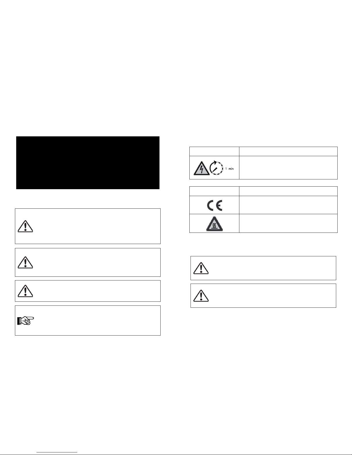
2.3 Explanation of Symbols
This section gives an explanation of all the symbols shown on the inverter and on the
type label.
2.3.1 Symbols on the Inverter
2.3.2 Symbols on the Type Label
2.3.1 Important Safety Instructions
When using the product, please do remember the below information to avoid the fire,
lightning or other personal injury:
1. Before using the Hosola inverter, read all instructions and cautionary markings on the
Hosola inverter, and all appropriate sections of this guide.
2. Use only attachments recommended or sold by Hosola. Doing otherwise may result in
a risk of fire, electric shock, or injury to persons.
Warning:
Ensure input DC voltage ≤625V. Over voltage may cause
permanent damage to inverter or other losses, which will not be included
in warranty! This chapter contains important safety and operating
instructions. Read and keep this Operation Guide for future reference.
Warning:
Authorized service personnel must disconnect both AC and DC
power from the Hosola inverter before attempting any maintenance or cleaning or
working on any circuits connected to the Hosola inverter.
Danger:
Danger to life due to high voltages in the inverter!
• All work on the inverter may be carried out by qualified personnel only.
• The appliance is not to be used by children or persons with reduced physical,
sensory or mental capabilities, or lack of experience and knowledge, unless they
have been given supervision or instruction.
• Children should be supervised to ensure that they do not play with the appliance.
Caution:
Danger of burn injuries due to hot enclosure parts!
During operation, the upper lid of the enclosure and the enclosure body may
become hot.
• Only touch the lower enclosure lid during operation.
Caution:
Possible damage to health as a result of the effects of radiation!
• Do not stay closer than 20 cm to the inverter for any length of time.
Note:
Grounding the PV generator
Comply with the local requirements for grounding the PV modules and the PV
generator. Hosola recommends connecting the generator frame and other
electrically conductive surfaces in a manner which ensures continuous conduction
and ground these in order to have optimal protection of the system and personnel.
Symbol Explanation
Danger to life due to high voltages in the inverter!
There is residual voltage in the inverter. The inverter requires 5
minutes to discharge.
Wait 5 minutes before you open the upper lid or the DC lid.
Symbol Explanation
CE mark.
The inverter complies with the requirements of the applicable
CE guidelines.
Beware of hot surface.
The inverter can become hot during operation. Avoid contact
during operation.
6 7
3. To avoid a risk of fire and electric shock, make sure that existing wiring is in good
condition and that wire is not undersized. Do not operate the Hosola inverter with
damaged or substandard wiring.
4. Do not disassemble the Hosola inverter. It contains no user-serviceable parts. See
Warranty for instructions on obtaining service. Attempting to service the Hosola inverter
yourself may result in a risk of electrical shock or fire and will void your warranty.
5. To reduce the risk of electrical shock, authorized service personnel must disconnect both
AC and DC power from the Hosola inverter before attempting any maintenance or
cleaning or working on any circuits connected to the Hosola inverter. Turning off controls
will not reduce this risk.
6. Keep away from flammable, explosive materials to avoid fire disaster.
7. The installation place should be away from humid or corrosive substance.
8. To avoid electric shock accident, please do not disassemble the inverter because inside
of inverter there are high-voltage capacitances installed. Fatal High-voltage will remain in
the inverter after its disconnection with grid after 5-10 minutes.
9. To reduce the chance of short-circuits, authorized service personnel must use insulated
tools when installing or working with this equipment.
3 Introduction
3.1 Basic Features
Congratulations on your purchase of a Hosola smart series inverter. The Hosola smart
inverter is one of the finest inverter on the market today, incorporating state-of-the-art
technology, high reliability, and convenient control features.
● Advanced MCU control technology;
● Utilize the latest high-efficiency power component from IR Company;
● Optimal MPPT technology;
● Advanced Anti-islanding solutions;
● IP65 protection level;
● Efficiency up to 97.1%;
● THD<3%;
● Safe & Reliable: transformerless design with software and hardware protection;
● Friendly HMI.
☆ LED status indications;
☆ LCD display technical data, Human-Machine interaction through press key;
☆ RS485/WIFI communication interface;
☆ PC remote control.
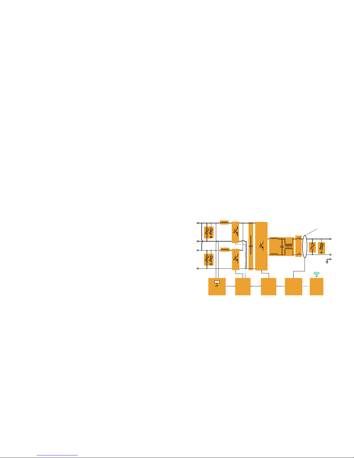
3.2 Electrical block diagram
3.2.1 Electrical block diagram, please see figure 2.
(4200TL /5000TL)
Figure 2
electrical block diagram
8 9
(DC/AC)
(DC/DC)
(CAP)
PV2+
PV2-
(DC/DC)
PV1+
PV1-
AC Leakage
Current
Detection
Ground Fault
Monitoring
DSP
Controller A
DSP
Controller B
Wi-fi
(Line Filter)
(Grid Parallel
Relay)
L
N
PE
GFCI
Model
Weight
Hosola Bright 4200TL
18.9Kg
Hosola Bright 5000TL
18.9Kg
Table 1 Weight
4 Specifications
4 .1Specifications
(
4200TL/5000TL
)
4.2.1 DC Input
10 11
3.3.2 Terminals of PV inverter
Figure 4 Terminal of PV inverters(4200TL/5000TL)
3.3 Dimension and Weight
3.3.1 Dimension
Figure 6 4200TL/5000TL
3.3.2 Weight
Model
4300Wp 5200Wp
625Vdc
300-500
Vdc
200 - 625 Vdc
300-500
Vdc
Max.DC power for each
MPPT [W]
Max. DC Voltage
MPPT voltage range [V]
Max. DC Current [A]
Numbers of MPPT
1
2
1
2
14.5 17.5
Strings per MPPT
Turn off DC Voltage [V]
Operating Voltage
Range [V]
Hosola Bright 4200TL Hosola Bright 5000TL
4300Wp 5200Wp
Max. DC Input Power
30 Vdc
 Loading...