

Hosola 1000TL, 1600TL, 2200TL, 2500TL, 3000TL Operation Manual

Hosola Smart Series
Grid-tied Inverter
Operation Guide
Hosola New Energy Co., Ltd.
Hosola-SM-V1-EN
Hosola New Energy Co., Ltd.
Add: NO.328 Xinghu Road,Suzhou Industrial Park,China,215123
Tel:+86 512 6281 5763
Fax:+86 512 6281 5763-1888
E-mail:info@hosola.com
All rights reserved by Hosola

Copyright Declaration
The copyright of this manual belongs to Hosola New Energy Co., Ltd. Any corporation or
individual should not plagiarize, partially copy or fully copy it (including software, etc.). And
no reproduced or distributed of it in any form or by any means. All rights reserved.
Hosola reserves the right of final interpretation. This information is subject to changes
without notice.

1 NOTES ON THIS MANUAL.................................................................................................5
1.1 SCOPE OF VALIDITY.......................................................................................................5
1.2 TARGET GROUP..............................................................................................................5
1.3 SYMBOLS USED.............................................................................................................5
2 SAFETY...............................................................................................................................5
2.1 APPROPRIATE USAGE...................................................................................................5
2.2 IMPORTANT SAFETY INSTRUCTIONS..........................................................................6
2.3 EXPLANATION OF SYMBOLS........................................................................................7
3 INTRODUCTION.................................................................................................................8
3.1 BASIC FEATURES...........................................................................................................8
3.2 ELECTRICAL BLOCK DIAGRAM.....................................................................................9
3.3 DIMENSION AND WEIGHT............................................................................................10
4 SPECIFICATIONS.............................................................................................................11
4.1 SPECIFICATIONS (1000TL/ 1600TL / 2200TL/ 2500TL / 3000TL)................................11
5 FUNCTION........................................................................................................................15
6 INSTALLATION..................................................................................................................16
6.1 INSTALLATION...............................................................................................................16
6.2 PREPARATION..............................................................................................................17
6.3 INSTALLATION STEPS..................................................................................................18
6.4 CONNECTIONS OF THE PV POWER SYSTEM...........................................................19
6.5 RUN THE INVERTER.....................................................................................................24
7 OPERATION METHOD.....................................................................................................25
7.1 CONTROL PANEL..........................................................................................................25
Contents

7.2 LCD FUNCTION.............................................................................................................26
7.3 LCD INFORMATION.......................................................................................................28
8. COMMUNICATION AND MONITORING..........................................................................30
8.1 COMMUNICATION INTERFACE....................................................................................30
8.2 COMMUNICATION.........................................................................................................31
9 TROUBLESHOOTING.......................................................................................................34
10 DECOMMISSIONING......................................................................................................37
10.1DISMANTLING THE INVERTER...................................................................................37
10.2 PACKAGING.................................................................................................................37
10.3 STORAGE....................................................................................................................37
10.4 DISPOSAL....................................................................................................................37
11 RECOMMENDED OPTIMAL CONFIGURATION FOR HOSOLA INVERTERS..............39
12 PALLET PACKING...........................................................................................................40
13 PHOENIX DC COUPLERS CONNECTION GUIDE(OPTIONAL)....................................40
14 HOSOLA SOLARMAN QUICK_SETUP MANUAL(WIFI OPTIONAL)..............................41
1 Notes on this Manual
1.1 Scope of Validity
This installation guide describes the assembly, installation, commissioning, maintenance
and failure search of the following Hosola inverters:
Hosola Smart Series: 1000TL 1600TL 2200TL 2500TL 3000TL
Store this manual where it will be accessible at all times.
1.2 Target Group
This manual is for qualified personnel. The tasks described in this manual may only be
performed by qualified personnel.
1.3 Symbols Used
The following types of safety instructions and general information appear in this document
as described below:
2 Safety
2.1 Appropriate Usage
The Hosola Series is a PV inverter which converts the DC current of a PV generator into AC
current and feeds it into the public grid.
Danger:
Danger indicates a hazardous situation which, if not avoided, will result in death or
serious injury.
Warning:
Warning indicates a hazardous situation which, if not avoided, could result in
death or serious injury.
Caution:
Caution indicates a hazardous situation which, if not avoided, could result in minor
or moderate injury.
Note:
Note provides tips that are valuable for the optimal operation of your product.
5
Principle of a PV plant
Figure 1 PV Grid-tied System
2.2 Important Safety Instructions
2.3 Explanation of Symbols
This section gives an explanation of all the symbols shown on the inverter and on the
type label.
2.3.1 Symbols on the Inverter
2.3.2 Symbols on the Type Label
2.3.3 Important Safety Instructions
When using the product, please do remember the below information to avoid the fire,
lightning or other personal injury:
1. Before using the Hosola inverter, read all instructions and cautionary markings on the
Hosola inverter, and all appropriate sections of this guide.
2. Use only attachments recommended or sold by Hosola. Doing otherwise may result in
a risk of fire, electric shock, or injury to persons.
Danger:
Danger to life due to high voltages in the inverter!
• All work on the inverter may be carried out by qualified personnel only.
• The appliance is not to be used by children or persons with reduced physical,
sensory or mental capabilities, or lack of experience and knowledge, unless they
have been given supervision or instruction.
• Children should be supervised to ensure that they do not play with the appliance.
Caution:
Danger of burn injuries due to hot enclosure parts!
During operation, the upper lid of the enclosure and the enclosure body may
become hot.
• Only touch the lower enclosure lid during operation.
Warning:
Ensure input DC voltage ≤550V. Over voltage may cause
permanent damage to inverter or other losses, which will not be included
in warranty! This chapter contains important safety and operating
instructions. Read and keep this Operation Guide for future reference.
Warning:
Authorized service personnel must disconnect both AC and DC
power from the Hosola inverter before attempting any maintenance or cleaning or
working on any circuits connected to the Hosola inverter.
Caution:
Possible damage to health as a result of the effects of radiation!
• Do not stay closer than 20 cm to the inverter for any length of time.
Note:
Grounding the PV generator
Comply with the local requirements for grounding the PV modules and the PV
generator. Hosola recommends connecting the generator frame and other
electrically conductive surfaces in a manner which ensures continuous conduction
and ground these in order to have optimal protection of the system and personnel.
Symbol Explanation
Danger to life due to high voltages in the inverter!
There is residual voltage in the inverter. The inverter requires 5
minutes to discharge.
Wait 5 minutes before you open the upper lid or the DC lid.
Symbol Explanation
CE mark.
The inverter complies with the requirements of the applicable
CE guidelines.
Beware of hot surface.
The inverter can become hot during operation. Avoid contact
during operation.
6 7
3. To avoid a risk of fire and electric shock, make sure that existing wiring is in good
condition and that wire is not undersized. Do not operate the Hosola inverter with
damaged or substandard wiring.
4. Do not disassemble the Hosola inverter. It contains no user-serviceable parts. See
Warranty for instructions on obtaining service. Attempting to service the Hosola inverter
yourself may result in a risk of electrical shock or fire and will void your warranty.
5. To reduce the risk of electrical shock, authorized service personnel must disconnect both
AC and DC power from the Hosola inverter before attempting any maintenance or
cleaning or working on any circuits connected to the Hosola inverter. Turning off controls
will not reduce this risk.
6. Keep away from flammable, explosive materials to avoid fire disaster.
7. The installation place should be away from humid or corrosive substance.
8. To avoid electric shock accident, please do not disassemble the inverter because inside
of inverter there are high-voltage capacitances installed. Fatal High-voltage will remain in
the inverter after its disconnection with grid after 5-10 minutes.
9. To reduce the chance of short-circuits, authorized service personnel must use insulated
tools when installing or working with this equipment.
3 Introduction
3.1 Basic Features
Congratulations on your purchase of a Hosola smart series inverter. The Hosola smart
inverter is one of the finest inverter on the market today, incorporating state-of-the-art
technology, high reliability, and convenient control features.
● Advanced MCU control technology;
● Utilize the latest high-efficiency power component from IR Company;
● Optimal MPPT technology;
● Advanced Anti-islanding solutions;
● IP65 protection level;
● Efficiency up to 97.1%;
● THD<3%;
● Safe & Reliable: transformerless design with software and hardware protection;
● Friendly HMI.
☆ LED status indications;
☆ LCD display technical data, Human-Machine interaction through press key;
☆ RS232/WIFI communication interface;
☆ PC remote control.
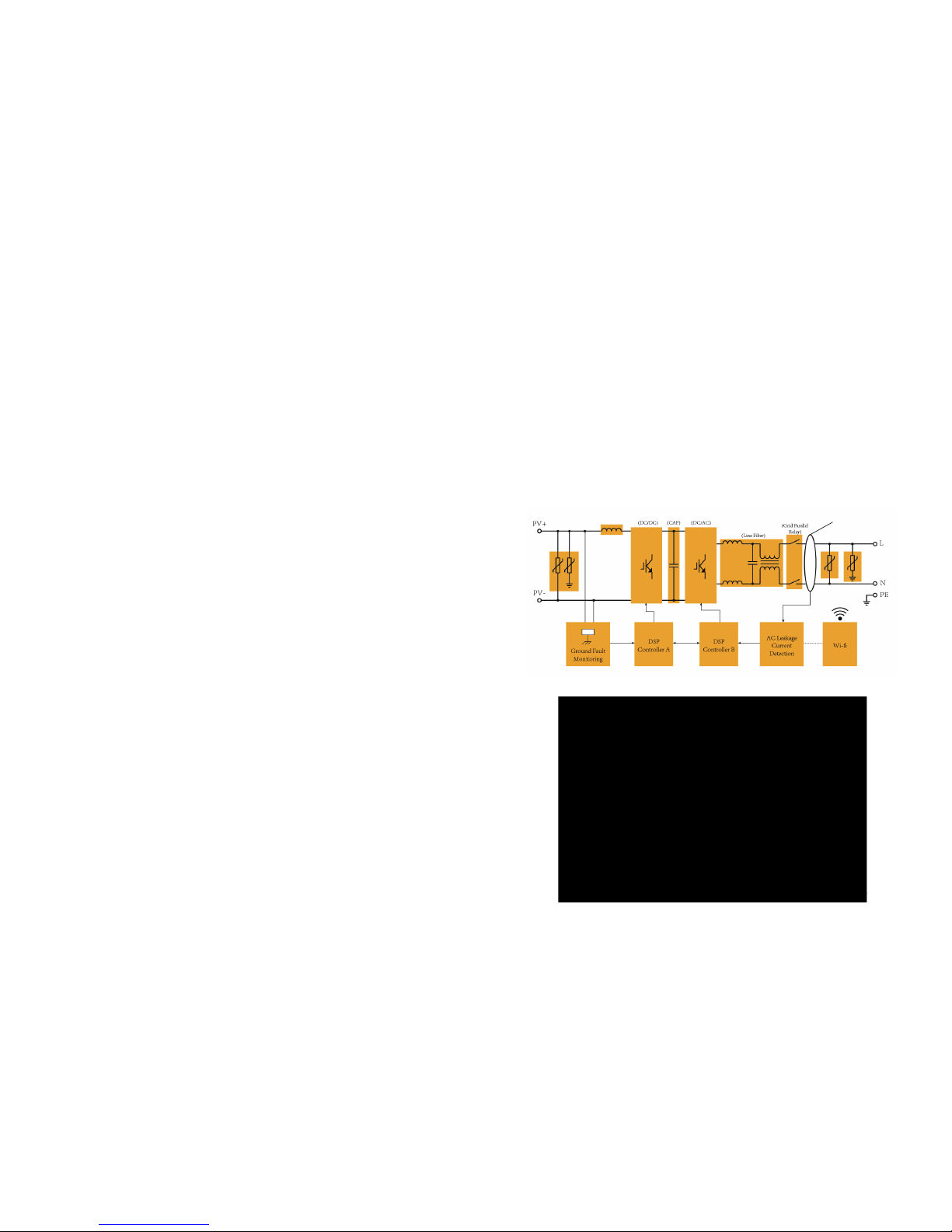
3.2 Electrical block diagram
3.2.1 Electrical block diagram, please see figure 2.
Figure 2
Electrical Block Diagram
3.3.2 Terminals of PV inverter
Figure 3
Terminal of PV inverters(1000TL/ 1600TL / 2200TL/ 2500TL / 3000TL)
8 9
GFCI

Model
Hosola Smart
1000TL
Hosola Smart
1600TL
Hosola Smart
2200TL
Hosola Smart
2500TL
Hosola Smart
3000TL
Weight 10Kg 10.2Kg 10.5Kg 13Kg 13Kg
Model
Hosola Smart
1000TL
Hosola Smart
1600TL
Hosola Smart
2200TL
Hosola Smart
2500TL
Hosola Smart
3000TL
1000 W 1600 W 2200 W 2500 W 3000 W
1000 W 1600 W 2200 W 2500 W 3000 W
5A 8A 11A 12 A 14 A
Model
Hosola Smart
1000TL
Hosola Smart
1600TL
Hosola Smart
2200TL
Hosola Smart
2500TL
Hosola Smart
3000TL
1100Wp 1750Wp 2350Wp
550 Vdc
100 - 550 Vdc
30 Vdc
2700Wp 3200Wp
130-500
Vdc
175-500
Vdc
180-500
Vdc
210-500
Vdc
240-500
Vdc
8.5A 10A 13A 13A 13A
1 1 1 1 1
1 1 1 1 1
Max.
DC Input Power
Max.
DC Voltage
MPPT
Voltage Range [V]
Operating
Voltage Range [V]
Turn off
DC Voltage [V]
Max.
DC Current [A]
No. of MPPT
Strings per MPPT
Grid Connection
Single phase
230 / 180 ~ 270
50 / 47 ~ 53
>0.99
<3%(Rated power)
0 W
<10 W
Rated
Output Power
Max.
Output Power
Rated AC
Voltage /Range [V]
Rated AC
Frequency /
Range [Hz]
Max.
Output Current
THD
Night
Consumption
Operation Power
Consumption
Power Factor
3.3 Dimension and Weight
3.3.1 Dimension
Figure 5
1000TL/ 1600TL / 2200TL/ 2500TL/ 3000TL
3.3.2 Weight
Table 1
Weight
4 Specifications
4 .1 Specifications (1000TL / 1600TL / 2200TL/ 2500TL/ 3000TL )
4.1.1 DC Input
4.1.2 AC Output
10 11
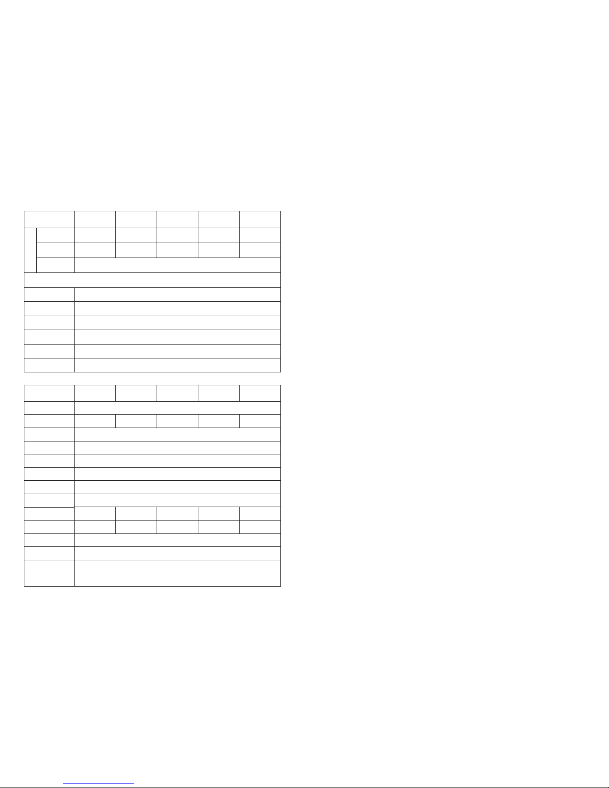
4.1.3 Efficiency, Safety and Protection
4.1.4 General Specification
5 Function
Operation Mode
【Stand-by Mode】
The stand-by mode means that the inverter is ready to but still not connect to the grid.
Under this mode, it will continue check if PV array has enough power to feedback into grid.
When the inverter passes dump load test after startup, it will change from stand-by mode to
checking mode.
【Checking Mode】
If inverter passed dump load test and no error/fault occurs, starts checking to deliver power.
【On-Grid Mode】
Under this mode, inverters convert PV array’s DC into AC and feedback into grid.
CAUTION:
The inverter decreases the output power is normal in the condition of thermal protection,
but if this phenomenon often occurred, you need to check the heatsink, or considering put
the inverter in the place where have better air flow. If output power decreases caused by
electrical, please ask for professional supports.
【MPPT Mode】
The default setting is MPPT mode, the operation mode will return to MPPT after DC&AC
restart. The MPPT voltage range of Hosola Smart series
1000TL/1600TL/2200TL/2500TL/3000TL is 130/175/180/210/230V~500V.
【Fault Mode】
If any fault/error occurred, inverter stopped delivering power until the fault/error is clear.
Some fault/error will auto recover, and some need manually restart.
【Setting Mode】
The user can get into the setting mode by press “Function” key for 6 seconds if DC is exist.
The detail information please refers to operation method in chapter 7.
Model
Hosola Smart
1000TL
Hosola Smart
1600TL
Hosola Smart
2200TL
Hosola Smart
2500TL
Hosola Smart
3000TL
10kg 10.2kg 10.5kg
283*363*128 mm
13kg 13kg
Wall-mounted
-20 °C ~ +60 °C
IP 65
Transformerless
Convection
< 35 dB < 35 dB < 35 dB < 35 dB < 35 dB
Convection Convection Convection Convection
Dimension
(W/H/D)
Weight
Installation
Operating
Temperature Range
Isolation Type
Cooling
Noise Level
RS232/Wifi(optional)
Communication
Interface
5 years
AS4777,G83,G59,EN61000-3-2,EN61000-6-1/2/3/4,IEC-62109-1,
IEC-62109-2,VDE0126-1-1,EN50438
Standard Warranty
Certificates
Protection Level
<2000 m
0% ~ 95%, no condensation
Altitude
Relative Humidity
12 13
Model
Hosola Smart
1000TL
Hosola Smart
1600TL
Hosola Smart
2200TL
Hosola Smart
2500TL
Hosola Smart
3000TL
96.5% 96.5% 96.5% 96.5% 96.5%
99.9%
Safety & Protection
97.0% 97.0% 97.1% 97.1% 97.1%
Max.
Efficiency
Euro
Efficiency
MPPT
Efficiency
Overvoltage
Protection
Efficiency
Mains Monitoring
Earth Fault
Current Monitoring
DC Injection
Monitoring
Earth Fault
Protection
Islanding Protection
Yes
Yes
Yes
Yes
Yes
Yes
6 Installation
6.1 Installation
Attention:
Checking environment where system is installed.
Check whether the installation site does not fall into none of the following conditions:
1. The ambient temperature is outside the range of tolerable ambient temperature
( -20°C to +60°C, -4°F to +140°F).
2. Higher than the altitude of about 2,000 m above sea level.
3. Prone to damage by sea water.
4. Close to corrosive gas or liquid (for example, locations where chemicals are
processed, feed lots or poultry).
5. Exposed to direct sunlight.
6. Prone to flooding or high levels of snow pack.
7. Minimal or no air flow and high humidity.
8. Condensations.
9. Exposure to steam, vapor, or water.
10. Exposure to direct cool air.
11. Near television antenna or antenna cable.
12. Ventilation is not enough to cool the inverter, that is to say, outdoors, the
inverter requires. At least 30 cm (see table 2) of clearance between the button
of the unit and the ground, indoors, it is recommended that the same
clearance between the button of the unit and the floor be used. Installing the
inverter in the place mentioned above may cause the malfunction of the
system caused by water or high temperature inside the inverter. Please let
usersknow that Hosola will not compensate the fault caused by the above
situation.
Note(for Hosola Smart series):
1. The PV modules should have an IEC61730 Class A rating or equivalent. The
resistance between PV positive or negative and ground must be more than 600kohm.
2. This product can cause a dc current in the external protective earthing conductor.
Where a residual current-operated protective (RCD) or monitoring (RCM) device is
used for protection in a case of direct or indirect contact, only an RCD or RCM of Type
B is allowed on the supply side of this product.
3. The installation place should be away from humid or corrosive substance.
4. The Hosola inverters can be used outdoor.
5. Users can check the firmware version via LCD function as shown below.
6. The Isc PV is can be referred as Max. DC current.
7. The AC output inrush current is 20A with duration time 2us.
8. The maximum output fault current of AC output is below 15mA RMS.
9. The maximum output over current protection can be referred as Max. output current.
14 15
Warning:
The open voltage of the PV array must be less than550V.
Over voltage may cause permanent damage to inverter .
Caution!
Installtion shall comply with local regulations and technical rules.
Installtion shall comply with the relevant instructions of EN62109-1/2.
Warning:
A warning that when the photovoltaic array is exposed to light, it supplies a DC.
voltage to the PCE.
Residual current protection:
Residual current detection and monitoring unit integrated inside,an external
residual current breaker is not required.
If an external RCD or residual current breaker is strctly required,you must use a
switch that triggers at a failure current of 100mA or higher.
 Loading...