

HOSOKAWA MICRON POWDER SYSTEMS
10 Chatham Road, Summit, NJ 07901 · Tel. (908) 273-6360 · Fax (908) 273-7432
Revision
Date
Description
Issue
October 23, 2018
Issue
Carefully read this manual
before operating or servicing this equipment
OPERATING & MAINTENANCE
MANUAL
Mikro Air Jet Sieve®
Document No.: M691477 – 181023.01
Record the MODEL and SERIAL NUMBER of your Air Jet Sieve and always refer to them when
ordering replacement parts or requesting service assistance.
Please refer to pages 46 through 56 for additional Service Information
OPERATING AND MAINTENANCE MANUAL
Mikro Air Jet Sieve®
IMPORTANT NOTICE:
(1) Before installing, operating or maintaining this instrument, carefully read this Manual and
follow the safety recommendations in Section 3.
(2) Reproduction of this manual in part or in whole is strictly prohibited without prior permission
from Hosokawa Micron Powder Systems.
(3) The contents of this manual are subject to change without notice.
(4) The contents of this manual have been carefully prepared. If you have any questions, find
errors or omissions, please contact Hosokawa Micron Powder Systems.
(5) Hosokawa Micron Powder Systems does not permit the improper use or handling of this
product by a third party. Only Hosokawa Micron Powder Systems service personnel are
authorized to repair or modify this product. Note that Hosokawa Micron Powder Systems
assumes no responsibility for damage or injury attributed to repairs, changes, etc. performed
by a third party.
(6) Hosokawa Micron Powder Systems assumes no responsibility for damages or injury
resulting from the attaching, using options or consumables other than Hosokawa Micron
Powder Systems genuine qualified parts.
(7) The software of this product is owned by Hosokawa Micron Powder Systems and copyright
protected. Copying the software and/or instruction manual in part or whole without
permission from Hosokawa Micron Powder Systems is prohibited.
(8) The MAJSx was designed for use with the Hosokawa Micron Test Sieve Screens. While other
manufactures screens can and do fit the instrument, Hosokawa Micron Powder Systems
cannot guarantee operational results and is not responsible should any damage occur.
(9) The warranty period of this machine is one (1) year from the date of shipment. Any
Dismantling, Tampering “Opening” or “Removal” of Fixed Components will VOID the
Warranty, unless specified herein.
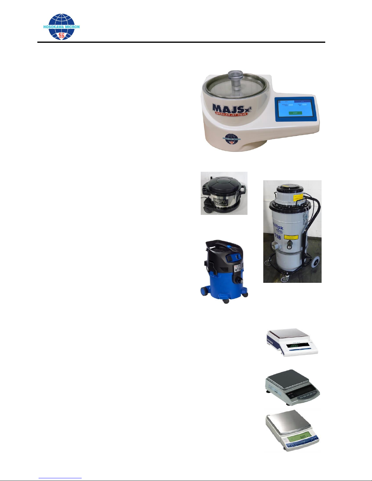
Introduction
The Mikro Air Jet Sieve® is a highly accurate and reliable particle size analyzer designed for determining
the particle size distribution of dry powder ranging from 20 μm to 4,750 μm.
Record your Air Jet Sieve MODEL and SERIAL NUMBER.
Refer to them when ordering replacement parts or requesting service assistance.
Page 2 of 56
OPERATING AND MAINTENANCE MANUAL
Mikro Air Jet Sieve®
CRITICAL INFORMATION:
This Instruction Manual describes the proper and safe operation of the Hosokawa Micron Product.
It is important that this Instruction Manual be read and fully understood before equipment
installation, operation, maintenance and/or inspection of this instrument. Especially, complete
understanding of the warning labels, as contained in this manual for safe operation of this
instrument.
Prediction of all possible operation hazards as defined in the manual is impossible however; the
dangers can be minimized by following the instructions described in this manual. Operate this
device with great care and make every endeavor to avoid any accident or damage to the device.
Page 3 of 56

OPERATING AND MAINTENANCE MANUAL
Mikro Air Jet Sieve®
Table of Contents
Section 1: Process Description .................................................................................................................... 5
Section 2: Principles of Operation .............................................................................................................. 6
Section 3: Safety ........................................................................................................................................... 8
Section 3-1: Precautions ......................................................................................................................... 8
Section 3-2: Electrical Shock ............................................................................................................... 10
Section 3-3: Personal Protective Equipment ...................................................................................... 10
Section 3-4: Material Safety Data Sheet (MSDS) .............................................................................. 10
Section 3-5: First Aid ........................................................................................................................... 10
Section 3-6: Administrator & Supervisor Operators Instructions .................................................. 10
Section 4: What is in the Box..................................................................................................................... 11
Section 4-1: Major Components ......................................................................................................... 11
Section 5: Unpacking and Installation ..................................................................................................... 12
Section 5: Unpacking and Installation (continued) ................................................................................. 13
Section 6: General Arrangement Drawing .............................................................................................. 14
Section 7: MAJSx2 Operation Component Layout ................................................................................. 15
Section 8: Preparing the MAJSx2 Air Jet Sieve ....................................................................................... 16
Section 8-1: Power/Communication Panel .................................................................................... 16
Section 8-2: Cable Connection ....................................................................................................... 16
Section 9: Basic Model Operating Procedure (Factory Default) ............................................................. 17
Section 9-1: Power-up the MAJSx2 ...................................................................................................... 17
Section 9-2: Set-Up for Basic Operation ............................................................................................ 18
Section 9-3: Basic Mode (Manual) Operating Procedure ................................................................. 20
Section 10: Advance Model Operating Procedure (Optional) ................................................................. 22
Section 10-1: Power-up the MAJSx2 in the Advance Operation Mode ............................................ 22
Section 10-2: SIEVE Page ..................................................................................................................... 24
Section 10-3: REPORT Page ................................................................................................................ 32
Section 10-4: SETTINGS Page ............................................................................................................. 35
Section 11: Optimizing Sieving Times ....................................................................................................... 44
Section 12: Maintenance ............................................................................................................................. 44
Section 12-1: Disassembly and Cleaning ............................................................................................. 44
Section 12-2: Cleaning of Test Sieve Screens ...................................................................................... 45
Section 12-3: Test Sieve Screen Selection Chart ................................................................................. 46
Section 12-4: Test Sieve Screen Statical Data Terminology Chart ................................................... 47
Section 12-5: Recommended Test Sieve Screen Recertification Schedule ...................................... 47
Section 12-6: Troubleshooting .............................................................................................................. 48
Section 12-7: Critical Instrument Verification ................................................................................... 49
12-7.1 Verification of Vacuum Gauge ............................................................................................. 49
12-7.2 Verification of Timer ............................................................................................................. 49
12-7.3 Calibration of Test Sieve Screens ......................................................................................... 49
Section 12-8: Recommended Operating Parameters ........................................................................ 50
12-8.1 Mikro Air Jet Sieve® (MAJSx2) ............................................................................................ 50
12-8.2 Vacuum Pressure ................................................................................................................... 50
12-8.3 Sample Weight and Sieving Time. ....................................................................................... 50
12-8.4 Sieving of Difficult Material ................................................................................................. 51
Section 12-9: Instructions for Connecting the Cyclone to the MASJx2 ........................................... 51
12-9.1 Adhere to the following Instruction steps: .......................................................................... 51
Section 12-10: Instructions for Cleaning the Vacuum ...................................................................... 52
Section 12-11: Recommended Vacuum Filter Replacement ............................................................ 52
Section 13: Aftermarket Services .............................................................................................................. 55
Section 13-1: Aftermarket Service Regional Parts Coordinators .................................................... 56
Page 4 of 56

OPERATING AND MAINTENANCE MANUAL
Mikro Air Jet Sieve®
Section 1: Process Description
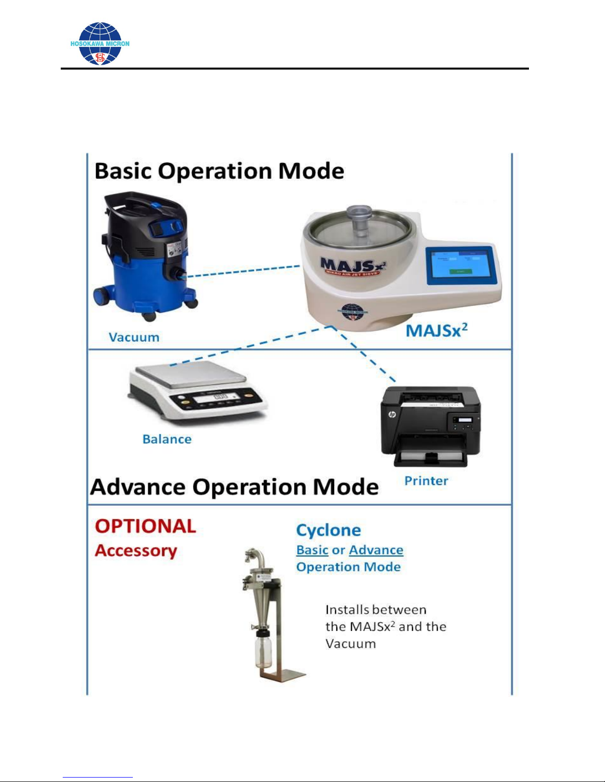
The Mikro Air Jet Sieve® – Model X2 (MAJSx2) is easy to operate and quickly determines particle size with
a short series of sieve test screens. The system utilizes the pneumatic sieving principle that enhances the
accuracy and reproducibility of particle size analysis. Use of this device has become a preferred method
for such tasks as quality assurance of incoming raw materials and confirmation of final product
specifications.
While under negative pressure sample particles are dispersed and de-agglomerated by means of a
positive airflow introduced upward through the rotating slit wand. Those particles small enough to pass
through a defined Test Sieve opening are carried in the airflow to the vacuum collector.
Precise particle size ranging from 20 to 4,750 μm can quickly be determined. This unique rotating wand
method also eliminates the need for tapping or brushing and increases reproducibility with controlled
measurements of pressure drop and duration. Overall the system is designed to operate cleaner, quieter
and requires less space than other types of similar analytical equipment.
The most important variables to insure a repeatable analysis using the Mikro Air Jet Sieve® are as follows:
The Sample Volume.
The Vacuum Pressure.
The Sieving Time.
The Test Sieve Screen Integrity.
Page 5 of 56
OPERATING AND MAINTENANCE MANUAL
Mikro Air Jet Sieve®
CRITICAL OPERATION INFORMATION:
The MAJSx2 was designed for use with the Hosokawa Micron Test Sieve Screens. While certain
manufactures screens can and do fit the instrument, Hosokawa Micron Powder Systems cannot
guarantee operational results and is not responsible should any damage occur.
Hosokawa Micron 200mm diameter Test Sieve Screens are supplied with a Blue Test Sieve Gasket and a
Black O-Ring. Remove and Discard the Blue Test Sieve Gasket. ONLY the Black O-Ring is to be used
on the Test Sieve Screen for proper vacuum seal.
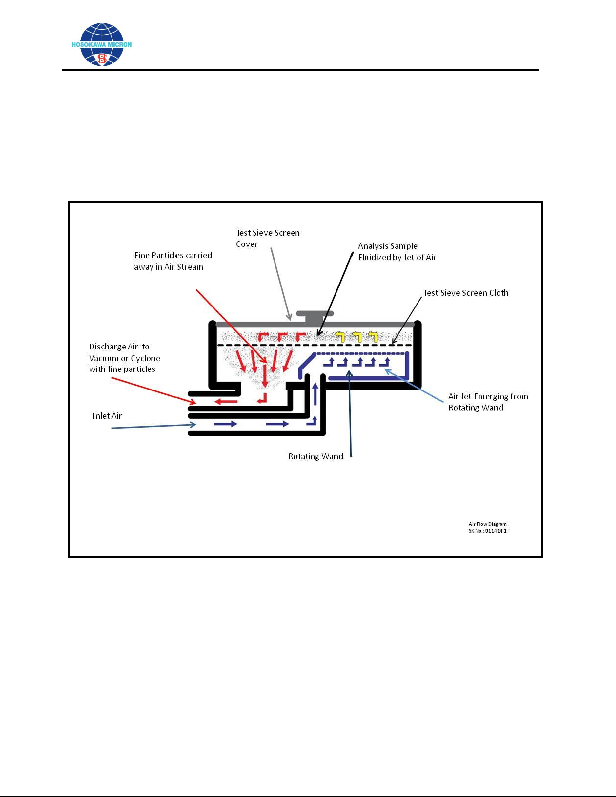
Section 2: Principles of Operation
The Mikro Air Jet Sieve® - Model x2 (MAJSx2) is a highly accurate and reliable particle size analyzer
designed to determine the particle size distribution of dry powders ranging from 20 to 4,750 micron. The
short sieving times at each sieve cut point are obtained by a reverse air current jetting out of a rotating air
wand beneath the Test Sieve Screens. This jetting air action disperses and distributes the analysis
material across the surface of the Test Sieve Screen. A Vacuum Fines Collector produces the required
airflow jetting action. The same airflow carries the fines fraction that passes through the Test Sieve
Screen, according to the principle of aerodynamic sifting. The fines fraction is then collected in either a
High Efficiency Cyclone or the Vacuum Fines Collector. A step-by-step description of this sieving action of
the Mikro Air Jet Sieve® as shown on Air Flow Diagram Sketch No.: 011414.1, on page 7 of 56 is as
follows:
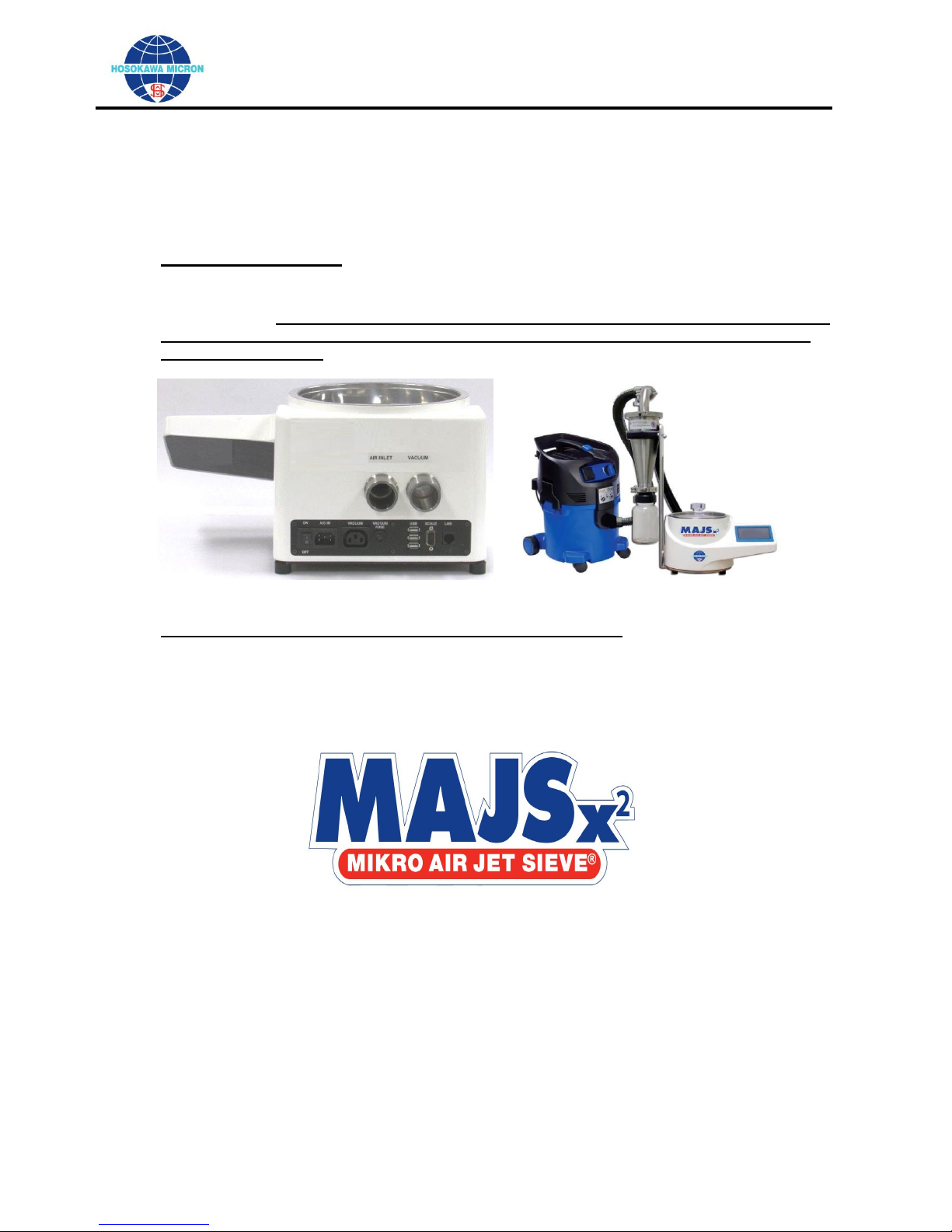
Air enters through the Air Inlet opening located on the back of the MAJSx2.
Air continues through the duct to the hollow rotation wand.
Air exits the special shaped slot in the top of the rotating wand with sufficient velocity to pass through
the Test Sieve Screen.
The wand is propelled by the electric motor, thereby sweeping the complete diameter of the sieving
area.
The jet of air distributes, de-blinds, (dislodges) and possibly de-agglomerates the powder analysis
sample residing on the top surface of the Test Sieve Screen.
Those particles fine enough to pass through the Test Sieve Screen are carried away in the air stream
and collected in the vacuum and/or cyclone.
Air and fine particles enter the primary discharge duct and exit the MAJSx2.
The vacuum pressure is set by the operator on the “Testing” screen (while in the advance mode) or
“Sieving” screen (while in the basic mode) and is automatically adjusted internally by a rotating valve
located between the “Air Inlet” and “Vacuum” air ducts.
The recommended vacuum pressure range, displayed on the “Testing” screen (while in the advance
mode) or “Sieving” screen (while in the basic mode) of the MAJSx2 during operation, should read
between 8 and 16 inches water column. Refer to page 49 for vacuum gauge verification procedures.
Utilizing the standard MAJSx2 arrangement, the fine dust particles and air exit the main unit and travel
through the vacuum hose to the vacuum collection canister.
If an optional cyclone is attached the dust-laden air is redirected to the cyclone and based upon the
efficiency of the cyclone the coarse particles are collected in the cyclone container and the ultra-fines
are carried in the air stream to the vacuum collection canister.
Page 6 of 56
OPERATING AND MAINTENANCE MANUAL
Mikro Air Jet Sieve®
Sketch No.: 011414.1
Page 7 of 56
OPERATING AND MAINTENANCE MANUAL
Mikro Air Jet Sieve®
SECTION 3 - 1:
Precautions
SECTION 3 - 2:
Electrical Shock
SECTION 3 - 3:
Personal Protective Equipment
SECTION 3 - 4:
MSDS (MATERIAL SAFETY DATA SHEET)
SECTION 3 - 5:
First Aid
SECTION 3 - 6:
Administrators and Supervisors of Operators’ Instructions
CAUTION:
Indicates that handling the machine improperly could result in severe personal injury, death or
serious property damage.
Locate the MAJSx2 in an area where the electrical components will not be exposed to water.
Locate the MAJSx2 in a place where it will not be adversely affected by high temperature, high
humidity or excessive dust. A safe operating temperature range is -10˚C ~ 60˚C (14˚F ~ 140˚F)
Relative humidity should not exceed 90% non-condensing.
Do not subject the MAJSx2 to strong shock or vibration. Doing so can and will result in failure of
the MAJSx2.
As specified by the Material Safety Data Sheet (MSDS) of the powder being analyzed, use
proper personal protection and/or a suitable respirator in accordance with plant policy, OSHA or
local regulations
Section 3: Safety
Section 3-1: Precautions
The precautions shown below are for safe operation of the MAJSx2.
In this instruction manual, in order to use the MAJSx2 safely, the following indications and symbols are
used to identify precautions.
Page 8 of 56
OPERATING AND MAINTENANCE MANUAL
Mikro Air Jet Sieve®
WARNING:
The instrument is to be properly grounded (earthed); not doing so may result in an electric
shock.
While the machine is energized and running, never open the Access Covers. Doing so may
cause injury.
Before performing maintenance, inspection, etc., turn OFF the power to the main body and
disconnect the power plug from the power receptacle. When touching parts in the machine,
wait for approximately 10 seconds or more after disconnecting the power plug. Not doing so
may cause an electric shock
Use ONLY the supplied power cable. If a power cable other than the one supplied is connected,
a fire, electric shock or serious failure may result.
Do not damage, place a heavy object on or forcedly pull the power cord. Doing so may result in
a fire and/or electric shock.
Do not use the machine in a place where combustible gas or ignitable products may be
present. Doing so may result in a fire.
Do not modify the machine.
This machine is not rated for use in a hazardous environment. Do not analyze flammable or
explosive materials.
When cleaning the pan area, refer to the maintenance service section of this manual for
additional information.
Use properly grounded power outlets for the MAJSx
2
, vacuum and all auxiliary equipment
attached to the sieving device
Page 9 of 56
OPERATING AND MAINTENANCE MANUAL
Mikro Air Jet Sieve®
Do not open the Access Covers on the bottom of the
instrument when energized.
Touching the electronic components inside may result in an
electric shock or damage to the electronics.
To protect the instrument from the effects of static electricity confirm the following:
Confirm that the Main Access Cover is attached with all four mounting threaded rubber
pads and that all of the pads are securely tightened and are in good condition.
Confirm that the touch screen panel bottom plate is attached and secured with all five (5)
screws.
Use properly grounded power outlets for the MAJSx2, vacuum and all auxiliary equipment
attached to the sieving device.
Section 3-2: Electrical Shock
Section 3-3: Personal Protective Equipment
When operating this instrument, wear dustproof goggles, dustproof masks, gloves, etc. as
required.
Section 3-4: Material Safety Data Sheet (MSDS)
When using this machine, carefully read and follow the MSDS pre-cautions for the specific powder
sample being analyzed.
Section 3-5: First Aid
In the event the analyzed powder comes in contact with the operators’ eyes, skin or is inhaled,
administer First Aid in accordance with the prior reviewed powder MSDS.
Section 3-6: Administrator & Supervisor Operators Instructions
Before installing, operating or maintaining this equipment all individuals involved in the installation,
operation and maintenance must carefully read and understand the contents of this manual and
follow the Safety Recommendations.
Page 10 of 56
OPERATING AND MAINTENANCE MANUAL
Mikro Air Jet Sieve®
MAJSx2
Mikro Air Jet Sieve® with threaded Wand
Tapping Hammer
Sieve Brush
Polycarbonate Test Sieve Screen Cover
Power Cord - IEC 60320 C-13 plug
Vacuum Cord Adapter with IEC 60320 C-14 and
appropriate receptacle.
Operation Manual
Vacuum (Model No.: 390 – 30 - 118)
Main Vacuum (Application Specific)
One (1) Primary collection bag (390 & 30 only)
One (1) minimum two (2) meter length of hose
with connection cuffs
For 110 volt vacuums - Power Cord Adapter
For 220 volt vacuums - one (1) C-14 fitting is
mounted on vacuum power cable.
Manufacturers Operation Manual
No.:390
No.:118
No.: 30
Compatible Electronic Balances
consisting of:
Balance Main Body
(DEFAULT Interface Settings)
Balance Pan
Balance Pan Support
Communication Cable
(Serial type in accordance with the
manufacturers specifications)
Power transformer
Manufacturers Operating / Instruction Manual
Mettler Toledo
model MS1602S
Rice Lake
model TP-3200
Shimadzu
model UX4200H
Section 4: What is in the Box
Section 4-1: Major Components
Page 11 of 56
OPERATING AND MAINTENANCE MANUAL
Mikro Air Jet Sieve®
The back of the MAJSx2 is to be positioned no less than a minimum of six
(6) inches from a wall or a solid obstruction to enable the operator easy
access to the “Power” switch and the Circuit protector.
Section 5: Unpacking and Installation
Unpack and remove the MAJSx2 from the shipping box. Confirm receipt of all required
components as detailed in the “What’s in the Box” section.
Place the accessories (sieve cover, tapping hammer, sieve brush, power cord and, depending
upon the model, the USB “Flash Drive” and CAT 5 cable) aside for the moment.
Locate the MAJSx2 on a level, firm horizontal laboratory bench/table capable of sustaining
vibration and positioned for easy operator access.
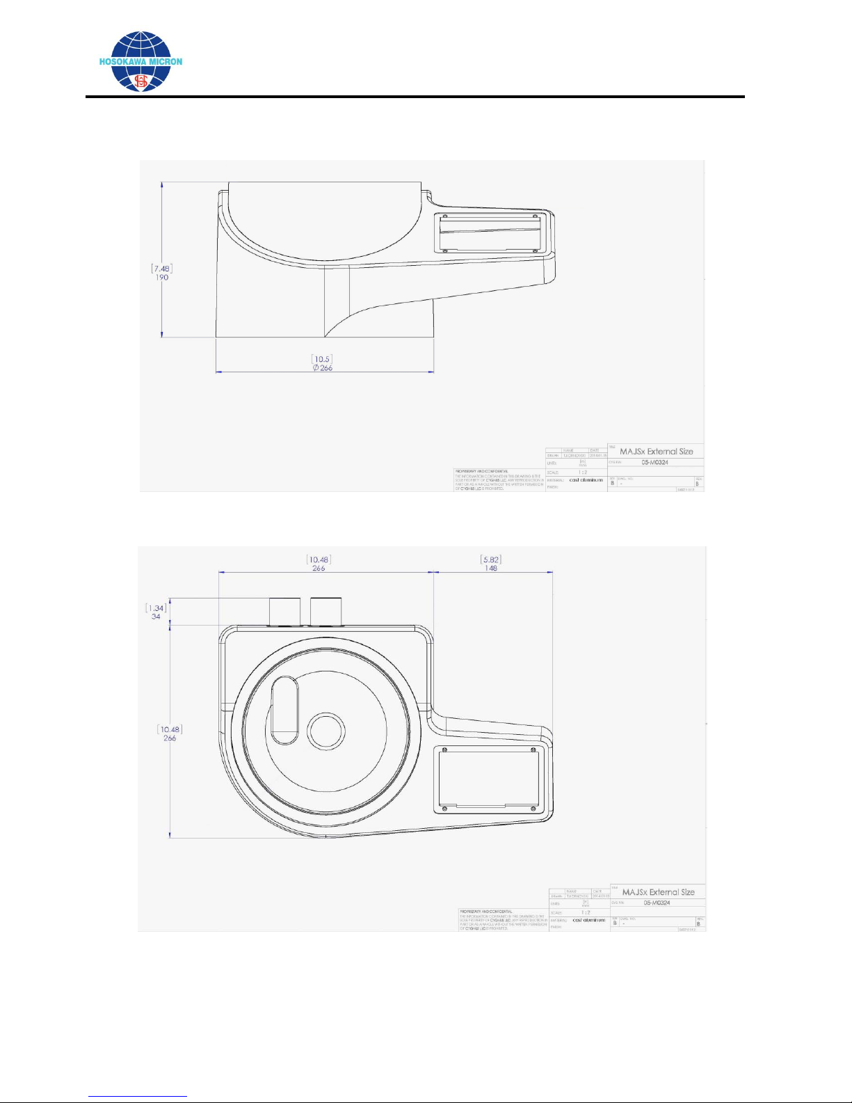
Refer to General Arrangement Drawing below for dimensions. The MAJSx2 weighs approximately
26 Lbs. (11.8 kg). All necessary CAUTIONS are to be used when lifting the instrument.
Prior to attaching the power cord to the MAJSx2, confirm that a 3-prong 90 to 240 volt, 50/60 hertz
grounded house outlet is within three (3) feet (36 inches) (1 meter) of the MAJSx2. The electrical
power outlet should have “Ground” (“Earth”) protection, and rated for a minimum of 15Amps@110
volt / 10Amps@230 volt, 60/50 Hertz.
Confirm that the power switch, located on the back of the MAJSx
the power cord into the receptacle located on the back (labeled “A/C IN”) of the MAJSx. Insert the
opposite end of the power cord into the house power receptacle.
MAJSx2 ADVANCED OPERATION: Insert the USB “Flash Drive” into one of the USB ports
located on the back (labeled “USB”) of the MAJSx2 for additional storage capacity. Note: The
MAJSx2 will recognizes each USB “Flash Drive” by clicking on the ICON located in the upper
left corner of the display.
Open/Unpack the vacuum and confirm receipt of all the required components (Vacuum Main Body,
One (1) Primary collection paper bag, and one (1) two (2) meter length (minimum) of hose with
connection cuffs, Power Cord, and Operation Manual). Additionally, confirm that the filters are
properly installed in accordance with the manufacturer’s instruction manual. Prior to closing the
vacuum, familiarization with the inside of the vacuum, especially the filter installation, is
recommended. Where ever possible, locate the vacuum, depending upon the vacuum physical
size, beneath or alongside of the lab bench/table. If mounted beneath the lab bench/table, to
eliminate the hose from being draped over the top of the bench/table, drill a 2.5 inch (63.5 mm)
diameter hole in the bench/table countertop. This size hole will provide ample clearance to pass
both the vacuum hose and vacuum power cord through the countertop making for a cleaner
installation.
After locating the vacuum under the bench/table or in another convenient location, plug the
vacuum power cord connector into the MAJSx2 female vacuum power receptacle, (rated for
15Amp@110 volt / 10A@230 volt) located on the back of the MAJSx2. NOTE: the vacuum
operating voltage MUST be the same as the voltage that is supplied to the MAJSx2. In order to
achieve reproducible analysis results using the MAJSx2, the vacuum MUST always be plugged
into the MAJSx2 power outlet IEC 60320 C-13 receptacle (or adapter), (rated for 15Amp@110 volt
/ 10Amp@230 volt) located on the back of the MAJSx2. The vacuum’s power switch MUST
always be in the “ON” position.
Using the supplied vacuum hose, connect the vacuum hose to the MAJSx2 vacuum port located on
the back of the MAJSx2, labeled “Vacuum Inlet”.
Page 12 of 56
2
, is in the “OFF” position. Insert
OPERATING AND MAINTENANCE MANUAL
Mikro Air Jet Sieve®
The MAJSx2 Advanced Model can be set-up to Print either directly to an
attached printer or to a Corporate Local Area Network (LAN) printer.
Installation / Powering the MAJSx2
Section 5: Unpacking and Installation (continued)
ELECTRONIC BALANCE FOR MAJSx2 ADVANCED OPERATION: Open/unpack the electronic
balance and confirm receipt of all the required components (balance main body, balance pan,
balance pan supporter, interface communication cable, power transformer, and instruction
manual). Depending upon the Electronic Balance Manufacturer, connect the supplied RS232
serial cable. The Electronic Balance MUST always be powered “ON” and connected to the
MAJSx
MAJSx2, the balance factory DEFAULT RS232 interface settings MUST be used.
Compatible balances are: Mettler Toledo model MS – Shimadzu model UX and Rice Lake
model TP
PRINTER FOR MAJSx2 ADVANCED PRINTING OPERATION: Confirm receipt of all required
components. The Printer components include the printer main body, toner cartridge; installation/
warranty guide, operations manual, and power cord, a USB Cable or a CAT 5 Network (LAN)
cable will be required for connection to the MAJSx2. When using a direct connected printer, locate
the printer, depending upon its physical size, as close as possible to the MAJSx2. After positioning
the printer, plug the printer power cord into an independent wall socket. Next make certain to
connect the printer USB cable to one of the USB ports located on the back of the MAJSx2. After
connecting the components, follow the manufacturer’s instructions to complete the installation.
When connecting the MAJSx
recommended to contact the local IT Department for installation clearances and
recommendations.
2
, prior to powering “ON” the MAJSx
2
ADVANCED model to a “CORPORATE LAN NETWORK” it is
2
. In order for the balance to communicate with the
Store the installation, operation and warranty manuals/guides in a safe location for future
reference.
In order to achieve reproducible analysis results using the MAJSx2, the vacuum MUST always be
plugged into the Vacuum Power outlet located on the back of the MAJSx2.
The vacuum power switch, located on the vacuum body MUST always be in the “ON” position.
The vacuum power outlet located on the back of the MAJSx2 is rated for a maximum of 15
Amp@230V, 50/60Hz, single phase.
When operating the MAJSx2 in Basic Mode, the instrument is NOT capable of communicating with
a balance and/or a printer.
When operating the MAJSx2 in the Advance mode, it is suggested that the Electronic Balance be
powered “ON” and connected to the MAJSx2, prior to powering “switching” ON” the MAJSx
2
.
When operating the MAJSx2 in the Advance mode, the MAJSx2 will display an ICON when a USB
“Flash Drive” and a Balance are connected and communication has been established.
The USB “Flash Drive” is used as an alternate storage location.
Connect the electrical power cord of the MAJSx2 and, if operating in the Advance mode, the
optional balance and printer to a suitable sized wall outlet, proper voltage 90 - 240V, 50/60Hz,
single phase.
Page 13 of 56
OPERATING AND MAINTENANCE MANUAL
Mikro Air Jet Sieve®
Section 6: General Arrangement Drawing
(Front View)
(Top View)
Page 14 of 56
OPERATING AND MAINTENANCE MANUAL
Mikro Air Jet Sieve®
Section 7: MAJSx2 Operation Component Layout
Page 15 of 56
OPERATING AND MAINTENANCE MANUAL
Mikro Air Jet Sieve®
Section 8: Preparing the MAJSx2 Air Jet Sieve
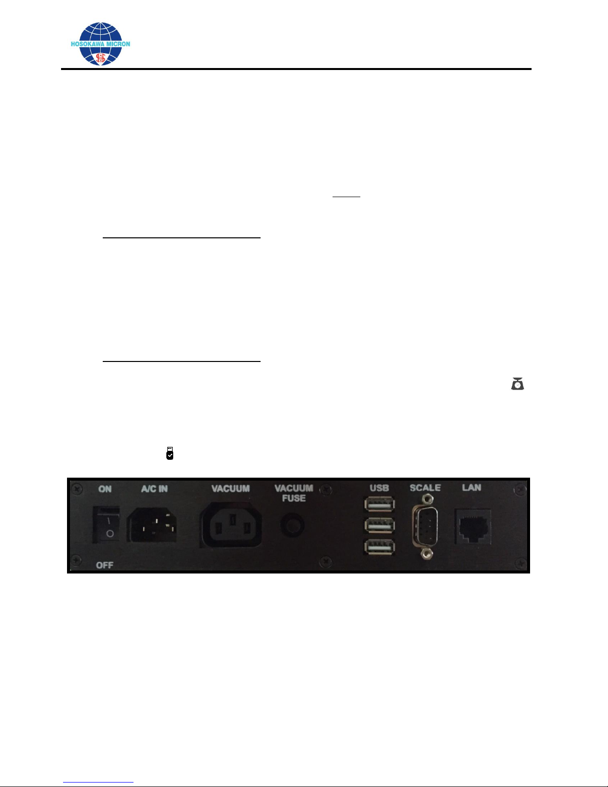
Section 8-1: Power/Communication Panel
(See Figure 1 - Left to Right)
Power “On/Off” switch
Main power “A/C IN” supply 90-240 volt, single phase, 50/60 hertz, current draw without the
vacuum attached is 0.5 amperes at 110 volt 60 Hertz, Single Phase.
Vacuum power “VACUUM” supply port, the vacuum MUST always be connected to the software
controlled “VACUUM” port of the MAJSx.
Vacuum receptacle fuse “VACUUM FUSE”
MAJSx Advanced Operation Only
o Three (3) USB ports permitting the connection of USB devices.
o One (1) RS232 DB9M serial port “SCALE” for the connection of a balance
o Local Area Network “LAN” port (CAT 5).
Section 8-2: Cable Connection
Insert the power cord in the “A/C IN” receptacle located on the back of the MAJSx
Insert/Connect the Vacuum power cord (or the vacuum power adapter cord) to the “VACUUM”
receptacle.
MAJSx Advanced Operation Only
o Connect a compatible “Balance” communication cable to the RS232 “SCALE” port
o Confirm that the Balance is recognized by the software and that the “Balance” ICON is
visibly dark black in the upper right corner of the screen. (see Figure 14).
o Connect the Network cable to the “LAN" port.
o Insert a USB “Flash Drive” into one of the USB ports on the back of the MAJSx2.
o Confirm that the USB “Flash Drive” is recognized by the software, and that the “USB”
ICON is visibly dark black in the upper left corner of the screen. (see Figure 4).
Figure 1
Page 16 of 56
OPERATING AND MAINTENANCE MANUAL
Mikro Air Jet Sieve®
Section 9: Basic Model Operating Procedure (Factory Default)
(For the Advanced Model (MAJSx
2
-a) proceed to page 23)
Section 9-1: Power-up the MAJSx
2
Basic Operation Mode
For the system to perform properly, connect the vacuum hose and the vacuum power cable to the
appropriate ports before energizing the MAJSx2-b.
Confirm that the vacuum is plugged into the MAJSx2 “VACUUM” receptacle (outlet) and that
the suction hose is connected to the “VACUUM” port (see Figure 1), both located on the
back of the MAJSx2-b.
Figure 2 Figure 2a
Confirm that the vacuum power switch is in the “ON” position.
Next, energize the MAJSx2-b, by pressing the “On/Off” rocker switch to the “ON” position located
on the back of the MAJSx2-b as displayed in Figures 1.
The touch screen of the MAJSx2-b will briefly display the Hosokawa Logo during the software
startup. (see Figure 3)
Figure 3
Page 17 of 56

OPERATING AND MAINTENANCE MANUAL
Mikro Air Jet Sieve®
After the software has completely opened, the “SIEVE” window will be displayed (see Figure 4).
Figure 4
Section 9-2: Set-Up for Basic Operation
The SIEVE window displays the START button along with the Sieving Parameters, including the
“Pressure” and “Time” default values. (see Figure 4).
To enter or change the “Pressure”, press the corresponding cell, whether blank or pre-populated.
By doing so the keyboard will be activated and displayed. After typing the desired information,
press the Next button to save the entered value and to open/display the “Time” keyboard. After
typing the desired information, press the Next button to close the keyboard and save the entered
or changed values. (see Figures 5a & 5b).
Figure 5a Figure 5b
Pressing the ADMININSTRATOR folder will open the window that will display the “IP Address”
and “MAC ADDRESS” numbers, “Language”, “Pressure Unit”, “Check USB Update” and “MAJSx
Advanced Mode” and “FACTORY SETTINGS” selection buttons. (see Figure 6)
Figure 6
The specific “IP Address” is displayed when the MAJSx2-b is connected to a network. (see
Figure 6)
The unique MAC Address assigned to this MAJSx2-b will be displayed after “MAC:” (See
Figure 6)
Page 18 of 56

OPERATING AND MAINTENANCE MANUAL
Mikro Air Jet Sieve®
The “Language” selection button is a pull-down menu enabling the Operator to select the
language that is to be displayed throughout the MAJSx2 software (English, Spanish, Hindi,
Dutch, French, German, Italian, Japanese, Portuguese, Russian, Korean and Chinese). (See
Figure 7)
“Pressure Unit” button is a pull-down menu enabling the operator to select the desired
pressure measurement unit (inch H2O, Pascal, mm Hg, inch Hg, or PSI).(see Figure 8)
“Check USB Update” compares the installed software version to that contained on an
installed flash drive where the operator can upload software updates/patches. (see Figure 9).
“MAJSx Advanced Mode” button, provided the operator has the individualized specific
“Password” to convert the MAJSx2-b, “Basic” mode of operation to the MAJSx2-a “Advanced”
mode of operation. Contact Hosokawa Micron Powder Systems for more Information (See
Figure 10).
Figure 7 Figure 8
Figure 9
FACTORY SETTINGS In order to access the Factory Settings while in Basic Mode a
Password is required Contact Hosokawa Micron Powder Systems (see Figure 10)
Figure 10
Page 19 of 56

OPERATING AND MAINTENANCE MANUAL
Mikro Air Jet Sieve®
The MAJSx2 is designed for use with the Hosokawa Micron Test Sieve Screens.
While other manufactures Test Sieve Screens can and do fit the MAJSx2, HMPS cannot
guarantee operational results, or be held responsible should any damage occur.
When using the HMPS 200mm Test Sieve Screens, both a Black O-ring and a Blue Test Sieve
Gasket are supplied.
The Black O-ring is recommended to insure a proper vacuum seal.
The Blue Test Sieve Gasket is NOT required and should be removed and discarded.
Section 9-3: Basic Mode (Manual) Operating Procedure
Connect the Vacuum to the MAJSx2-b.
Insert the Vacuum power cord into the “VACUUM” power outlet located on the back of the
MAJSx2-b. Once plugged into the MAJSx2-b, confirm that the vacuum power switch is set to the
“ON” position. (see Figure 1)
Connect the Vacuum hose cuff to the vacuum port on the back of the MAJSx2-b labeled
“VACUUM”. (see Figure 1)
Press the On/Off rocker switch, located on the back of the MAJSx2-b, to the “ON” position. (See
Figure 1)
The MAJSx2-b software will perform the start-up sequence. Upon completion the SIEVE page will
be displayed. (see Figure 4)
Figure 4
Prior to pressing the START button, set the “Pressure” and “Time” values to the desired level that
will be used during sieving operation.
To enter or change the “Pressure”, press the corresponding cell, whether blank or pre-populated.
By doing so the keyboard will open enabling the desired numeric value to be entered
(recommended vacuum pressure 8 to 16 inch water column.
After entering the desired value, press the NEXT button to save the entered value and to open the
“Time” keyboard. After typing the desired sieving Time, press the NEXT button to close the
keyboard and save the entered/changed values. (see Figure 5a & 5b)
To heighten repeatability, independently record the Test Sieve Screen Number (Mesh) or Micron
Size, Pressure and Time used for each analysis.
Page 20 of 56

OPERATING AND MAINTENANCE MANUAL
Mikro Air Jet Sieve®
Place the empty Test Sieve Screen on an independent balance and record the weight. Tare the
balance with the Test Sieve Screen remaining on the balance. Once tarred, place the sample
(suggested 10 to 100 grams) to be analyzed on the Test Sieve Screen and record the sample
weight.
Place the Test Sieve Screen with the sample on the MAJSx2-b and position the Test Sieve Cover
on the Test Sieve Screen.
With the Test Sieve Screen including the sample in place, using the previously entered sieving
parameters, press the START button to begin the analysis.
Once the START button is pressed, the MAJSx2-b sieving process will begin. The vacuum will
power and the slit wand will begin to rotate (clockwise) once the vacuum pressure reaches
approximately 7 inches of water column (or equivalent).
Should the desired Sieving Pressure not be reached, an error message will appear stating
“Pressure not Matched!” (see Figure 11)
Press the OK Button.
After pressing the OK button the software will return to the main “SIEVE” page. (see Figure 4)
Prior to restarting the process confirm that the Test Sieve Screen with the O-ring and the
Polycarbonate Test Sieve Screen Cover are properly seated in the MAJSx2-b housing, the vacuum
hose is properly connected, and the vacuum power switch is in the “ON” position.
In the event the condition continues, inspect the vacuum filters, as they may require cleaning.
After performing these checks press START. (see Figure 4).
Should the desired vacuum pressure continue not to be reached, refer to the guidelines in the
troubleshooting section of this manual.
Once the wand begins to rotate, the sieving time will begin to decrease. Both the Pressure and
the Time Left will be displayed on the screen, until the Time reaches 0 (see Figure 12)
Figure 11
Figure 12 Figure 13
Page 21 of 56

OPERATING AND MAINTENANCE MANUAL
Mikro Air Jet Sieve®
When using the MAJSx2 in the Basic Operation Mode, the MAJSx2-b is
NOT capable communicating with a balance or Printer.
If for any reason the process needs to be stopped, during the analysis (for example: to brush the
Test Sieve Cover free of statically charged sample) press the PAUSE button. (see Figure 12).
To re-start the analysis, press the RESUME button. If for whatever reason the analysis needs to
be aborted, press the ABORT button. (see Figure 13)
After the preset Time has reached 0, the wand will stop rotating, power to the vacuum will stop,
turning the vacuum off, and the MAJSx2-b screen will display the main SIEVE screen. (see Figure
4).
In order to determine the volume of the retained sample and complete the analysis, Tare the
independent balance, place the Test Sieve Screen with the retained sample on the balance.
Independently record the combined weight of the Retained Sample and the Test Sieve Screen.
Using the previously saved information (the Total Weight of the Test Sieve Screen and the
Sample) the operator can determine the weight of the retained sample.
In order to determine the percentage of the sample that has passed through the Test Sieve Screen
use the following formula.
Initial sample weight (A) minus the Retained sample weight (B) divided by the Initial sample weight
(A) x 100. (A – B ÷ A x 100)
Section 10: Advance Model Operating Procedure (Optional)
Section 10-1: Power-up the MAJSx2 in the Advance Operation Mode
For the system to perform properly, connect the vacuum hose and the vacuum power cable to the
appropriate ports before energizing the MAJSx2-a.
Confirm that the vacuum power cord is plugged into the MAJSx2 “VACUUM” receptacle
(outlet) and that the cuffed vacuum hose is connected to the “VACUUM” port (see Figure 2),
both located on the back of the MAJSx2-a.
Figure 2
Page 22 of 56

OPERATING AND MAINTENANCE MANUAL
Mikro Air Jet Sieve®
Confirm that the vacuum power switch is in the “ON” position.
Confirm that a compatible balance is connected to the MAJSx2-a by means of the RS232 serial
cable connection port located on the back of the MAJSx2-a (see Figure 1).
Confirm that the software recognized the compatible Balance. The “Balance” ICON in the
upper right corner will become dark black. (see Figure 14 ). In addition clicking on the ICON will
display the name of the connected balance.
Connect the Network cable to the “LAN" port (see Figure 1)
Insert the USB “Flash Drive” into one of the USB ports of the MAJSx2-a.
Confirm that the USB “Flash Drive” is recognized by the software. The “USB” ICON will become
dark black in the upper left corner of the screen. (See Figure 4). In order to remove the USB
safely click on the ICON, highlight the USB to be removed and follow the on screen instructions for
the proper removal.
Confirm that a Printer is connected to the MAJSx2-a by either USB, WIFI or CAT 5 network LAN
Energize the MAJSx2-a, by pressing the “On/Off” rocker switch to the “ON” position located on the
back of the MAJSx2-a (see Figures 1 & 2).
The touch screen of the MAJSx2-a will briefly display the Hosokawa MAJSx2 Logo during the
software startup. (see Figure 3)
Figure 3
After the software has completely opened, the Username Sign-In window will appear (see Figure
14).
Figure 14
Open the Username Keyboard by pressing the white cell to the right of the title Username:
Should this be the first time the software is started a default Username and Password will be
supplied by the Administrator. Only Administrators are permitted to customize the User list and
Set-Up the software for operation.
After entering the Default Username press the → to open the Password entry cell.
Enter the Default password then press the → to return to the main Sign-In page.
Page 23 of 56

OPERATING AND MAINTENANCE MANUAL
Mikro Air Jet Sieve®
In the event either the Username or the Password were incorrectly entered either or both
cells will be bordered in red and an error message will appear permitting the operator to reenter the information. (see Figures 15 & 16)
Figure 15 Figure 16
Provided the Username and the Password are entered properly, the software will advance
opening the Sieve page.
Section 10-2: SIEVE Page
Figure 17
On the Sieve page the details of the analysis to be performed will either be displayed or must
be entered by the operator.
In order to enter information the operator must first press the Select Recipe button to define
the type Recipe that will be performed.
Figure 18
Please note that depending on the Users Role (Administrator)(Power User)(Test User), the
User will have the ability to make either limited, unlimited, or limited to only running recipes.
Page 24 of 56

OPERATING AND MAINTENANCE MANUAL
Mikro Air Jet Sieve®
On this window the user can choose from the following to perform a recipe;
o No.: 1 “Temporary Recipe” (this is a onetime recipe and the set-up is NOT saved).
o No.: 2 “Add Recipe” (this is used to develop a recipe that will be used frequently, and
the operating parameters can NOT be changed)
o No.: 3 and higher are “Prior Saved” recipes. These recipes have been saved to
insure set-up and operation repeatability. These recipes can ONLY be edited by
either the “Power User” or the “Administrator”.
By pressing the “Pencil” ICON the saved parameters for that Recipe will be opened
allowing the Test User to make changes only to the Company – Sample – Lot No. - Percent
Mode and Sample type fields.
By pressing the “Trash Can” ICON the User can “Trash” (Delete) that specific Recipe from
the list.
If for any reason either the Pencil or Trash Can ICON’s are “Grayed-Out” on a
specific Recipe, that particular Recipe cannot either modified or trashed, by the User.
Figure 19
After selecting the Recipe to be performed the software will return to the “ Sieve” page where
the “User”, if permitted can enter the specific details for the analysis (Company – Sample – Lot
No.: Additionally the “Percent Mode” (Passing or Retained) and “Sample Type” “New” or
“Reuse” can be selected for the analysis. (see Figure 19)
If “New” is selected the software will instruct the “User” to introduce a “New” sample volume for
each Test Sieve Screen used for the analysis. If Sample Type “Reuse” is selected the
software will be modified such that a single volume of sample is to be used, and the volume of
sample staying on the Test Sieve Screen will be used as the sample for the next Test Sieve
Screen (this process is to be used for the entire number of Test Sieve Screens selected for the
Analysis).
In the event the “User makes an error during the information entry process, the User can re-
open the cell with the error by tapping on the errored cell (this will open the keyboard allowing
for the correction to be performed), or the User can press the Clear button, this will clear
(erase) all but the “User” field, allowing the User to re-enter all the information, after pressing
the Select Recipe button.
In the event the “User” has finished his session the LOGOUT button should be pressed, this
will open a window requesting confirmation of the LOGOUT action.
Page 25 of 56

OPERATING AND MAINTENANCE MANUAL
Mikro Air Jet Sieve®
Should the answer be “Yes” the Sign In page will reappear. Should the answer be “NO” the
Window closes and the software returns to the Sieve page.
After re-entering the Analysis parameters on the Sieve page the NEXT button is to be
pressed.
This will open the Test Sieve Selection window (containing both ASTM/Mesh and ISO sizes).
To simplify the selection of Test Sieve Screen(s) there is a search window located above the
list. Enter the numeric value (either Micron or Mesh) of the desired Test Sieve Screen then
press NEXT (on the keyboard page). After pressing the NEXT button on the keyboard page
the Test Sieve Screen list will display all the Test Sieve Screens containing that value.(see
Figure 22)
Please note the Test Sieve Screen sizes can be selected in random order.
Figure 20
Figure 21 Figure 22
Once a Screen is selected the screen will be shown in the cell to the right of the selection
chart.
In the event a Screen is incorrectly selected simply tap on the incorrect screen to remove it
from the selected list.
NOTE: Test Sieve Screens can be selected at random (see Figure 22a)
Figure 22a
Page 26 of 56

OPERATING AND MAINTENANCE MANUAL
Mikro Air Jet Sieve®
After selecting the Test Sieve Screen sizes that will be used for the analysis recipe press the
NEXT button to advance the software. (see Figure 22a)
Figure 23
Please note that the Screen Micron order will be automatically aligned so that the process
always starts with the Finest (Smallest) micron opening (see Figure 23).
In order to Begin The Process the desired Vacuum Pressure, Sieving Time, and Boost Time
must be entered for EACH Test Sieve Screen.
o Vacuum Pressure Units is the pressure (Administrator settable Pressure Units) that
will be used for that particular Test Sieve Screen.
o Sieving Time (seconds) is the total desired Sieving Time (default slit wand rotation is
18 rpm) of operation (this is the time the slit wand and the vacuum will be powered),
that will be used for that particular Test Sieve Screen.
o Boost Time (seconds) is the time the slit wand will rotate at “Boost” Speed (24 rpm).
o The Boost Time is used to disperse difficult to sieve or highly cohesive samples.
o The Boost Time is an integral part of the “Sieving Time” and is active at the beginning
of the “Sieving Time” cycle. If the Boost option is not required enter 0 in the cell,
pressing the Begin The Process will not function without a numeric value in the cell..
After Pressure, Sieving and Boost Time cells have been entered press the Begin The
Process button to advance the software and start the menu driven analysis.
The software will instruct the User to place the finest (smallest) opening Test Sieve Screen on
the Scale to determine the Tare weight.
After pressing Accept the Tare weight will be displayed and the software will advance
requesting that the Sample be placed on the Screen for weighing. (see Figure 24)
After pressing Accept the software will instruct the User to place the Screen on the Sieve
(MAJSx2-a) body. (see Figure 25a)
If the User determines that an error took place with either of the weight measurements the
Undo button can be pressed to repeat the measurement.
Figure 24 Figure 25
Page 27 of 56

OPERATING AND MAINTENANCE MANUAL
Mikro Air Jet Sieve®
Figure 25a
Please Note, the User can press the Abort button at any time to terminate the analysis. (see
Figure 25a)
If the User wants to proceed with the analysis the START button is to be pressed.
Once the START is pressed the Vacuum will start and after the vacuum pressure exceeds
approximately 7 Inch water column (or equivalent) the slit wand will start rotating.
If a BOOST Time was entered the BOOST Cycle will time down first followed by the remaining
Sieving Time.
The Pressure Units and reducing Time Left will be displayed.
If for any reason the process needs to be paused press the Pause button, this will stop the
rotation of the Slit Wand and turn off the Vacuum. (see Figure 26)
Figure 26 Figure 27
After the User has performed whatever task that was required or cleared the issue the User
can either press the Abort or Resume to either stop the analysis or to complete the time
cycle. (see Figure 27)
In the event the Abort button is pressed the software will return to the Sieve page. (see
Figure 19)
Figure 28
Page 28 of 56

OPERATING AND MAINTENANCE MANUAL
Mikro Air Jet Sieve®
After the weight has been accepted by pressing the Accept button, the retained sample
weight will be displayed and the User will be instructed to “Remove the screen and then press
OK” this will advance the software to continue with the analysis similar to the method that was
used for the first Sieve screen by displaying the following screen: (see Figure 29)
Figure 29
The User is to follow the on-screen instruction until all of the Sieve screens have been used to
determine the overall analysis.
If on the “Sieve” page, REUSE was selected as the Sample Type the software will (lightly)
display the retained sample weight (in the “Place Sample on the Screen (Weight)” box. The
box will be shaded NOT permitting the User to make changes to the weight.
If NEW was selected for the Sample Type the User will be instructed to place a NEW sample
on the Screen, in order to determine the weight of the “NEW” sample.
Pressing the START button will, as with the prior Sieve screen start the Vacuum and after
the vacuum pressure exceeds approximately 7 Inch water column (or equivalent) the slit wand
will start rotating.
The Pressure Units and reducing Time Left will be displayed.
Once the time reaches 0 the Slit wand will stop rotating and the Vacuum will turn-off.
The software will advance instructing the User to “Place the screen with the retained sample”
on the scale to determine the retained weight.
The “Sample on Scale (Weight)” will be displayed. If the User determines that an error has
occurred in the weighing process the User can press the Undo Button to repeat the weighing
process.
If the sample weight is deemed to be correct the User is instructed to “Remove the screen and
then press OK”
After the OK button is pressed the software advances to display the TEST REPORTS page.
In the event the weight of the retained sample is greater than the starting weight, an error
message will be displayed. (see Figure 30)
Figure 30
After pressing the OK button the software returns to the Sieve (Select Recipe) page.
Page 29 of 56

OPERATING AND MAINTENANCE MANUAL
Mikro Air Jet Sieve®
Figure 31
On the TESTS REPORTS page (see Figure 31) the User can select the “Results Type”
o Lin-Lin (Linear – Linear graph format)
o Rosin-Rammler (NOTE; The Rosin Rammler Result Type can be selected from the
“Pull-Down”. In order for the Rosin-Rammler calculation function to become active a
minimum of two (2) Test Sieve Screens must be used during the analysis recipe).
o Once the Rosin-Rammler “Result Type” is selected the software opens a window
enabling the User to change the three (3) “% Pass” values that will be used to
calculate the micron size for the corresponding percentage, after pressing the
Calculate button. (see Figures 32 & 33)
Figure 32 Figure 33
Also displayed on the TEST REPORTS page: (see Figure 31)
o Test Results in the “Percent Mode”
(Pass or Retain – whichever was selected after Selecting the Recipe Type)
o Size in microns (for each Test Sieve used in the analysis Recipe)
o Sample Weight (for each Test Sieve used in the analysis Recipe)
Initial (Before sieving)
Final (After Sieving)
o Cum. % (Sample Cumulative Percentage)
The page also has buttons that will permit the User to add ”Notes:” and if necessary perform
mathematical calculations (Calculator)
Additional User tools on this page are:
o GRAPH Pressing this button will graph the results for each Test Sieve Screen used
during the analysis. (see Figure 34)
Page 30 of 56

OPERATING AND MAINTENANCE MANUAL
Mikro Air Jet Sieve®
Figure 34
o PRINT Pressing this button will open the Printer selection sub window where the
User can select a printer to send the data for printing. (see Figure 35)
Figure 35
o SAVE Pressing this button will open the Select Device which will list the available
storage devices connected to the MAJSx2. The User must select (highlight) the
device where the analysis results are to be saved which will activate the NEXT button
then press the NEXT button to complete the Saving Function.
Figure 36
After Selecting a Device and pressing the NEXT button, a window will be displayed requesting
that User “Enter a File Name” before saving the Report. CAUTION in the event the Save
Button is pressed before the File Name is entered the Report will NOT be saved. (see figure
36)
Upon completion of the analysis recipe press the FINISH button to return to the Sieve page to
either Repeat Test or Select Recipe to select a different recipe.
In the event the LOGOUT button is pressed at any time a confirmation window will open,
Pressing NO will return to the location in the recipe that was open at the time the LOGOUT
button was pressed. If YES is pressed the software will return to the Username / Password
Sign-In page. (see Figures 37 & 38)
Page 31 of 56

OPERATING AND MAINTENANCE MANUAL
Mikro Air Jet Sieve®
Figure 37 Figure 38
Section 10-3: REPORT Page
Figure 38
This page Permits the User to sort the saved Analysis Recipes for comparative evaluation.
(see Figure 38)
The primary sort Pulldown window allows the User to select from one of the following fields as
the primary sort field.
o SAMPLE – (Sort Default Topic)
o LOT NO.
o DATE
o OPERATOR
After selecting a Primary Sort category the sort can be further narrowed by entering specific
term values in the blank cell to the right of the primary sort field.
The sort can be further narrowed by selecting a combination of the following secondary sort
fields.
o Percent Mode
Pass
Retain
o Sample Type:
Reuse
New
During the field selection process the saved Analysis automatically sorts to display only the
Analysis Results that meet the sort criteria. (see Figures 39 & 40)
Page 32 of 56

OPERATING AND MAINTENANCE MANUAL
Mikro Air Jet Sieve®
Figure 39 Figure 40
If at any time a selection error has been made the RESET button can be pressed clearing the
sorted items allowing the User to correct the sort criteria.
After the sort is processed those saved analysis will be displayed with a + on the right side
of the row. This is an indication that the analysis is available for comparison.
After selecting from the list the + switches to a - this is the button to be used to remove
the analysis from the comparison group.
NOTE a maximum of five (5) analysis can be selected, should more than five (5) be selected
the following ERROR message will be displayed. (see Figure 41)
Figure 41
After pressing the Exit button the display returns to the Sort selection chart permitting the
User to remove the excess comparison analysis from the list, by pressing the - button.
After the Analysis reports have been reduced to not more than five (5) the User must press the
NEXT button to advance to the step in the software where the User can perform additional
activities.
Figure 42
Page 33 of 56

OPERATING AND MAINTENANCE MANUAL
Mikro Air Jet Sieve®
On this page the User can either select, (see Figure 42)
Exit PRINT SAVE OVERLAY
o Pressing the Exit button will reopen the REPORT page.
o Pressing the PRINT button will open the FIND PRINTER window to select a
printer to send the data for printing. Additionally the User can select OVERLAY
which will send the OVERLAY graph to the selected printer for printing of the
selected Analysis.
o Pressing the SAVE Button will open the SELECT Device for saving the Sorted
Analysis. In the event the Data has no positive values an error message will be
displayed. Press the OK button to close the window.
o Pressing the OVERLAY Button will display the selected analyses on a single
graph. A legend of the selected analysis will be displayed by the test number # on
the upper right side of the graph. The User must press the X located in the upper
right corner to close the display. (see Figure 44)
Figure 43
Figure 44
Page 34 of 56

OPERATING AND MAINTENANCE MANUAL
Mikro Air Jet Sieve®
Section 10-4: SETTINGS Page
The SETTINGS page is the location where the Administrator sets the main operating
parameters of the Mikro Air Jet Sieve (see Figure 45)
Displayed on this page are the following:
o IP Address: Internet Protocol (this is a unique identifier for electronic connected to the
internet) When connected to an Internet Accessible Network the specific address will
be displayed.
o MAC Address: Media Access Control (MAC) (this is a unique address that identifies
the network card, which is used to access the network. Each device has a unique
MAC assigned by its manufacturer.
o Pressure Units: This is a pull down controlled by the Administrator that will display
pressure values, according to the local standards and can be set for:
Inch Water (In H2O) (Recommended Range 7 to 16 In H2O)
Pascal (Pa) (Recommended Range 1741.88 to 3981.44 Pa)
Millimeter Mercury (mmHg) (Recommended Range 13.07 to 29.86 mmHg)
Inch Mercury (In Hg) (Recommended Range 0.51 to 1.18 IN Hg)
Pounds per Square Inch (psi) (Recommended Range 0.25 to 0.58 psi)
(See Figure 45)
o Weight: The DEFAULT for this category is Grams and is not capable of being changed
The following Features are controlled by the Administrator and are either ON or OFF:
LOGIN – Checking this box will enable the requirement for each user to Login
in order to use the MAJSx2.
RECIPES - Checking this box will enable the user to construct a recipe to be
used as a standard protocol.
WIFI (Wireless Fidelity) - Checking this box will enable the connection to a
WIFI within range, By checking the box the CONNECT TO WIFI window will
open displaying the WIFI networks (see Figure 46)
Figure 45
Figure 46 Figure 46a
Page 35 of 56

OPERATING AND MAINTENANCE MANUAL
Mikro Air Jet Sieve®
Select the desired network, click in the PASSWORD: cell to open the keyboard for entry of the
selected network password. Once entered press the → button to close the keyboard enabling
the User to press the CONNECT button. After connecting to the desired Network the
”Successfully Connected to Network” window will be displayed (see Figure 46a. Press the
OK button to close the window and return to the SETTINGS page.
EXIT – Pressing this button will close the SETTINGS Page and the
software will reopen the SIEVE Page.
MORE – Pressing this button will open the SETTINGS page
permitting the Administrator to set DEFAULT settings:
(see Figure 47)
Figure 47
Time Zone – Pressing this Button opens a sub window where the Time Zone can be searched
for Setting of the Clock (and Date). Enter the first few letters of the location where the MAJSx2
is located and press the → on the keyboard to initiate the search. The window will display
those locations that contain the characters that were entered. Select the desired location and
press the APPLY button to lock the location. To Set the Clock Press the Set Clock button.
The SET TIMESTAMP window opens displaying the Set Date: cell and the Set Time: –
Hours – Minutes - Seconds cells. To set the date click on the date cell which will open a
calendar that can be scrolled until the desired date is located and set by pressing on the date.
To set the time there are individual up/down scroll buttons that permit the setting of the hours
(24 hour clock), minutes and seconds. After setting the date and time press the APPLY button
to lock the values and to return to the SETTINGS page. Note the CANCEL button can be
pressed at any time to return to the SEARCH TIME ZONE page.
Timestamp – Pressing the MM-DD-YYYY-hh-mm-am/pm button sets the format that will be
used throughout the software for the Date and Time. After setting the date and time press the
APPLY button to lock the values and to return to the SETTINGS page. Note the CANCEL
button can be pressed at any time to return to the SETTINGS page.
Language – Pressing this button opens the SEARCH LANGUAGE sub window where the
SYSTEM (display) Language can be set. Enter the first few letters of the desired language
that is to be displayed on the touch screen of the MAJSx2. After the desired language has
been identified and marked, press the → on the keyboard to initiate the search. The window
will display those languages that contain the characters that were entered. Select the desired
language and press the APPLY button to lock the language and to return to the SETTINGS
page. Note the CANCEL button can be pressed at any time to return to the SETTINGS page.
Basic Mode – Pressing this button will open the Change to Basic Mode window. On this
page pressing the APPLY button will change the Operation Mode from Advanced to Basic
opening the Basic Mode operation window. Note the CANCEL button can be pressed at any
time to return to the SETTINGS page.
Page 36 of 56

OPERATING AND MAINTENANCE MANUAL
Mikro Air Jet Sieve®
Backup / Retrieve – Pressing this button will open the Backup/Retrieve window
(see Figure 48)
Figure 48
o Pressing BACKUP opens the Select the USB Device window where the user can
highlight the desired location for the backup to be placed. After highlighting the USB
Device the Next button becomes active. Pressing the Next button will open the New
File Window where the User is to enter the NEW Name of the Backup File. Click in
the blank cell to open the keyboard to enter the New Name. Once entered press the
GO button to save the file and receive confirmation that the Backup was Successful
and Identify the media where the file was saved. Press the DONE button to close the
confirmation window and return to the Backup / Retrieve window. Pressing Retrieve
Opens the Select USB Device window. Once the device is highlighted the Next
button becomes active. Enter the name of the Backup file that is stored on the
highlighted USB and press the GO button to retrieve the file and open the “Retrieve
Successful” window. Press the DONE button to close the confirmation window and
return to the Backup / Retrieve window. Note the CANCEL button can be pressed at
any time to return to the BACKUP / RETRIEVE page. Press the Back button to go
back one page to the SETTINGS page.
o In the event a USB Flash drive is not inserted in the MAJSx2 an error message
indicating No USB Device Found! will appear, press the EXIT button to close the
window.
Printers - Pressing this button will open the FIND PRINTER window, (see Figure 49)
Figure 49
Page 37 of 56

OPERATING AND MAINTENANCE MANUAL
Mikro Air Jet Sieve®
o Should a list of prior installed printers exist the User can select a printer from the
list or search the list by clicking on the magnifying glass to the right of the
search cell. This will open the software keyboard or if an external keyboard is
attached the operator can enter the first few letters of the desired printer that will
be used to search the field list. Press the arrow → button to start the search. The
list will be reduced to display only those printers containing the search characters.
Figure 50
o After the desired printer has been selected (highlighted) (see Figure 50). The
SET PRINTER button must be pressed to establish the selected printer as the
default printer where the data will be sent for printing.
o In the event there are no printers in the FIND PRINTER list, a NEW printer must
be added. Pressing the NEW button will open the ADD PRINTER window which
will automatically search via WIFI for those printers within range. (see Figure 51)
Figure 51
o After selecting the desired printer in the SELECT PPD DRIVER (Postscript Printer
Description) listing the most appropriate driver will be displayed at the top of the
listing.
o The User must select the driver to be added to the software. Pressing the ADD
button will open the ADD DETAILS window requiring the User to enter the
PRINTER NAME and PRINTER LOCATION.
Page 38 of 56

OPERATING AND MAINTENANCE MANUAL
Mikro Air Jet Sieve®
o The User must then press the ADD button to add the driver into the computer
permitting the printing to the specified printer. After pressing the ADD button the
software reopens the FIND PRINTER Page (see Figure 50).
Update Version - Pressing this button will open the Software Verification Window
which will display the Current Version and search for an Update. If the USB does not
contain an update a window stating “No Update Found!” will be displayed. (see Figure
52)
Figure 52
o Press the Back button to return the software to the SETTINGS page.
(see Figure 52)
Users - Pressing this button will open the Add / Modify User window. (see Figure 53)
Figure 53
Pressing the Add User button will open the New User Registration window
Page 39 of 56

OPERATING AND MAINTENANCE MANUAL
Mikro Air Jet Sieve®
Figure 53 Figure 54
The Administrator is the only User that can Add New Users and Modify existing Users.
The Admistrator will add the Username – Password – Confirm Cells with Temporary
access information. Clicking on any of the cells will open the Software keyboard for
information entry. Clicking on the Language Cell (English (Default) will open the SEARCH
LANGUAGE window enabling the Administrator to set the User Language, that will be
used specifically by the New User. (see Figure 53)
The User Role must also be established by the Administrator
o Adminsitrator – Has FULL rights to Add Users, Modify Users and to Create
Recipes.
o Power User – Has Rights to Create and Modify Recipes.
o Test User – Is limited to performing pre-set Recipes.
After the SUBMIT button has been pressed the User Added Successfully! Window will
be displyed.
Figure 55
o Press OK to close the window and return to the Add / Modify User window.
o Pressing the Modify User button opens the Modify User window (see Figure
54).
o After checking the EDIT box follow the same instructions that were given
for the New User Registration. Press OK to close the window and return to
the Add / Modify User window.
After Entering a New User or Modifying a User the next time that specific User “Signs –
In” the User will be given the opportunity to confirm or change the Password using the
following window. (see Figure 56)
Page 40 of 56

OPERATING AND MAINTENANCE MANUAL
Mikro Air Jet Sieve®
Figure 56
In the event the cells are left blank or incorrect entries are made the window will remain
displayed after the OK button is pressed.
In the event the New User attempting to “sign-in” does not have the proper authority the
New User Password Entry window will remain open. In order to close the window the
User must press the CANCEL button.
Logs - Pressing this button will open the TRANSACTIONS / TESTS Log window.
(see Figure 57)
Figure 57
Pressing the TRANSACTIONS button will open the TRANSACTION Date Range Window.
Clicking on either blank cell will open a calendar for the Administrator to select the FROM
and the TO date range to be sorted.
After selecting the range press the OK button to sort the transactions for that period.
The Total Number of Transactions will be displayed beneath the date range. After the
sorting has completed the SAVE and PRINT buttons become active.
Pressing the SAVE button opens the “Select USB Device” window. After highlighting the
USB Device where the data is to be saved, the User can either press the NEXT button
which opens the Enter File Name window, or the CSV button or the PDF format button.
If the SAVE button is pressed and there is No Storage device attached “No USB Device
Found” Error message will be displayed. Press the EXIT button to clear the message.
The User also has the option to exit from the saving action by pressing the EXIT button.
Page 41 of 56

OPERATING AND MAINTENANCE MANUAL
Mikro Air Jet Sieve®
Provided a USB Device is attached a window opens enabling the User to enter the name
of the file that will be used to save the Transaction Data on the USB Device. Press the
OK button to complete the Data Saving action.
Pressing PRINT opens the “FIND PRINTER” window for the User to select the Printer
where the Transaction log will be printed. Press the PRINT button to print the Transaction
Log, or press the EXIT button to save the information. (see Figure 58a – 58b)
Figure 58a Figure 58b
Pressing the TEST LOG button will open the TESTS LOG Date Range Window.
Clicking on either blank cell will open a calendar for the Administrator to select the FROM
and the TO date range to be sorted. After selecting the range press the OK button to sort
the transactions for that period.
The Total Number of Tests will be displayed beneath the date range.
After the sorting has completed the SAVE and PRINT buttons become active.
Pressing the SAVE button opens the “Select USB Device” window. After highlighting
the USB Device where the data is to be saved, the User can either press the NEXT
button which opens the “Enter File Name” window, where after entering the file name
used to save the data, or the CSV button or the PDF format button.
The User also has the option to exit from the saving action by pressing the EXIT button.
This opens a window enabling the User to enter the name of the file that will be used to
save the Test Data on the USB Device. Press OK to complete the Data Saving
action.(see Figure 59)
Pressing PRINT opens the “FIND PRINTER” window for the User to select the Printer
where the Test log will be printed. Press the PRINT button to print the Test Log, or the
EXIT button to save the information. (see Figure 59)
Figure 59
After Saving / Printing either the “TRANSACTIONS” or “TESTS” LOGS press the BACK
Button to return to the SETTINGS Page.
Page 42 of 56

OPERATING AND MAINTENANCE MANUAL
Mikro Air Jet Sieve®
FACTORY SETTINGS - Pressing this button will open the FACTORY SETTINGS page.
(see Figure 60)
Figure 60
Displayed on the FACTORY SETTINGS page are the:
o Date and Time (24 hour clock)
o Factory Speed = 97
o RESET FACTORY DEFAULT
Pressing this button will reset the Factory Default speed to 97
o JOG WAND
This Button Permits the Administrator to manually Jog the Wand Motor
o Normal Wand Speed Display Window
This window permits the Administrator to set the Wand Speed at a value
between 0 - 255
o Current Speed = XX
Based on the installed motor the Speed closest to the Factory Setting is
Displayed here.
o GET NEW VALVE SPEED
Pressing this Button, the Administrator can determine the actual motor speed
based on the specific installed motor.
o JOG WAND BOOST
Pressing this button will simulate the Boost Speed of the Wand between 0 –
255 this should be no greater than 55%
o “Boost Wand Speed” Display Window
This is where the Administrator can make minor adjustments in the BOOST
speed, between 0 - 255
o EXIT
Pressing the button Exits the window and returns to the SETTINGS Window
o SET CLOCK
This button opens the “SET TIMESTAMP” where the Administrator can make
adjustments in the Date and Clock setting.
o SUBMIT
Pressing this button Saves the Administrator settings.
Page 43 of 56

OPERATING AND MAINTENANCE MANUAL
Mikro Air Jet Sieve®
HMPS accepts no responsibility for damage to the instrument resulting
from the cleaning process and/or misuse of cleaning solutions.
Section 11: Optimizing Sieving Times
The Mikro Air Jet Sieve® process can be optimized to save time when performing an analysis.
To achieve the optimum time, select the finest Test Sieve Screen used during the analysis.
Place the same amount of sample, typically used, on the Test Sieve Screen and identify
the total weight.
Manually record this weight.
Program (10) ten seconds into the “Sieving Time” (MAJSx2-a) or the “Time Remaining”
(MAJSx2-b) and run the unit until it shuts off.
Brush any dust that accumulated on the Test Sieve Cover back into the Test Sieve Screen
and weigh the Test Sieve Screen with the retained sample.
Manually record this weight and continue to repeat the ten-second increments, recording
the weights, until you find you have three runs without any weight change.
Once the fine particles have been removed and the weight no longer reduces, the
optimum time has been achieved.
The optimum time can then be set at twenty seconds shorter than the total length of your
test protocol.
This optimum time can also be used on both fine as well as coarse opening Test Sieves
Screens.
Section 12: Maintenance
Section 12-1: Disassembly and Cleaning
The information contained here-in is intended to be a guide ONLY. Frequency and extent
of cleaning depends on the user’s corporate policy, regularity of use, material and
environment.
Remove as much dry powder using a vacuum prior to starting the cleaning process.
Use the MAJSx2 “ON/OFF” power switch to the “Off” position, then un-plug the Jet Sieve
from the power source and remove the power cable from the body.
Using a sponge, cloth, etc., lightly wash the pan area of the MAJSx2. Care should be used
NOT to oversaturate the area such that liquid collects in the pan or discharge duct. An
excessive amount of liquid will damage internal electronic and mechanical components. If
a scouring pad or hard bristle brush, or similar are used, surface damage to the MAJSx2
pan or discharge area will occur. As a result CAUTION must be used during cleaning.
Recommended Air Jet Sieve Housing cleaning can be performed by using either a dry
vacuum and or with a damp towel. In the event the damp towel method is used use a mild
non-corrosive/non-abrasive solution. Additionally when selecting a solution care should be
taken to prevent a reaction with any remaining powder residue.
The exterior of the MAJSx2 is to be wiped down using either the dry or damp cloth method.
Under NO circumstance is the unit to be submerged or saturated with liquid.
In the event the damp cloth method is used, the Air Jet Sieve should be permitted to dry
thoroughly prior to resuming use of the instrument.
Under NO circumstances is the MAJSx2 to be subjected to steam sterilization.
ONLY if authorized, remove the (4) mounting feet and the bottom plate. Inspect the
vacuum pressure gauge filter, should there be an excess of collected powder clean the
filter using compressed air and/or replace the filter.
Page 44 of 56

OPERATING AND MAINTENANCE MANUAL
Mikro Air Jet Sieve®
HMPS accepts no responsibility for damage to Test Sieve Screens resulting from
misapplication, misuse and/or overheating during drying.
Section 12-2: Cleaning of Test Sieve Screens
Test Sieve Screens must be cleaned periodically, especially those with fine openings.
The frequency of cleaning depends on the characteristics of the powder and the number of
times the Test Sieve Screens are used.
After a period of time, particles can wedge themselves in the sieve cloth opening eventually
blinding a portion of the Test Sieve Screen area.
Once a week or more often if necessary, the Test Sieve Screens should be placed in an
ultrasonic bath, for NO Longer than 1½ minutes, with a mild detergent water mixture (1 part
detergent to 10 parts water).
The Test Sieve Screen should be carefully (without contacting the sieve cloth) blown free of
excess water using compressed air, remove the O-ring then placed in an oven with a
temperature of 80°F to 100°F or allowed to fully air dry overnight.
In some cases traces of water may still be present on the Test Sieve Screen.
Place the Test Sieve Screen on the instrument and run the instrument without material
permitting the vacuum system air to remove any of the remaining liquid traces.
Should there be an excessive amount of liquid present DO NOT use the Test Sieve Screen.
DO NOT leave the Test Sieve Screens in water/cleaning solution for long periods of time.
The adhesive over time will degrade when subjected to long periods of liquid submersion.
The Hosokawa Micron Test Sieve Screens are autoclavable and can be subjected to High
temperatures (240°C) without damage to the frame and/or cloth.
As a result placing them into an oven with the temperature between 80°F and 100°F will have
no effect on the adhesive.
DO NOT subject soldered Test Sieve Screens to temperatures above 150°F. Should this
occur the solder may soften resulting in the loosening of the sieve cloth, ultimately
permanently damaging the Test Sieve Screen.
The Black O-ring should be removed from the sieve frame for either hand or ultrasonic bath
cleaning with either isopropyl alcohol or a mild soap solution.
When the ultrasonic bath method is used the test sieve gasket should NOT be submersed in
the mild soap solution.
Any excess liquid should be removed from the O-ring by using a lint free cloth and it is
recommended that the O-ring be air dried overnight.
In the event Isopropyl alcohol is used as the cleaning agent the Isopropyl alcohol should be
applied by means of a spray and immediately removed thoroughly using a lint free cloth and
/or compressed oil free air, then permitted to further air dry.
The test sieve O-ring should NOT be placed in a high temperature oven for the purpose of
accelerating the drying process.
The test sieve O-ring should NOT be subjected to heat or liquid or air greater than 100°F
Page 45 of 56

OPERATING AND MAINTENANCE MANUAL
Mikro Air Jet Sieve®
Section 12-3: Test Sieve Screen Selection Chart
All Test Sieve Screens are constructed of stainless steel frame and cloth, individually packed and
sealed and are supplied with a gasket and “O-Ring.
When the Test Sieve Screen is used with the MAJSx2discard the BLUE gasket, use ONLY the
BLACK “O-Ring”.
All Test Sieve Screens are certified to ASTM E11 Inspection grade standards and include a
Certificate of Conformance and a Certified Histogram.
Metric Alternative Test Sieve Screens (ISO 3310) are supplied with a Certificate of Conformance
and a Certified Histogram “UPON REQUEST”.
All Listed Test Sieve are 200 mm diameter.
Page 46 of 56

OPERATING AND MAINTENANCE MANUAL
Mikro Air Jet Sieve®
The above recommended re-certification schedule frequency is
based on time and/or uses whichever occurs first.
The above recommended re-certification schedule is intended to be
a guide ONLY. Individual quality process requirements and usage
will vary depending on environment, material characteristics and the
specific testing requirements.
Test Sieve Screens are precision testing tools. Should the Test
Sieve Screen become damaged in any way it should be either
recertified and/or replaced.
Section 12-4: Test Sieve Screen Statistical Data Terminology Chart
The “Mean” is defined as the sum of all the values being considered by the total number of the
values in the set.
The “Median” is defined as the middle value in a set of numbers arranged in order of magnitude.
The “Standard Deviation” is defined as follows:
N = Number of values in the set
X = Individual reading
µ = mean
The lower the value the more stable the material
The “Range” is defined as the absolute difference between the maximum and the minimum value.
Section 12-5: Recommended Test Sieve Screen Recertification Schedule
Page 47 of 56

OPERATING AND MAINTENANCE MANUAL
Mikro Air Jet Sieve®
Problem
Potential Solution
Cannot reach or maintain the desired
Vacuum Pressure.
The vacuum cleaner needs to be cleaned. replace ALL
vacuum filters.
The internal air adjust gate between the air inlet and
outlet duct needs to be cleaned.
The vacuum hose connection or vacuum hose is not
installed correctly. Check and tighten.
The Vacuum Pressure exceeds the
recommended operation range of
“8 to 16” inches water column.
(or equivalent).
Install an additional air by-pass valve gate on the inlet air
duct located on the back of the MAJSx2 housing.
Excessive time to sieve samples.
Inspect the sieve cloth by holding up to a light to
determine if lodged particles are blinding the openings.
Clean Test Sieve Screen using an ultrasonic cleaner
(bath).
The sample material clings to the
Polycarbonate Sieve Cover, either due to
fineness or electro-static charge..
Spray an anti-static agent on the Test Sieve Cover and
dry with a paper towel.
Unit will not power.
Confirm the power supply cord is connected to power
receptacle properly.
Check and reset, if necessary the open-circuit breaker.
The software is not communicating with
the between the MAJSx2 and the balance.
Confirm the installation of the proper RS232 cable.
Confirm the balance is using the default communication
settings.
The MAJSx2 IP Address is not display on
the ADMIN Screen.
The instrument is not connected to the network, either
via hard wire or wireless.
Contact the local IT Department to confirm that the
instrument is not rejected from the network.
If hard wired confirm the network cable is properly
connected to the MAJSx2.
If hard wired confirmed that the network cable is live.
Power down the MAJSx2, wait approximately 15-20
seconds before attempting to re-energize the MAJSx2.
Confirm the network signal strength by connecting a
network power switch.
Cannot print
Confirm the Printer IP Address was properly saved.
Section 12-6: Troubleshooting
Page 48 of 56

OPERATING AND MAINTENANCE MANUAL
Mikro Air Jet Sieve®
If any of the values are out of range the unit MUST be returned for factory
calibration.
It is recommended that the verification of the Vacuum Gauge and Timer take
place at a minimum of every twelve (12) months.
Section 12-7: Critical Instrument Verification
12-7.1 Verification of Vacuum Gauge
Place a modified Test Sieve Screen Polycarbonate Cover on the MAJSx2 housing.
Connect a Certified External Pressure Gauge to the port of the modified Test Sieve Screen
Polycarbonate Cover.
In the Basic Operation mode enter 12 inch H2O in the Pressure cell and 120 seconds in the
”Time” cell.
Press the “Start” button.
After the Target Pressure is reached compare the value displayed on the MAJSx2 screen
against the External Pressure Gauge.
After the Target Pressure has been registered, press the STOP button.
The reading on the External Pressure Gauge when compared with the MAJSx2 display should
be ± (2) two inches water column (or equivalent).
12-7.2 Verification of Timer
Use a Certified Stopwatch to verify the times.
Place a modified Test Sieve Screen Polycarbonate Cover on the housing of the MAJSx2.
In the Basic Operation mode enter 60 seconds (sec) in the "Time" cell
Press START, once the Vacuum Pressure exceeds 7 inch water the MAJSx2 air wand will
begin to rotate and the time will begin to reduce.
As soon as the timer begins to reduce simultaneously press Start on the Stopwatch.
The "Time " will continue to reduce until it reaches 0 (zero).
Once 0 is reached simultaneously press stop on the Stopwatch.
As a point of awareness the wand will stop rotating and the vacuum will shut off.
Record the value displayed on the Stopwatch this should be 1:00 minute (60 seconds) ± 1.0%
or 0.6 seconds.
12-7.3 Calibration of Test Sieve Screens
All Hosokawa Micron Powder Systems Test Sieve Screens are supplied with a Certificate of
Conformance and a Certificate of Compliance (histogram) electron microscope confirmation of
calibration accuracy.
These certificates should be kept on file for reference.
It is recommended that a second set of Certified Test Sieve Screens be purchased and used
solely for the purpose of confirming the accuracy of the Test Sieve Screens.
Refer to page 47 for the recommended recertification schedule.
Page 49 of 56

OPERATING AND MAINTENANCE MANUAL
Mikro Air Jet Sieve®
Pneumatic
Sieving Principle
To determine several points of an analyzed sample always begin with the finest
micron opening (largest Sieve Screen No.: (mesh)) Test Sieve Screen when
attempting to determine several points of the analyzed samples particle size
distribution.
Suggested Parameters
Test Sieve Screen diameter 200-203 mm
Negative pressure beneath the sieve screen
≥ 20 micron
Pressure gauge value inches water column
8-16 inches
Airflow
87-97 CFM
Test Diameter (mm)
Test Sieve
(micron)
Sample Weight
(grams)
Sieving Time
(minutes)
Standard (200 - 203mm)
39 and Finer
50≥
5 – 6
20
4
10
1 - 4
40 and Greater
50≥
4 – 5
20
3
10
1 – 3
Section 12-8: Recommended Operating Parameters
12-8.1 Mikro Air Jet Sieve® (MAJSx2)
12-8.2 Vacuum Pressure
Monitoring and adjustment of the vacuum pressure is performed by a printed circuit
board mounted pressure transducer and a motor controlled by an internal drive gate
located between the inlet and outlet duct.
For normal use, the vacuum pressure should be within the range of 8-16 inches of
water column.
In the event a lower vacuum pressure is required, it may be necessary to install an
additional “Air By-Pass” fitting on the discharge air duct. Contact HMPS for additional
details.
Suggested sieving values based on materials with a density of 2.65g/cm3
12-8.3 Sample Weight and Sieving Time.
Page 50 of 56

OPERATING AND MAINTENANCE MANUAL
Mikro Air Jet Sieve®
Sample Characteristic
Counter Action
Hygroscopic
Use conditioned air
Dry the sample before and after analysis
Shorten sieving time
Electrostatic
In some cases it is preferred to mix an anti-static agent with the sample.
HMPS suggests adding approximately 2% (sample weight) of “High Purity
Silicon Dioxide”, which will adhere to the surface of the larger particles
and act as a barrier thus reducing particle to particle cohesion which
ultimately affects the static charge on the sample.
In addition the use of a light coating of anti-static spray on the Test Sieve
Polycarbonate Cover and the Test Sieve frame will reduce the
electrostatic effect on these parts.
Caution should be taken to NOT get the antistatic spray on the screen
cloth.
Sticky
Difficulties may occur when attempting to sieve extremely fine or fatty
materials.
The addition of “Highly Dispersed Silica” has shown to reduce and/or
eliminate these difficulties.
12-8.4 Sieving of Difficult Material
Section 12-9: Instructions for Connecting the Cyclone to the MASJx2
12-9.1 Adhere to the following Instruction steps:
Remove the vacuum hose from the back “VACUUM” nozzle of the MAJSx2.
Attached one end of the supplied Cyclone hose to the “VACUUM” nozzle of the MAJSx2.
Attach the opposite end of the Cyclone hose to the inlet of the Cyclone, typically the side
inlet of the Cyclone.
Attach the end of the vacuum hose to the discharge port of the Cyclone, typically the top
of the Cyclone.
Depending upon the type/model of the Cyclone used it may be necessary to use a hose
transition. If this is the case place the transition into each of the cyclone openings and
connect the respective hose to the transitions.
Attach the product collection jar and confirm that there are no air leaks. Leaks will affect
the efficiency of the Cyclone.
Follow the instruction included with the Cyclone (model VME 2.1) for proper assembly
placement and mounting of the Cyclone.
Page 51 of 56

OPERATING AND MAINTENANCE MANUAL
Mikro Air Jet Sieve®
Grasp the snap locks and pull them outward.
Lift the lid up from the container.
The pre-filter is located above the motor stand in
the middle of the cleaner.
Clean the sealing surfaces before reinstalling a
new filter.
All used filters, bags and debris must be treated
as hazardous substance and must be disposed of
in accordance with all federal, state and local
regulations.
Section 12-10: Instructions for Cleaning the Vacuum
The vacuum cleaner should be cleaned regularly to maintain adequate system suction.
Aside from emptying the vacuum collection container, the filters should be cleaned by
vacuuming with another vacuum or by shaking off accumulated dust.
Replacement of the collection bag or filters is product dependent and based on the
frequency of use.
Filter replacement should be performed at least once a year or as needed to comply
with company requirements.
Section 12-11: Recommended Vacuum Filter Replacement
Each filter is individually tested with DOP and is manufacturer certified before
shipment.
The contents of all cartons should be inspected carefully for freight or handling
damage.
The integrity of the “Absolute” filter could be compromised by a poor seal caused by
careless handling or improper installation.
The average service life of critical air filters is one (1) year under normal use, product
characteristics can have an effect on filter longevity.
The filters should be checked regularly.
Model 930/390
Adhere closely to the following manufacturer’s installation instructions.
The HEPA Filter is located inside the lid. Grasp the snap locking tabs and pull them
outward.
Lift the lid up from the container.
Install the replacement HEPA filter into the cleaner with the “HEPA” label facing
outward.
Make sure the filter holder is securely attached at all four (4) points (locking tabs)
around the lid.
Replace the lid on the vacuum container and secure the lid using the snap locks
Page 52 of 56

OPERATING AND MAINTENANCE MANUAL
Mikro Air Jet Sieve®
Empty Dirt Tank
Remove the upper section of the cleaner from the dirt tank.
Hold the dirt tank at the grip underneath the tank and tip out
the dirt.
Dispose of the dirt in accordance with legal regulations
Clean the rim of the tank before fitting the upper section of
the cleaner.
Before reinserting the suction hose; clean the inlet fitting and
hose collar.
Replace Filter
Bag
Remove the upper section of the cleaner from the dirt tank.
Carefully remove the filter bag connection from the inlet
fitting.
Close the filter bag connection with the slide.
Dispose of the filter bag in accordance with local regulations.
Place a new filter bag into the clean tank as described in the
instructions, printed on the filter bag.
IMPORTANT: Press the filter bag connection firmly on to the
inlet fitting.
Replace Filter
Element
Remove the upper section of the cleaner from the dirt tank
and position the upper section so that the filter element is
facing upwards.
Turn the filter holder counter-clockwise and remove the
holder.
Carefully remove the filter element and dispose the element
in accordance with Local regulations.
Fit a new filter element into place.
Check the floater (1) for proper operation, when turning the
holder the floater should move back and forth easily.
Fit the holder into position and turn it clockwise to secure it
into place.
CAUTION!
Never use the vacuum cleaner without a filter properly in
place..
Model 30
Page 53 of 56

OPERATING AND MAINTENANCE MANUAL
Mikro Air Jet Sieve®
Remove the motor head assembly from the main body
of the vacuum.
Remove the existing HEPA filter (4) by rotating the
handle (5) located at the bottom of the motor head
assembly.
Insert the replacement HEPA filter (4) to the motor
head assembly by locating over the mounting area pin.
(1 & 2).
Tighten the handle (5) to seat and securely mount the
HEPA filter to the motor head assembly.
HMPS Accepts NO responsibility for damage to the vacuum, vacuum filters and/or the HEPA
filters resulting from the replacement process and/or mishandling.
In addition to the above instructions, the manufacturer’s instructions included with the
vacuum are to be followed.
Model 118
Page 54 of 56

OPERATING AND MAINTENANCE MANUAL
Mikro Air Jet Sieve®
PROCESS TECHNOLOGY
MECHANICAL FIELD SERVICE
Our Process Technology Department
consists of engineers who are dedicated to
providing state-of-the-art powder
processing assistance.
Our Mechanical Field Service group
has been through extensive training
and have experience providing:
System optimization
Process troubleshooting
Technical seminars
Installation consultation
System upgrades
Mechanical start-up
Mechanical repair
Maintenance seminars
Mechanical
inspections/evaluations
ELECTRICAL DESIGN/CONTROLS
SPARE PARTS
Our Electrical Design/Controls Department
designs all of our control systems, from
basic relay logic to automated PLC-based
systems.
Our Spare Parts Department works
closely with our Procurement and
Manufacturing personnel to ensure
promptness of spare parts order
deliveries.
Electrical start-up assistance
Electrical repair or troubleshooting
Control System consultation
Control System upgrades
Blanket spare parts orders
In-house factory repairs
In-house rebuilds/refurbishing
Quantity discounts
24-hour delivery of stock items
Section 13: Aftermarket Services
Thank you for choosing Hosokawa Micron Powder Systems as your supplier of powder analysis
equipment.
As a Hosokawa Micron Powder Systems customer, you receive much more than high quality equipment
and spare parts. Your purchase is supported by our extensive resources and more than seventy years of
applicants’ experience, all of which are combined in our Aftermarket Services team.
We will work with your operators, engineers and managers to keep your powder analysis equipment up
and running.
For technical assistance, please call 1-800-526-4491or contact the specific specialist responsible for your
geographic territory, as listed on the following page. Additional information about the services we offer is
available on our website www.hmicronpowder.com.
Page 55 of 56

OPERATING AND MAINTENANCE MANUAL
Mikro Air Jet Sieve®
Section 13-1: Aftermarket Service Regional Parts Coordinators
Page 56 of 56
 Loading...