

Hoshizaki American, Inc. SSE Service Manual
Hoshizaki
Hoshizaki America, Inc.
Professional Series
Refrigerated Kitchen Equipment
Model
SSE
“A Superior Degree
of Reliability”
www.hoshizaki.com
SERVICE MANUAL
®
Number: 73177
Issued: 4-14-2010
Revised: 6-1-2010

IMPORTANT
Only qualied service technicians should install, service, and maintain the
unit. No service or maintenance should be undertaken until the technician
has thoroughly read this Service Manual. Failure to service and maintain
the equipment in accordance with this manual may adversely affect safety,
performance, component life, and warranty coverage.
Hoshizaki provides this manual primarily to assist qualied service technicians in the
service and maintenance of the unit.
Should the reader have any questions or concerns which have not been satisfactorily
addressed, please call, write, or send an e-mail message to the Hoshizaki Technical
Support Department for assistance.
HOSHIZAKI AMERICA, INC.
618 Highway 74 South
Peachtree City, GA 30269
Attn: Hoshizaki Technical Support Department
Phone: 1-800-233-1940 Technical Support
(770) 487-2331
Fax: 1-800-843-1056
(770) 487-3360
E-mail: techsupport@hoshizaki.com
Web Site: www.hoshizaki.com
NOTE: To expedite assistance, all correspondence/communication MUST include the
following information:
• Model Number __________________________
• Serial Number __________________________
• Complete and detailed explanation of the problem.
2

IMPORTANT
This manual should be read carefully before the unit is serviced or maintenance
operations are performed. Only qualied service technicians should install,
service, and maintain the unit. Read the warnings contained in this booklet
carefully as they give important information regarding safety. Please retain this
booklet for any further reference that may be necessary.
CONTENTS
Important Safety Information ................................................................................................. 5
I. Specications ...................................................................................................................... 6
A. Nameplate Ratings ........................................................................................................ 6
B. Dimensions ................................................................................................................... 6
1. Door Opening, Refrigerated Volume, and Shelf Space ............................................ 6
2. One Section ............................................................................................................. 7
3. Two Section ............................................................................................................. 8
4. Three Section .......................................................................................................... 9
II. General Information ......................................................................................................... 10
A. Construction ................................................................................................................ 10
1. One Section ........................................................................................................... 10
2. Two Section ............................................................................................................11
3. Three Section ........................................................................................................ 12
B. Sequence of Operation ............................................................................................... 13
1. Sequence Cycles and Shutdown ........................................................................... 13
a) Startup ............................................................................................................ 13
b) Cool Down ....................................................................................................... 13
c) Cool Down Achieved ....................................................................................... 13
d) Cool Down Restart .......................................................................................... 13
e) Defrost ............................................................................................................. 13
2. Sequence Flow Chart ............................................................................................ 14
C. Display Board .............................................................................................................. 15
D. Control Board .............................................................................................................. 16
1. Control Board Layout ............................................................................................. 17
2. Features ................................................................................................................. 18
a) LED Display ..................................................................................................... 18
b) Guarded Access Menu ..................................................................................... 18
c) Service Menu ................................................................................................... 18
d) Alarm Signals ................................................................................................... 18
e) Defrost ............................................................................................................. 18
f) Default Safety Program ..................................................................................... 18
g) High Voltage and Low Voltage Cut-outs ........................................................... 18
3. LED Lights and Alarm Safeties Chart .................................................................... 19
4. Controls and Adjustments ...................................................................................... 21
a) Default Dip Switch Settings .............................................................................. 21
b) Unit Operation (Freezer/Refrigerator) (S3 dip switch 1) ................................... 21
c) Cabinet Light/Heated Glass Door (S3 dip switch 2) ......................................... 22
d) Door Switch Type (S3 dip switch 3) .................................................................. 22
e) Reach-In/Pass Thru Defrost Initiation Temperature (S3 dip switch 4) .............. 22
3

f) Display Board Operation (S3 dip switch 5) ....................................................... 22
g) Dual Temp Unit (S3 dip switch 6) ..................................................................... 23
h) Freezer Evaporator Fan Operation (except RFH1) (S3 dip switch 7) ............... 23
i) RFH1 Condensate Pan Heater Operation (S3 dip switch 8) ............................. 23
5. Guarded Access Menu .......................................................................................... 24
a) Temperature Setpoint ....................................................................................... 24
b) Defrost Frequency ............................................................................................ 24
c) Temperature Display Scale (°F or °C) .............................................................. 25
6. Service Menu ........................................................................................................ 26
E. Compressor Thermal Overload and Short Cycle Protection ........................................ 27
F. Perimeter Heater .......................................................................................................... 27
G. Thermistors ................................................................................................................. 27
III. Technical Data ................................................................................................................ 28
A. Wiring Diagram ............................................................................................................ 28
IV. Service Diagnosis ........................................................................................................... 29
A. Diagnostic Procedure .................................................................................................. 29
B. Control Board Check ................................................................................................... 32
C. Thermistor Check ........................................................................................................ 33
D. Diagnostic Chart ......................................................................................................... 34
1. Unit Not Cooling ..................................................................................................... 34
2. Evaporator is Frozen Up ........................................................................................ 36
3. Defrost Fails to Terminate ...................................................................................... 36
4. Other ...................................................................................................................... 36
V. Removal and Replacement of Components .................................................................... 37
A. Service for Refrigerant Lines ....................................................................................... 37
1. Refrigerant Recovery ............................................................................................. 37
2. Brazing .................................................................................................................. 38
3. Evacuation and Recharge (R-134a) ...................................................................... 38
B. Removal and Replacement of Compressor ................................................................. 39
C. Removal and Replacement of Compressor Electronic Unit ........................................ 40
D. Removal and Replacement of Expansion Valve .......................................................... 41
E. Removal and Replacement of Evaporator ................................................................... 42
F. Removal and Replacement of Evaporator Fan Motor .................................................. 43
G. Removal and Replacement of Door Gasket ............................................................... 43
H. Removal and Replacement of Door Closure Spring ................................................... 44
I. Door Re-Hinging ........................................................................................................... 45
J. Removal and Replacement of Control Board ............................................................... 45
K. Removal and Replacement of Thermistors ................................................................. 46
VI. Cleaning Instructions ...................................................................................................... 47
4
Important Safety Information
Throughout this manual, notices appear to bring your attention to situations which could
result in death, serious injury, or damage to the unit.
WARNING Indicates a hazardous situation which could result in death or
serious injury.
CAUTION Indicates a situation which could result in damage to the unit.
IMPORTANT Indicates important information about the use and care of the
unit.
WARNING
This unit should be destined only to the use for which it has been expressly
conceived. Any other use should be considered improper and therefore
dangerous. The manufacturer cannot be held responsible for eventual damage
caused by improper, incorrect, and unreasonable use.
To reduce the risk of death, electric shock, serious injury, or re, follow
basic precautions including the following:
• This unit requires an independent power supply. See the nameplate for proper
voltage and breaker/fuse size. Failure to use a proper breaker or fuse can
result in a tripped breaker, blown fuse, or damage to existing wiring. This
could lead to heat generation or re.
• THIS UNIT MUST BE GROUNDED: This unit is equipped with a 3-prong
grounding plug to reduce the risk of potential shock hazards. It must be
plugged into a properly grounded, independent 3-prong wall outlet. If the
outlet is a 2-prong outlet, it is your personal responsibility to have a qualied
electrician replace it with a properly grounded, independent 3-prong wall
outlet. Do not remove the ground prong from the power cord and do not use
an adapter plug.
• Do not use an extension cord.
• Make sure the control switch is in the "OFF" position before plugging in or
unplugging the unit to reduce the risk of electric shock.
• Do not use a unit with a damaged power cord. The power cord should not be
altered, jerked, bundled, weighed down, pinched, or tangled. Such actions
could result in electric shock or re. To unplug the unit, be sure to pull the
plug, not the cord, and do not jerk the cord.
• To reduce the risk of electric shock, do not touch the plug or control switch
with damp hands.
• This unit should be disassembled or repaired only by qualied service
personnel to reduce the risk of electric shock, injury, or re.
• Do not make any alterations to the unit. Alterations could result in electric
shock, injury, re, or damage to the unit.
5
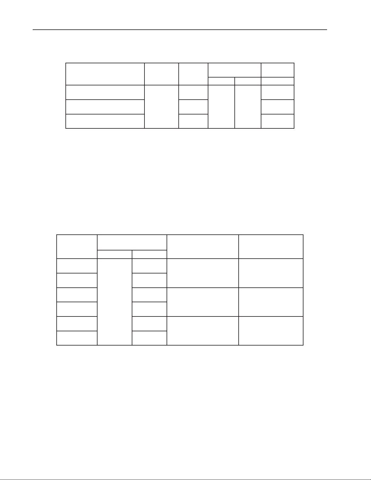
I. Specications
A. Nameplate Ratings
Design Pressure
(PSIG) Refrigerant
HIGH LOW R-134a
9.8
240 120
Model
RH1-SSE-FG/RH1-SSE-HG
RH1-SSE-FS/RH1-SSE-HS
RH2-SSE-FG/RH2-SSE-HG
RH2-SSE-FS/RH2-SSE-HS
RH3-SSE-FG/RH3-SSE-HG
RH3-SSE-FS/RH3-SSE-HS
AC Supply
Voltage Amperes
4.0
115/60/1
6.0 13.7
7.0 16.9
See the nameplate for electrical and refrigeration specications. The nameplate is located
on the right side wall of the cabinet interior.
Note: We reserve the right to make changes in specications and design without prior
notice.
B. Dimensions
1. Door Opening, Refrigerated Volume, and Shelf Space
a) Units: mm (in.).
b) Legs have 25.4 mm (1 in.) height adjustment.
Door Opening
Model
RH1-SSE-FG
RH1-SSE-FS
RH1-SSE-HG
RH1-SSE-HS
RH2-SSE-FG
RH2-SSE-FS
RH2-SSE-HG
RH2-SSE-HS
RH3-SSE-FG
RH3-SSE-FS
RH3-SSE-HG
RH3-SSE-HS
mm (in.)
Width Height
1,507 (59.3)
681.7 (26.8)
1,507 (59.3)
554 (21.8)
681.7 (26.8)
1,507 (59.3)
681.7 (26.8)
Total Refrigerated
Volume ft
3
22.3 11.5
48.3
73.7
Total Shelf Space
ft
25.3
39
2
Note: We reserve the right to make changes in specications and design without prior
notice.
6
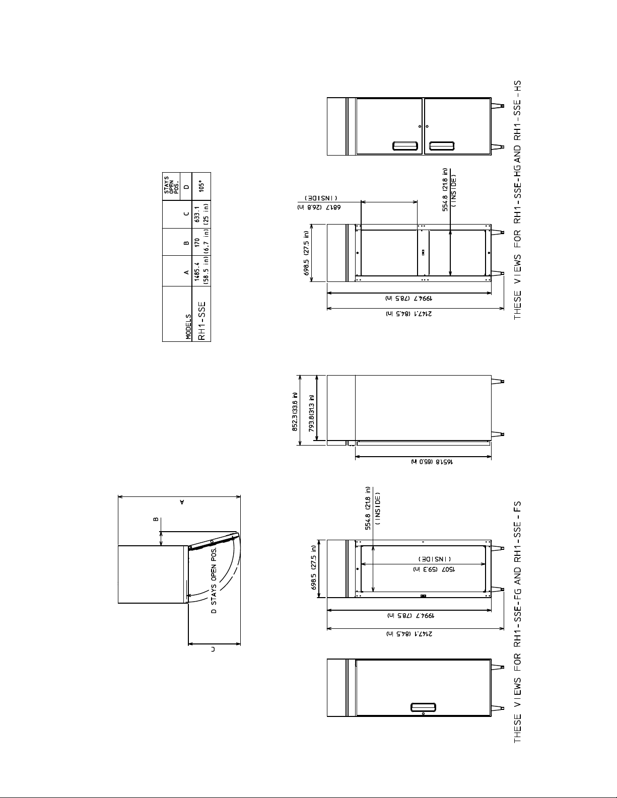
2. One Section
Unit: mm (in.)
7
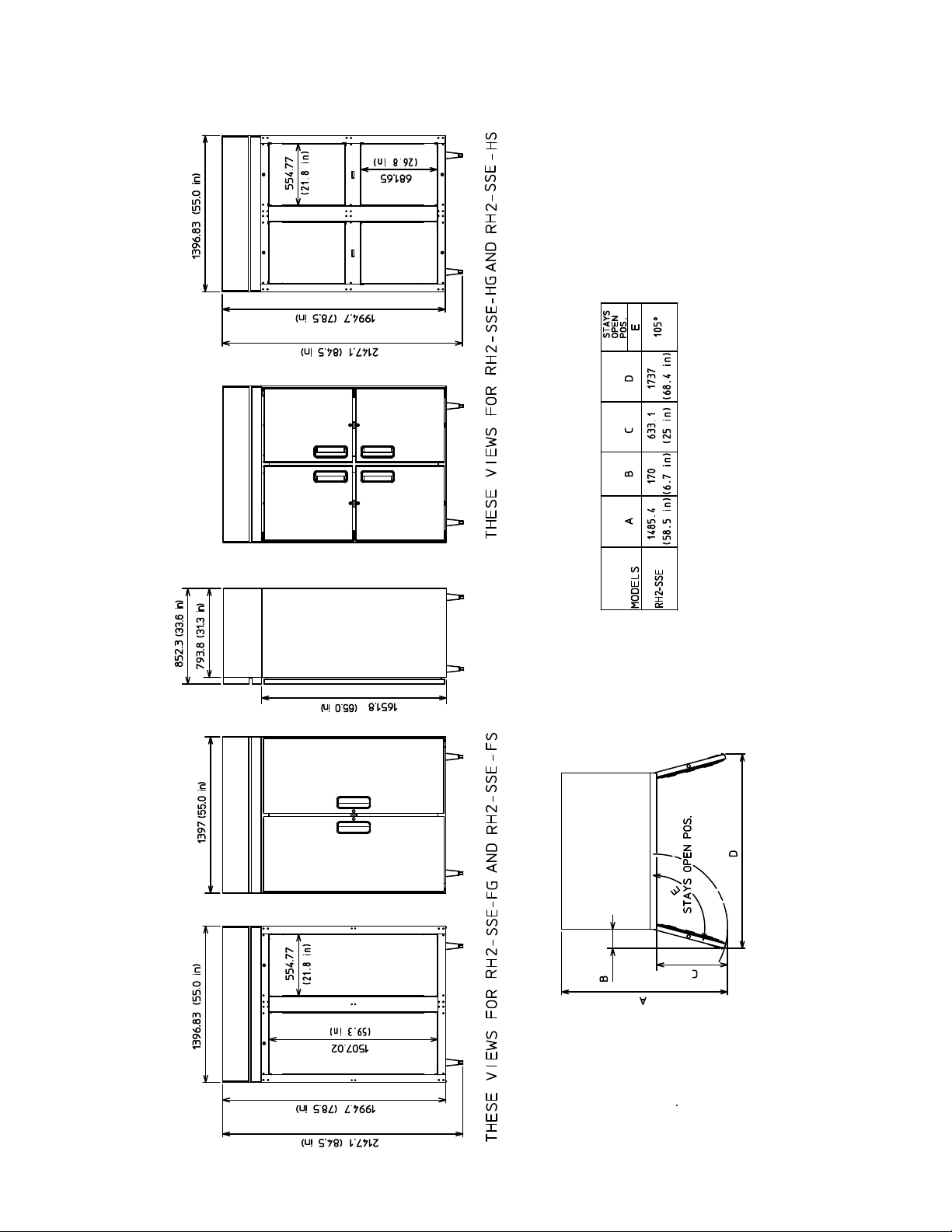
3. Two Section
Unit: mm (in.)
8
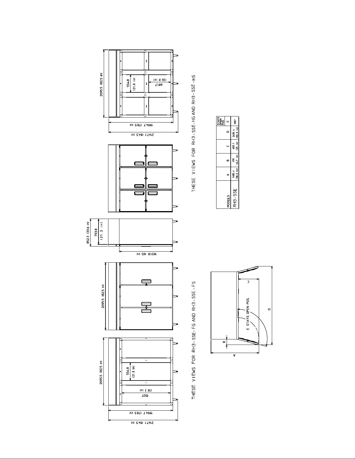
4. Three Section
Unit: mm (in.)
9
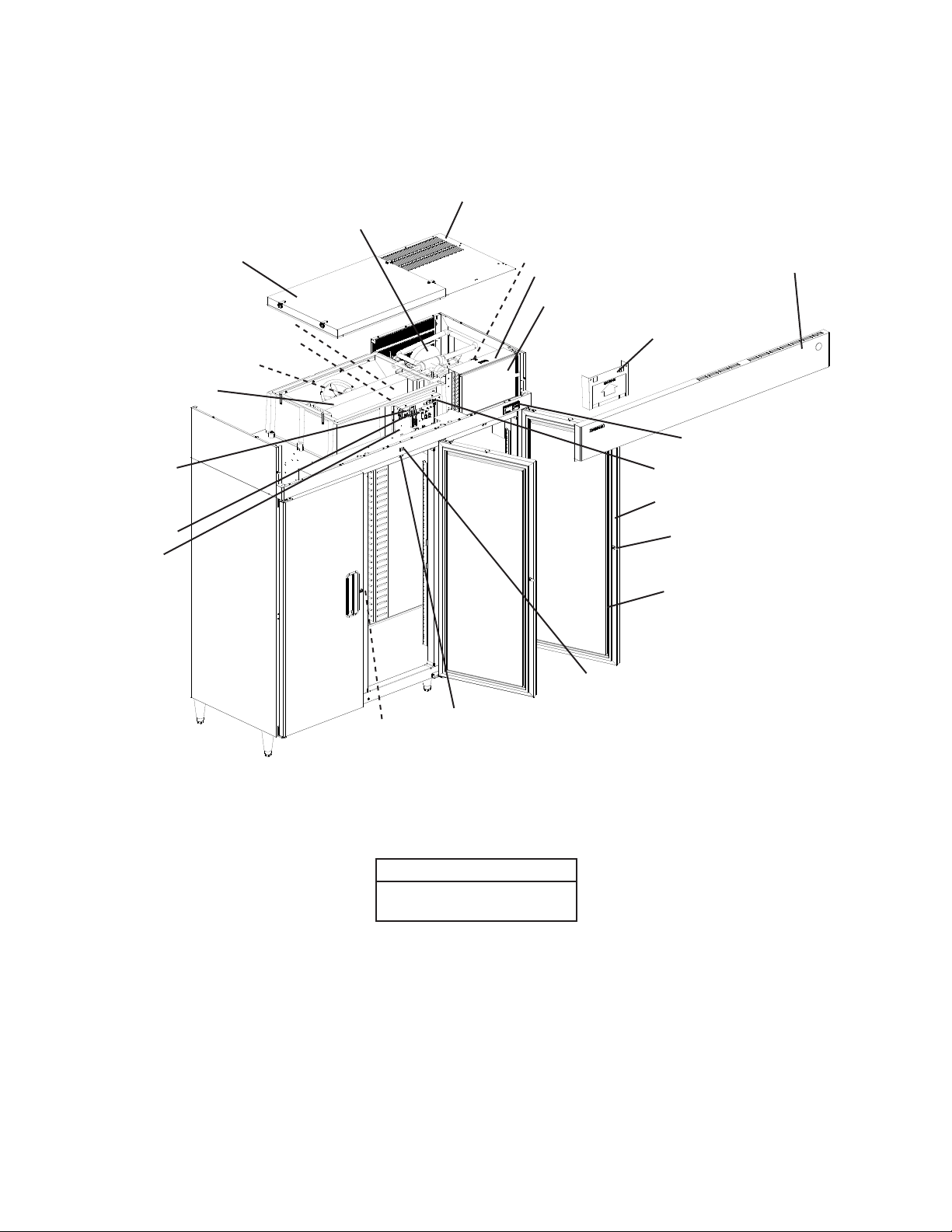
II. General Information
A. Construction
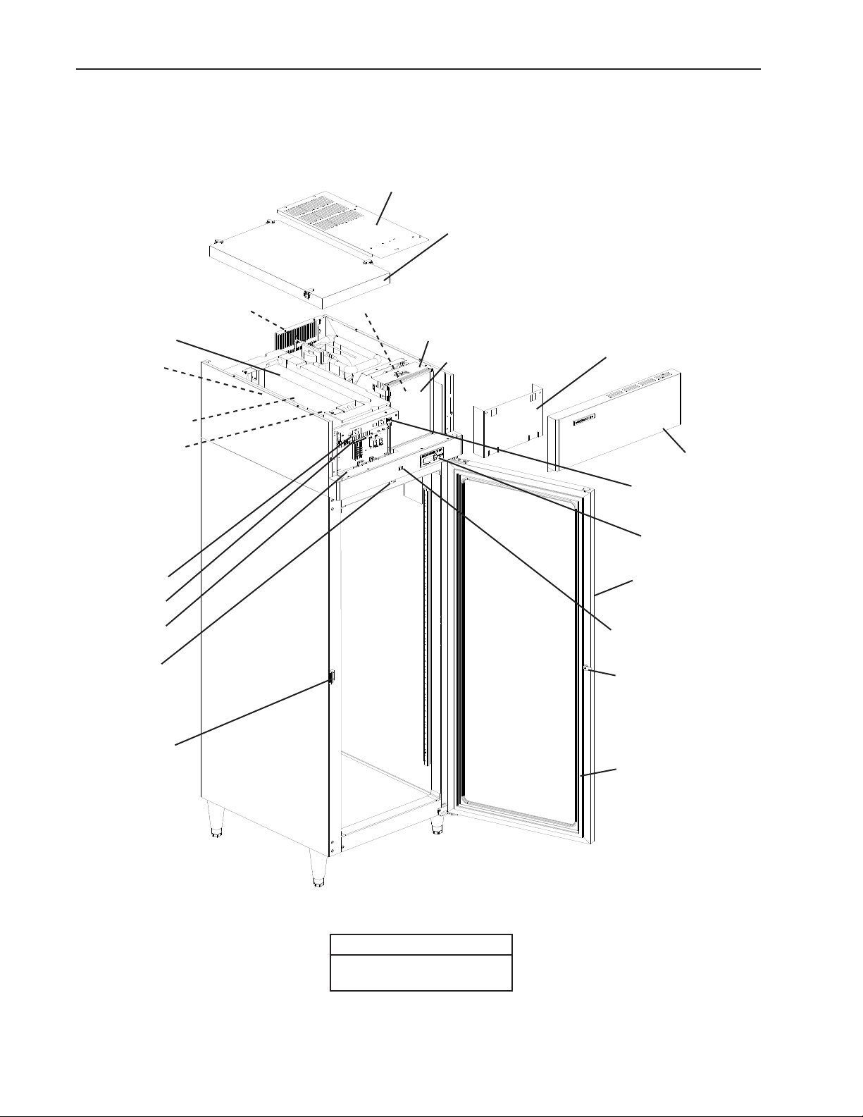
1. One Section
Compressor and
Compressor Electronic Unit
Top Cover
Evaporator Case Cover
Condenser Fan Motor
Evaporator
Evaporator
Fan Motor
Cabinet Thermistor
Defrost Thermistor
Power Switch
Control Board
Control Box
Door Switch
Condenser
Condenser Air Filter
Control Box Cover
Front Panel
Perimeter Heater
Switch
Display Board
Door
Light Switch
(glass door model)
Door Lock
Door Latch
Door Gasket
Model Shown: RH1-SSE-FG
Models
RH1-SSE-FG, RH1-SSE-HG
RH1-SSE-FS, RH1-SSE-HS
10
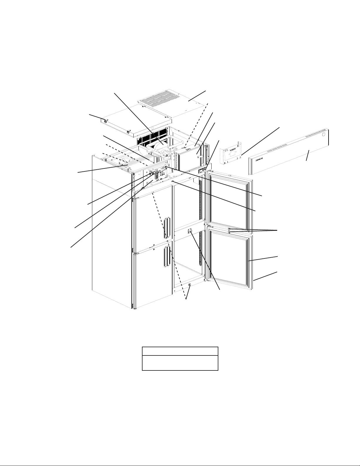
2. Two Section
Compressor and
Compressor Electronic Unit
Evaporator
Case Cover
Top Cover
Condenser Fan Motor
Condenser
Condenser Air Filter
Control Box Cover
Defrost Thermistor
Cabinet Thermistor
Evaporator Fan Motor
Evaporator
Power Switch
Control Board
Control Box
Display Board
Front Panel
Perimeter Heater
Switch
Light Switch
(glass door model)
Door Lock
Door Gasket
Door
Door Latch
Door Switch
Model Shown: RH2-SSE-HS
Models
RH2-SSE-FG, RH2-SSE-HG
RH2-SSE-FS, RH2-SSE-HS
11
3. Three Section
Compressor and Compressor Electronic Unit
Top Cover
Evaporator Case Cover
Defrost Thermistor
Cabinet Thermistor
Evaporator Fan Motor
Evaporator
Power Switch
Control Board
Control Box
Door Latch
Condenser Fan Motor
Door Switch
Condenser
Condenser Air Filter
Control Box Cover
Light Switch
(glass door model)
Front Panel
Display Board
Perimeter Heater Switch
Door
Door Lock
Door Gasket
Model Shown: RH3-SSE-FS
Models
RH3-SSE-FG, RH3-SSE-HG
RH3-SSE-FS, RH3-SSE-HS
12

B. Sequence of Operation
1. Sequence Cycles and Shutdown
The steps in the sequence are as outlined below.This unit utilizes a control board to
switch the components on and off as needed. When power is supplied and the power
switch is in the "ON" position, CB red "POWER OK" LED comes on and CB revision
(r###) appears on DB.
Note: 1. "POWER OK" LED remains on until the power switch is moved to the "OFF"
position, the power supply is turned off, or the unit is unplugged from the
electrical outlet.
2. There is a minimum 2.5-minute Comp on time and 2.5-minute Comp off time.
a) Startup
No Component LED on: EvapFM energizes. 2.5-minute Comp delay timer starts.
Cabinet temperature appears on DB.
b) Cool Down
LEDs 4 and 5 on: 2.5-minute Comp delay timer terminates, EvapFM continues,
Comp, ConFM, and PH energize.
c) Cool Down Achieved
No Component LED on: CB monitors cooling of the cabinet via CTh. CTh cools to
3°F (1.7°C) below setpoint. EvapFM continues, Comp, ConFM, and PH de-energize.
d) Cool Down Restart
LEDs 4 and 5 on: CTh warms to 3°F (1.7°C) above setpoint. EvapFM continues,
Comp, ConFM, and PH energize.
e) Defrost
LED 5 on:
(1a) Temperature-Initiated Defrost
DTh cools to 13°F (-10°C). Comp and PH, if energized, de-energize, EvapFM
continues. If energized, ConFM continues, otherwise, ConFM energizes. Cabinet
temperature is displayed on DB during defrost.
(1b) Optional Time-Initiated Defrost
The optional time-initiated defrost is factory set to 0 times per day. Before
changing this setting, contact Hoshizaki Technical Support at 1-800-233-1940 for
recommendations.
When set to greater than 0, defrost initiates when the defrost timer terminates. For
further details, see "II.D.5.b) Defrost Frequency."
(2) Defrost Termination
DTh warms to 40°F (4.4°C). EvapFM and ConFM continue. 2.5 minute delay
before Comp and PH energize.
Legend: CB–control board; ConFM–condenser fan motor; Comp–compressor;
CTh–cabinet thermistor; DB–display board; DTh–defrost thermistor;
EvapFM–evaporator fan motor; PH–perimeter heater
13
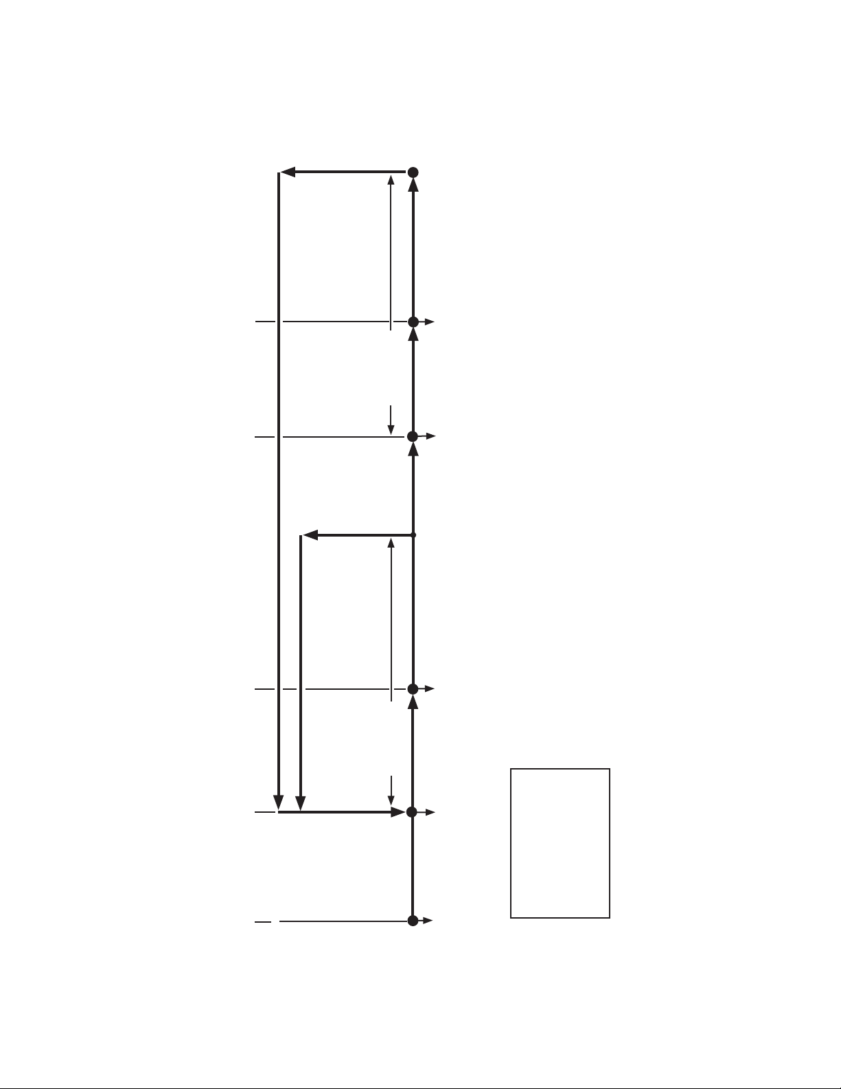
2. Sequence Flow Chart
5. Defrost Termination
4. Defrost
DTh warms to
40°F (4.4°C)
DTh cools to
13°F (-10°C) or
optional defrost
timer terminates
EvapFM continues
ConFM continues
DTh in control
EvapFM continues
ConFM continues
Comp de-energized
PH de-energized
CTh warms to
3°F (1.7°C)
above setpoint
Refrigerator Sequence Flow Chart
3. Cool Down Achieved
CTh cools to
3°F (1.7°C)
below setpoint
EvapFM continues
Comp de-energized
ConFM de-energized
PH de-energized
Note: Minimum 2.5-minute Comp on time and 2.5-minute Comp off time.
CTh in control
2. Cool Down
EvapFM continues
Comp energized
ConFM energized
PH energized
Legend:
EvapFM-cabinet fan motor
CTh-cabinet thermistor
Comp-compressor
ConFM-condenser fan motor
DTh-defrost thermistor
1. Startup
2.5-minute Comp
delay timer starts
EvapFM energized
PH-perimeter heater
14
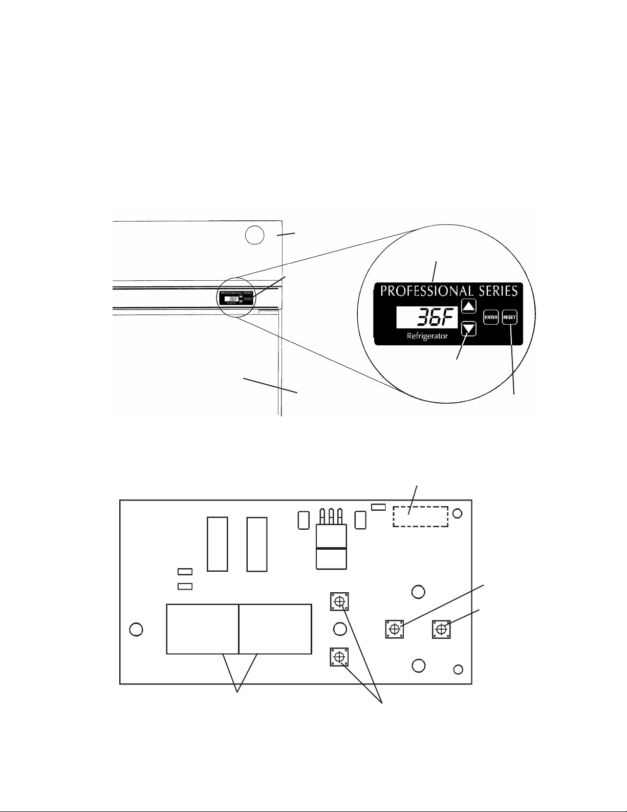
C. Display Board
When the power switch is moved to the "ON" position, the control board revision
appears on the display board. "r###" indicates the control board revision level (e.g.,
r23C). Afterward, the current cabinet temperature is displayed. The display board also
allows for access to the guarded access menu and service menu. From the guarded
access menu, the cabinet setpoint, defrost frequency, and temperature display scale can
be adjusted. For further details, see "II.D.5. Guarded Access Menu." From the service
menu, information regarding unit functions can be obtained. For further details, see
"II.D.6. Service Menu."
Display Board
Front Panel
Display Board
Door
Fig. 1
Display
Board
Up and Down
Buttons
"RESET" Button:
Temporarily
silences audible
alarms
Ribbon Cable Connector
LED Display
Fig. 2
15
P/N 2A0883-01
Up and Down Buttons
"ENTER" Button
"RESET" Button
 Loading...