

Hoshizaki American, Inc. Reach-In, Roll-In, Pass-Thru, Roll-Thru Installation Manual
Hoshizaki America, Inc.
Hoshizaki
Professional Series
Refrigerated Kitchen Equipment
“A Superior Degree
of Reliability”
www.hoshizaki.com
Models
Reach-In
Roll-In
Pass-Thru
Roll-Thru
INSTRUCTION MANUAL
Issued: 11-3-2009
Revised: 9-1-2010

IMPORTANT
Only qualied service technicians should install, service, and maintain the
unit. No installation, service, or maintenance should be undertaken until
the technician has thoroughly read this Instruction Manual. Likewise, the
owner/manager should not proceed to operate the unit until the installer has
instructed them on its proper operation. Failure to install, operate, and maintain
the equipment in accordance with this manual may adversely affect safety,
performance, component life, and warranty coverage.
Hoshizaki provides this manual primarily to assist qualied service technicians in the
installation, maintenance, and service of the unit.
Should the reader have any questions or concerns which have not been satisfactorily
addressed, please call, write, or send an e-mail message to the Hoshizaki Technical
Support Department for assistance.
HOSHIZAKI AMERICA, INC.
618 Highway 74 South
Peachtree City, GA 30269
Attn: Hoshizaki Technical Support Department
Phone: 1-800-233-1940 Technical Support
(770) 487-2331
Fax: 1-800-843-1056
(770) 487-3360
E-mail: techsupport@hoshizaki.com
Web Site: www.hoshizaki.com
NOTE: To expedite assistance, all correspondence/communication MUST include the
following information:
• Model Number
• Serial Number
• Complete and detailed explanation of the problem.
2

IMPORTANT
This manual should be read carefully before the unit is installed and operated.
Only qualied service technicians should install, service, and maintain the unit.
Read the warnings contained in this booklet carefully as they give important
information regarding safety. Please retain this booklet for any further reference
that may be necessary.
CONTENTS
Important Safety Information ................................................................................................. 5
I. Installation Instructions ....................................................................................................... 6
A. Location ........................................................................................................................ 6
B. Checks Before Installation ............................................................................................. 6
C. Setup ............................................................................................................................. 7
1. Remove the Unit from the Pallet ............................................................................... 7
2. Optional Overow Pan Installation (if applicable) .................................................... 7
a) Reach-In Optional Overow Pan (HS-3521) ...................................................... 7
b) Pass-Thru Optional Overow Pan (HS-3560) .................................................... 7
3. RFH1-SSB-HS Lower Condensate Pan Installation ................................................. 8
D. Electrical Connection ...................................................................................................11
E. Front Panel .................................................................................................................. 12
F. Door Reversal .............................................................................................................. 13
G. Final Checklist ............................................................................................................ 13
II. Operating Instructions ...................................................................................................... 14
A. Operation ................................................................................................................... 14
B. Startup ........................................................................................................................ 15
C. Cabinet Temperature ................................................................................................... 16
1. Temperature Display ............................................................................................... 16
2. Adjusting the Temperature Setpoint ....................................................................... 16
3. Changing the Temperature Display Scale (°F or °C) ............................................. 16
D. Defrost ......................................................................................................................... 17
1. Refrigerator ............................................................................................................ 17
2. Freezer .................................................................................................................. 17
E. Food Storage............................................................................................................... 18
F. Perimeter Frame Heater............................................................................................... 18
G. Safety Devices ............................................................................................................ 19
1. Compressor External and Internal Overloads ........................................................ 19
2. Short-Cycle Protection ........................................................................................... 19
3. High-Pressure Switch ............................................................................................ 19
H. Alarm Safeties ............................................................................................................. 19
I. Cooling Performance .................................................................................................... 21
J. Cabinet Condensation ................................................................................................. 21
3

III. Cleaning and Maintenance Instructions .......................................................................... 22
A. Cleaning ...................................................................................................................... 22
1. Exterior ................................................................................................................... 22
2. Cabinet Interior ...................................................................................................... 22
3. Door Gaskets ......................................................................................................... 22
4. Shelves .................................................................................................................. 22
5. Glass Door ............................................................................................................. 22
B. Maintenance ................................................................................................................ 23
1. Air Filter .................................................................................................................. 23
2. Condenser ............................................................................................................. 23
3. Power Supply Connection ...................................................................................... 23
C. Shutdown and Long Storage ....................................................................................... 23
4
Important Safety Information
Throughout this manual, notices appear to bring your attention to situations which could
result in death, serious injury, or damage to the unit.
WARNING Indicates a hazardous situation which could result in death or
serious injury.
CAUTION Indicates a situation which could result in damage to the unit.
IMPORTANT Indicates important information about the use and care of the
unit.
WARNING
This unit should be destined only to the use for which it has been expressly
conceived. Any other use should be considered improper and therefore
dangerous. The manufacturer cannot be held responsible for injury or damage
resulting from improper, incorrect, and unreasonable use.
To reduce the risk of death, electric shock, serious injury, or re, follow
basic precautions including the following:
• Make sure the power switch is in the "OFF" position before making any
electrical connections, plugging in, or unplugging the unit to reduce the risk
of electric shock.
• Electrical connection must meet national, state, and local electrical code
requirements. Failure to meet these code requirements could result in death,
electric shock, serious injury, re, or severe damage to equipment.
• This unit requires an independent power supply. See the nameplate for proper
voltage and breaker/fuse size. Failure to use a proper breaker or fuse can
result in a tripped breaker, blown fuse, or damage to existing wiring. This
could lead to heat generation or re.
• THIS UNIT MUST BE GROUNDED. Failure to properly ground this unit could
result in death or serious injury. Corded Units: Corded units are equipped
with a 3-prong grounding plug to reduce the risk of potential shock hazards.
It must be plugged into a properly grounded, independent 3-prong wall outlet.
If the outlet is a 2-prong outlet, it is your personal responsibility to have a
qualied electrician replace it with a properly grounded, independent 3-prong
wall outlet. Do not remove the ground prong from the power cord and do not
use an adapter plug.
• Do not use an extension cord.
• Do not use a unit with a damaged power cord. The power cord should not be
altered, jerked, bundled, weighed down, pinched, or tangled. Such actions
could result in electric shock or re. To unplug the unit, be sure to pull the
plug, not the cord, and do not jerk the cord.
• To reduce the risk of electric shock, do not touch the plug or power switch
with damp hands.
• This unit should be disassembled or repaired only by qualied service
personnel to reduce the risk of electric shock, injury, or re.
• Do not make any alterations to the unit. Alterations could result in electric
shock, injury, re, or damage to the unit.
5
I. Installation Instructions
WARNING
1. This unit must be installed in accordance with all applicable national, state,
and local regulations.
2. Unit is heavy. Use care when lifting or positioning. Work in pairs when
needed to prevent injury or damage. Do not tilt the unit more than 45°.
A. Location
WARNING
This unit is not intended for outdoor use. Normal operating ambient
temperature should be within 45°F to 100°F (7°C to 38°C). Operation of the
unit, for extended periods, outside of this normal temperature range may affect
unit performance.
For best operating results:
• The unit should not be located next to ovens, grills, or other high heat producing
equipment.
• The location should provide a rm and level foundation for the unit.
• The unit should not be located in a corrosive environment.
• The unit should be a minimum of 4" (11 cm) from side walls. More clearance may be
necessary depending on the door combination of the unit.
• A minimum of 10" (25 cm) overhead clearance should be provided for proper ventilation.
B. Checks Before Installation
WARNING
Refer to the nameplate for electrical specications. The nameplate is located on
the right side wall of the cabinet interior. For more electrical connection details,
see "I.D. Electrical Connection." We reserve the right to make specication and
design changes without prior notice.
• Visually inspect the exterior of the shipping package and immediately report any damage
to the carrier. Upon opening the package, any concealed damage should also be
immediately reported to the carrier.
• Remove the shipping carton, tape, and packing material. Also remove the protective
plastic lm from both the exterior panels and the interior door panel. If the unit is exposed
to the sun or to heat, remove the lm after the unit cools.
• Remove all accessory containers before discarding the packing materials. Dispose of all
packing materials in a proper and environmentally responsible manner.
• Check for missing or damaged accessories.
6
C. Setup
1. Remove the Unit from the Pallet
1) Move as close to the nal location as possible.
2) Remove the 2 bolts securing the unit to the pallet, then remove the unit from the pallet.
Block the unit securely at a height of 8" (20 cm) off the oor. Do not lay the unit down.
3) Attach the adjustable legs or casters to the bottom of the unit. Locking casters should be
attached to the front of the unit.
2. Optional Overow Pan Installation (if applicable)
Optional overow pan kits are available for the unlikely event that water cannot
evaporate from the condensate pan at a high enough rate.
a) Reach-In Optional Overow Pan (HS-3521)
Tab
Reach-In Series
1) Attach the overow pan brackets by
engaging the tabs on the brackets through
the holes in the bottom of the unit and
securing with the 4 mounting screws
provided. See Fig. 1.
2) Slide the plastic overow pan into place
under the vinyl hose on the back of the
cabinet.
Overow Pan
Bracket
Cabinet
Fig. 1
Overow Pan
Bracket
Mounting
Screws
Mounting
Screws
Overow
Pan
b) Pass-Thru Optional Overow Pan (HS-3560)
1) Attach the overow pan brackets by engaging the tabs on the brackets through the holes
in the bottom of the unit and securing with the 2 mounting screws provided. See Fig. 2.
2) Slide the plastic overow pan into place under the vinyl hose on the side of the cabinet.
Pass-Thru Series
Left Bracket
Tab Holes
Tab Holes
Mounting Screw
Fig. 2
7
Overow Pan
Vinyl Hose
Right Bracket
Mounting Screw
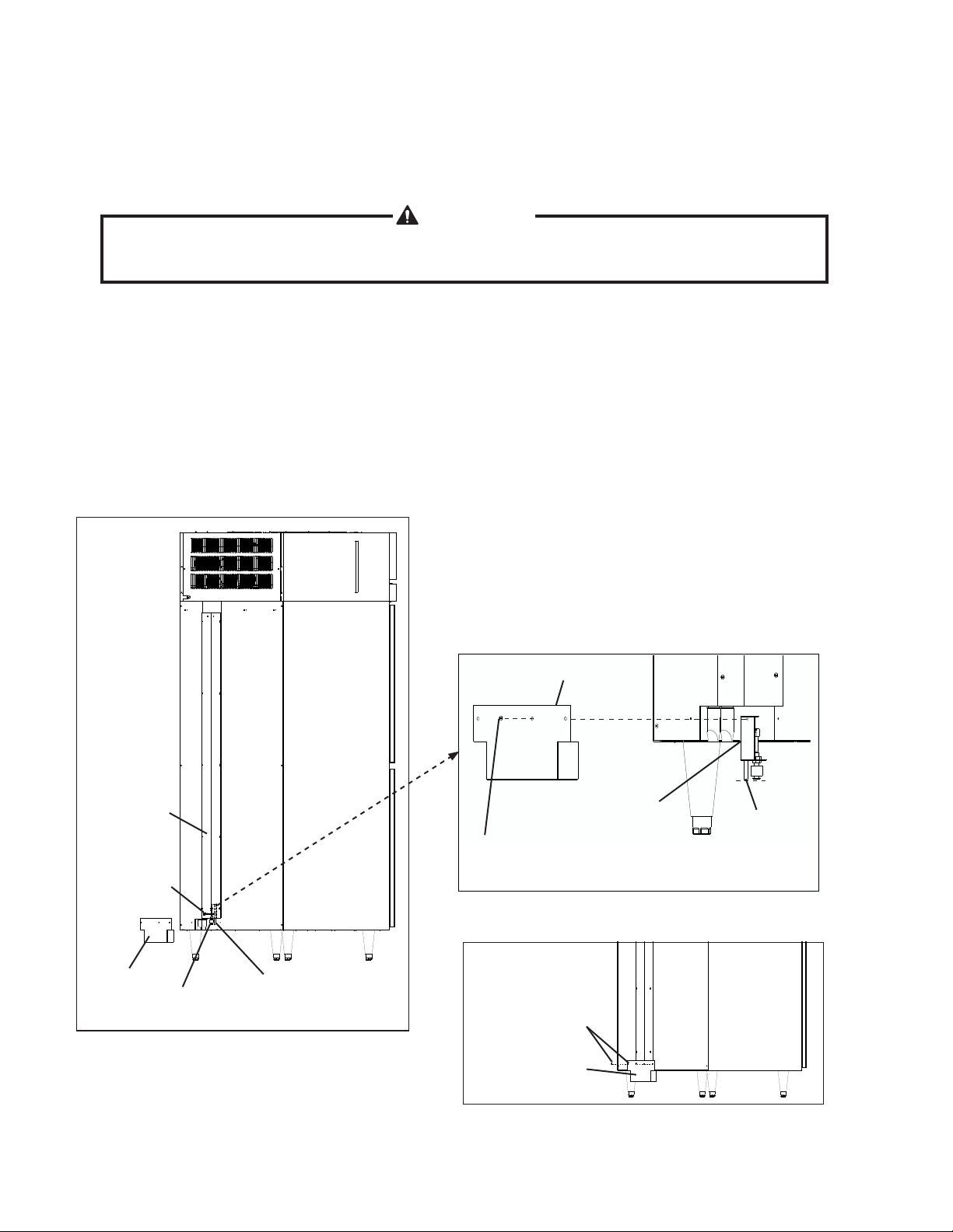
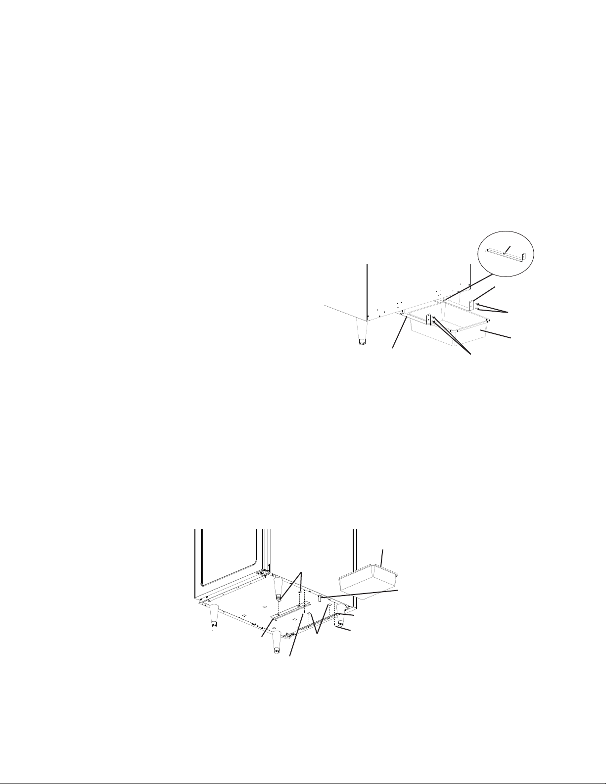
3. RFH1-SSB-HS Lower Condensate Pan Installation
The lower condensate pan collects condensate water from the evaporators of both the
refrigerator and freezer. When the lower condensate pan is full, the oat switch activates
the condensate pump. Condensate water is pumped into the upper condensate pan for
evaporation.
WARNING
Verify that power to the unit is disconnected before installing the lower
condensate pan.
1) Remove the nylon tie securing the oat switch assembly to the rear cover. Pull the oat
switch assembly down below the rear cover. See Fig. 3.
2) Rotate the oat switch assembly 180° degrees. Using 1 of the screws provided, attach
the oat switch assembly to the condensate pan. See Fig. 4.
3) Using the remaining 2 screws provided, mount the lower condensate pan to the rear of
the unit. See Fig. 5. CAUTION! Conrm that the vinyl hose is even with the bottom
of the oat switch before attaching the condensate pan to the unit.
4) Plug the unit in.
Rear Cover
Nylon Tie
Condensate
Pan
Float Switch
Assembly
Fig. 3
Vinyl Hose
Condensate Pan
Rotate Float Switch
Assembly 180° degrees
Float Switch Assembly
Mounting Screw
Fig. 4
Condensate Pan
Mounting Screws
Condensate Pan
Vinyl
Hose
Fig. 5
8
 Loading...