

Hoshizaki American, Inc. KML-631MAH, KML-631MWH, KML-631MRH Part Manual
Hoshizaki
Hoshizaki America, Inc.
Low-Profile Modular Crescent Cuber
Models
KML-631MAH
“A Superior Degree
of Reliability”
www.hoshizaki.com
KML-631MWH
KML-631MRH
PARTS LIST
™
Number: 71263
Issued: 5-1-2007
Revised: 2-1-2011

CONTENTS
Auxiliary.................................................................................................................................. 3
Note About Ordering Parts .................................................................................................... 3
Material Abbreviations ........................................................................................................... 4
A. Ice Cuber Assembly .......................................................................................................... 5
KML-631MAH .................................................................................................................... 5
KML-631MWH ................................................................................................................... 8
KML-631MRH .................................................................................................................. 10
B. Refrigeration Circuit ......................................................................................................... 12
KML-631MAH .................................................................................................................. 12
KML-631MWH ................................................................................................................. 16
KML-631MRH .................................................................................................................. 20
C. Water Circuit .................................................................................................................... 24
D. Control Box Assembly ...................................................................................................... 28
E. Label Location ................................................................................................................. 31
KML-631MAH .................................................................................................................. 31
KML-631MWH ................................................................................................................. 33
KML-631MRH .................................................................................................................. 35
F. Top Panel Assembly ......................................................................................................... 37
G. Front Panel Assembly ..................................................................................................... 38
H. Accessories ..................................................................................................................... 39
2

Auxiliary Codes
KML-631MAH S-0 May 2007
S-2 December 2007
T-0 January 2008
U-0 January 2009
U-1 July 2009
V-0 January 2010
V-1 July 2010
A-0 January 2011
KML-631MWH S-0 November 2007
T-0 February 2008
U-0 March 2009
U-1 July 2009
V-0 January 2010
V-1 July 2010
A-0 January 2011
KML-631MRH S-0 May 2007
S-2 December 2007
T-0 February 2008
U-0 January 2009
U-1 July 2009
V-0 January 2010
V-1 July 2010
A-0 January 2011
Auxiliary Code Breakdown
The auxiliary code is the rst two characters in the serial number. The rst character
indicates the year. Years progress or regress in alphabetical order. The series runs from
"A" through "V" and the letters "I" and "O" are skipped. The second character indicates
signicant part changes within a year. Base is "0" and this number advances for each
change. In cases where there is a letter in parentheses, this designates the month. This is
the last character in the serial number. The series runs from "(A)" through "(M)" and the
letter "(I)" is skipped. This designation is only included when identifying a parts change
within an auxiliary code.
Note About Ordering Parts
Most assemblies cannot be ordered as complete units; parts in the assemblies generally
must be ordered separately.
3

Material Abbreviations
ALUMINUM
AL = Aluminum
COPPER
CU = Copper
PLASTIC
ABS = Acrylonitrile -butadiene - styrene
AC = Polyacetal
EVA = Ethylene vinyl acetate
PA = Polyamide = Nylon
PC = Polycarbonate
PE = Polyethylene
PES = Polyester
PETP = Polyethylene terephthalate = Tetlon
PP = Polypropylene
PS = Polystyrene
PTFE = Polytetrauoroethylene = Teon
PUR = Polyurethane
PVC = Polyvinyl chloride
RUBBER
VN = Vinyl Nitrile
EPDM = EP rubber
NBR = Nitrile butadiene rubber
NR = Natural rubber
NP = Neoprene
SI.R = Silicone rubber
SY.R = Synthetic rubber
EPH = Epichlorohydrin
STEEL
GS = Galvanized steel
SS = Stainless steel
PS = Plated steel
PAS = Primed steel
4
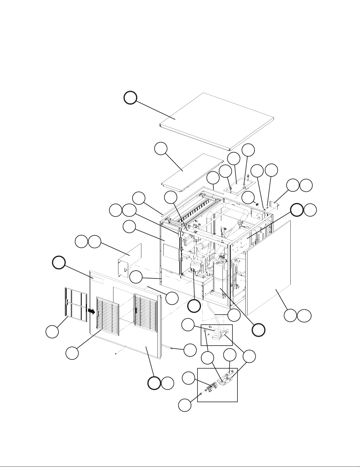
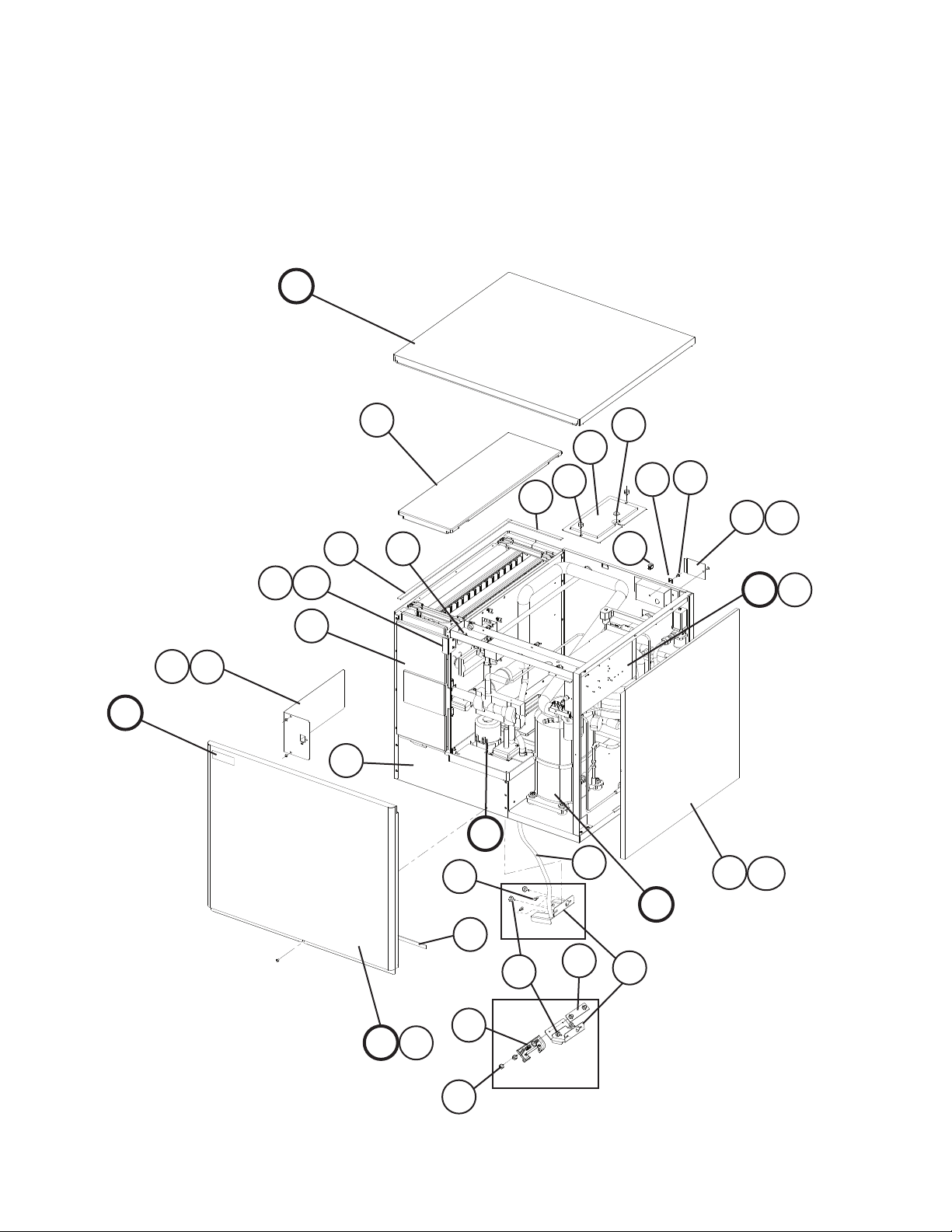
A. Ice Cuber Assembly
KML-631MAH
S-0 to A-0
F
17
E
15
11
20
22
21
14a
14
12
2a
2
1
19
16
10
9
4
3
5a
5
18
D1
D
C
24
7
13
13a
B
S-0
23
8
27
6
G
G1
25
S-2 and later
26
5
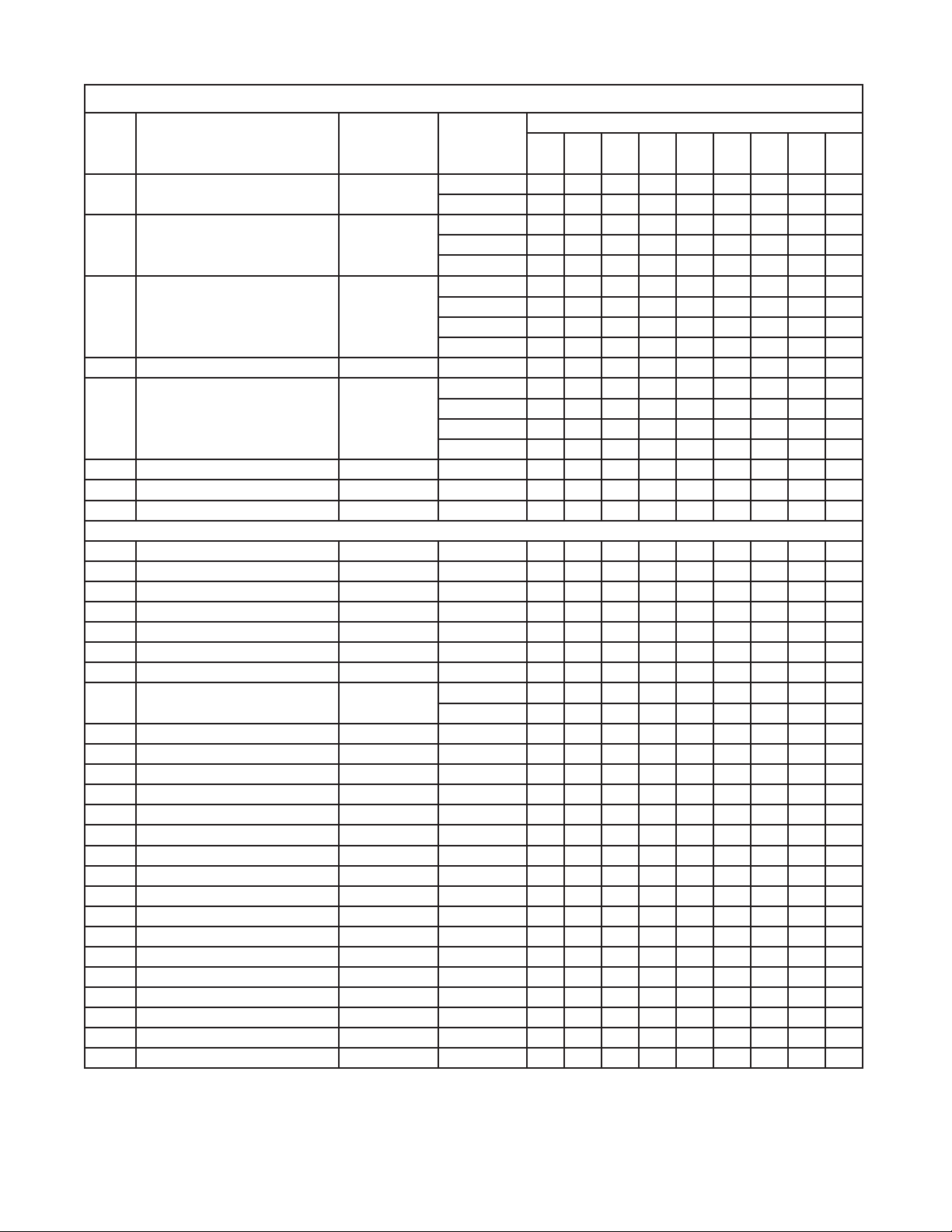
Title: A. Ice Cuber Assembly Model: KML-631MAH
Required Number
Index
No. Description
B Refrigeration Circuit - 1A1204A01 1 1 1 1 -
C Water Circuit - 2A3840A01 1 1 -
D Control Box Assembly - 2A3846A01 1 1 -
D1 T2 Screw 4×8 7P31-0408 3 3 3 3 3 3
E Label Location - 3A3989A01 1 1 -
F Top Panel Assembly - 3A1862A01 1 1 1 1 1 1
G Front Panel Assembly - 3A4001A01 1 1 1 1 1 1
G1 Truss Head Screw 4×8, SS 7C32-0408 1 1 1 1 1 1
1 Evaporator Case - 2A3841G01 1 1 1 1 1 1
2 Control Box Cover GS 3A2371-01 1 1 1 1 1 1
2a T2 Screw 4×8 7P31-0408 3 3 3 3 3 3
3 Square Washer BRASS 433537-02 1 1 1 1 1 1
4 Grounding Screw BRASS 433304-02 1 1 1 1 1 1
5 Junction Box Cover GS 433410-01 1 1 1 1 1 1
5a T2 Screw 4×8 7P31-0408 1 1 1 1 1 1
6 Thermostat Extension Bracket SS 4A3436-01 1 -
7 Spacer PE 443545-01 2 -
8 Thumbscrew SS, ABS 415949G10 2 2 2 2 2 2
9 Bin Control Cover GS 3A0664G01 1 1 1 1 1 1
10 Capillary Ring EP RUBBER 425307-01 1 1 1 1 1 1
11 Top Insulation PP 215730G01 1 1 1 1 1 1
12 Front Insulation PP 2A0664G02 1 1 1 1 1 1
13 Side Panel (R) SS 2A2114G01 1 1 1 1 1 1
13a T2 Screw 4×8, SS 7P32-0408 1 1 1 1 1 1
14 Barrier - Insulation GS 4A1167-01 1 1 1 1 1 1
14a T2 Screw 4×8 7P31-0408 2 2 2 2 2 2
15 Louver ABS 1A0548-01 2 2 2 2 2 2
16 Push Retainer - 4A2414-01 6 6 6 6 6 6
17 Air Filter - 2A2063G01 2 2 2 2 2 2
18 Bushing SR-30-1 420472-03 1 1 1 1 1 1
19 Wire Saddle VWS4238-C 4A0338-02 2 2 2 2 2 2
20 Thumbscrew SS, ABS 415949G08 2 2 2 2 2 2
21 Gasket L=655 4A0808L02 2 2 2 2 2 2
Material or
Model Number Part Number
1A1910A01 1 1
2A3840A02 1 2A3840A03 1 1 1
2A3846A03 1 2A3846A05 1 1 2A3846A07 1
3A4845A01 1 3A5871A01 1 1 3A5871A02 1
4A4358-01 1 1 1 1 1
S-0 S-2
T- 0
U-0 U-1 V- 0
V-1
A-0
6
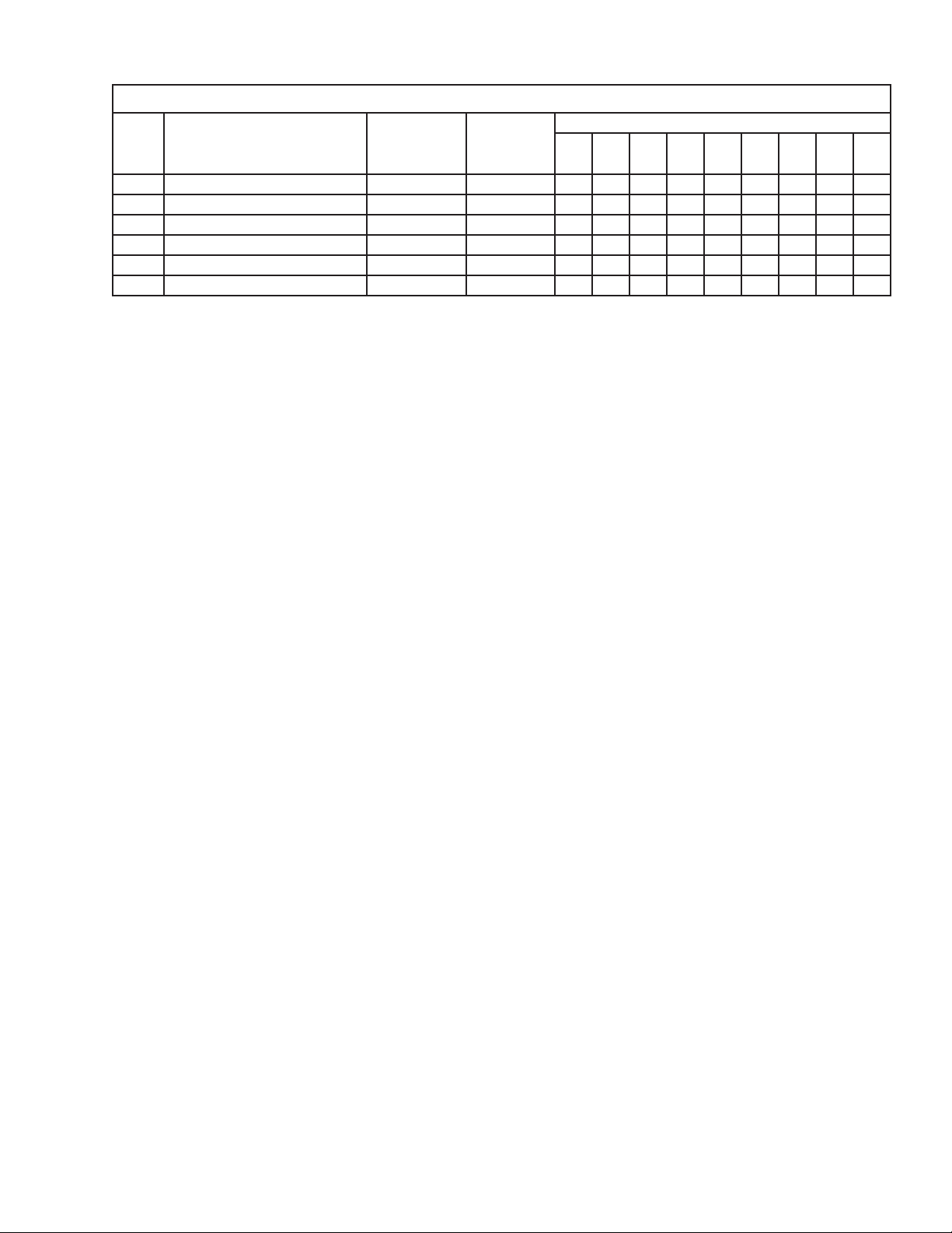
Title: A. Ice Cuber Assembly Model: KML-631MAH
Required Number
Index
No. Description
22 Gasket L=190 4A0808L02 1 1 1 1 1 1
23 Gasket L=762 4A0808L02 1 1 1 1 1 1
24 Silicone Hose L=310 7730I3812 1 1 1 1 1 1
25 Bulb Holder - 3A3903-01 1 1 1 1 1
26 Thumbscrew SS, ABS 415949G11 2 2 2 2 2
27 NSF Plate - 4A4401G01 1 1 1 1 1
Material or
Model Number Part Number
S-0 S-2
T- 0
U-0 U-1 V- 0
V-1
A-0
7
A. Ice Cuber Assembly
KML-631MWH
S-0 to A-0
F
E
11
17
19
18
14a
14
12
2a
2
1
16
10
9
4
3
5a
5
15
D1
D
C
7
21
13
13a
G
G1
23
20
22
8
S-0
8
T-0 and later
24
B
6
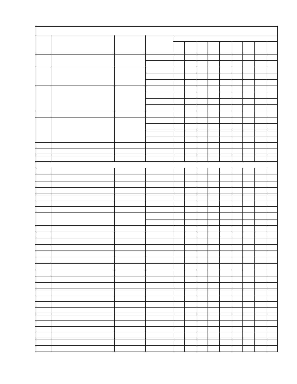
Title: A. Ice Cuber Assembly Model: KML-631MWH
Required Number
Index
No. Description
B Refrigeration Circuit - 1A1205A01 1 1 1 -
C Water Circuit - 2A3840A01 1 -
D Control Box Assembly - 2A3846A02 1 -
D1 T2 Screw 4×8 7P31-0408 3 3 3 3 3
E Label Location - 3A3990A01 1 -
F Top Panel Assembly - 3A1862A01 1 1 1 1 1
G Front Panel Assembly - 3A4001A02 1 1 1 1 1
G1 Truss Head Screw 4×8, SS 7C32-0408 1 1 1 1 1
1 Evaporator Case - 2A3841G01 1 1 1 1 1
2 Control Box Cover GS 3A2371-01 1 1 1 1 1
2a T2 Screw 4×8 7P31-0408 3 3 3 3 3
3 Square Washer BRASS 433537-02 1 1 1 1 1
4 Grounding Screw BRASS 433304-02 1 1 1 1 1
5 Junction Box Cover GS 433410-01 1 1 1 1 1
5a T2 Screw 4×8 7P31-0408 1 1 1 1 1
6 Thermostat Extension Bracket SS 4A3436-01 1 -
7 Spacer PE 443545-01 2 8 Thumbscrew SS, ABS 415949G10 2 2 2 2 2
9 Bin Control Cover GS 3A0664G01 1 1 1 1 1
10 Capillary Ring EP RUBBER 425307-01 1 1 1 1 1
11 Top Insulation PP 215730G01 1 1 1 1 1
12 Front Insulation PP 2A0664G02 1 1 1 1 1
13 Side Panel (R) SS 2A2114G01 1 1 1 1 1
13a T2 Screw 4×8, SS 7P32-0408 1 1 1 1 1
14 Barrier - Insulation GS 4A1167-01 1 1 1 1 1
14a T2 Screw 4×8 7P31-0408 2 2 2 2 2
15 Bushing SR-30-1 420472-03 1 1 1 1 1
16 Wire Saddle VWS4238-C 4A0338-02 2 2 2 2 2
17 Thumbscrew SS, ABS 415949G08 2 2 2 2 2
18 Gasket L=655 4A0808L02 2 2 2 2 2
19 Gasket L=190 4A0808L02 1 1 1 1 1
20 Gasket L=762 4A0808L02 1 1 1 1 1
21 Silicone Hose L=310 7730I3812 1 1 1 1 1
22 Bulb Holder - 3A3903-01 1 1 1 1
23 Thumbscrew SS, ABS 415949G11 2 2 2 2
24 NSF Plate - 4A4401G01 1 1 1 1
Material or
Model Number Part Number
1A1911A01 1 1
2A3840A02 1 2A3840A03 1 1 1
2A3846A04 1 2A3846A06 1 1 2A3846A08 1
3A4846A01 1 3A5872A01 1 1 3A5872A02 1
4A4358-01 1 1 1 1
T- 0
S-0
U-0 U-1 V- 0
V-1
A-0
9
A. Ice Cuber Assembly
KML-631MRH
S-0 to A-0
F
E
11
17
19
18
14a
14
12
2a
2
1
16
10
9
4
3
5a
5
15
D1
D
C
7
21
13
13a
G
G1
23
10
20
22
S-0
8
S-2 and later
24
B
6

Title: A. Ice Cuber Assembly Model: KML-631MRH
Required Number
Index
No. Description
B Refrigeration Circuit - 1A1206A01 1 1 1 1 -
C Water Circuit - 2A3840A01 1 1 -
D Control Box Assembly - 2A3846A02 1 1 -
D1 T2 Screw 4×8 7P31-0408 3 3 3 3 3 3
E Label Location - 3A3991A01 1 1 -
F Top Panel Assembly - 3A1862A01 1 1 1 1 1 1
G Front Panel Assembly - 3A4001A02 1 1 1 1 1 1
G1 Truss Head Screw 4×8, SS 7C32-0408 1 1 1 1 1 1
1 Evaporator Case - 2A3841G01 1 1 1 1 1 1
2 Control Box Cover GS 3A2371-01 1 1 1 1 1 1
2a T2 Screw 4×8 7P31-0408 3 3 3 3 3 3
3 Square Washer BRASS 433537-02 2 2 2 2 2 2
4 Grounding Screw BRASS 433304-02 2 2 2 2 2 2
5 Junction Box Cover GS 433410-01 2 2 2 2 2 2
5a T2 Screw 4×8 7P31-0408 2 2 2 2 2 2
6 Thermostat Extension Bracket SS 4A3436-01 1 -
7 Spacer PE 443545-01 2 -
8 Thumbscrew SS, ABS 415949G10 2 2 2 2 2 2
9 Bin Control Cover GS 3A0664G01 1 1 1 1 1 1
10 Capillary Ring EP RUBBER 425307-01 1 1 1 1 1 1
11 Top Insulation PP 215730G01 1 1 1 1 1 1
12 Front Insulation PP 2A0664G02 1 1 1 1 1 1
13 Side Panel (R) SS 2A2114G01 1 1 1 1 1 1
13a T2 Screw 4×8, SS 7P32-0408 1 1 1 1 1 1
14 Barrier - Insulation GS 4A1167-01 1 1 1 1 1 1
14a T2 Screw 4×8 7P31-0408 2 2 2 2 2 2
15 Bushing SR-30-1 420472-03 2 2 2 2 2 2
16 Wire Saddle VWS4238-C 4A0338-02 2 2 2 2 2 2
17 Thumbscrew SS, ABS 415949G08 2 2 2 2 2 2
18 Gasket L=655 4A0808L02 2 2 2 2 2 2
19 Gasket L=190 4A0808L02 1 1 1 1 1 1
20 Gasket L=762 4A0808L02 1 1 1 1 1 1
21 Silicone Hose L=310 7730I3812 1 1 1 1 1 1
22 Bulb Holder - 3A3903-01 1 1 1 1 1
23 Thumbscrew SS, ABS 415949G11 2 2 2 2 2
24 NSF Plate - 4A4401G01 1 1 1 1 1
Material or
Model Number Part Number
1A1912A01 1 1
2A3840A02 1 2A3840A03 1 1 1
2A3846A04 1 2A3846A06 1 1 2A3846A09 1
3A4847A01 1 3A5873A01 1 1 3A5873A02 1
4A4358-01 1 1 1 1 1
S-0 S-2
T- 0
U-0 U-1 V- 0
V-1
A-0
11
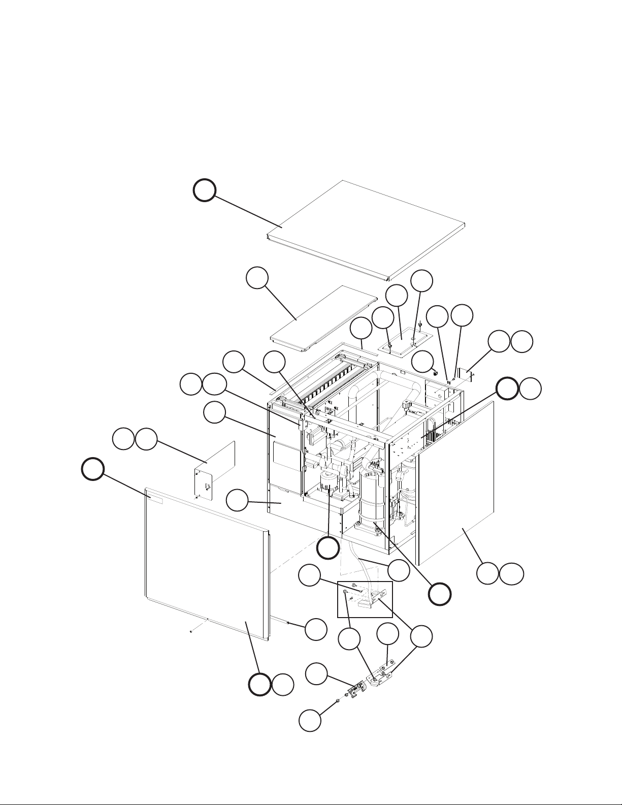
B. Refrigeration Circuit
1/2
KML-631MAH
S-0 to A-0
40
41
13a
13
2a
2
24
30
25
39
25a
23
41
22
17
41
38
41
5a55b
5c
12
12a
38
1
4a
4
41
3a
3
1a
S-0 to U-1
12
 Loading...