

Hoshizaki American, Inc. KMD-410MAH Service Manual

NO. F043-809
ISSUED: JUN. 18, 2010
REVISED:
HOSHIZAKI
MODULAR CRESCENT CUBER
MODEL
KMD-410MAH
KMD-410MWH
SERVICE MANUAL
i

CONTENTS PAGE
I. SPECIFICATIONS --------------------------------------------------------------------------------------- 1
1. SPECIFICATIONS ---------------------------------------------------------------------------------- 1
[a] KMD-410MAH (air-cooled) --------------------------------------------------------------------- 1
[b] KMD-410MWH (water-cooled) ---------------------------------------------------------------- 2
II. GENERAL INFORMATION -------------------------------------------------------------------------- 3
1. CONSTRUCTION ----------------------------------------------------------------------------------- 3
[a] KMD-410MAH ------------------------------------------------------------------------------------- 3
[b] KMD-410MWH ------------------------------------------------------------------------------------ 4
2. SEQUENCE OF OPERATION ------------------------------------------------------------------- 5
[a] ONE MINUTE FILL CYCLE ------------------------------------------------------------------- 5
[b] INITIAL HARVEST CYCLE -------------------------------------------------------------------- 5
[c] FREEZE CYCLE --------------------------------------------------------------------------------- 5
[d] DRAIN CYCLE ------------------------------------------------------------------------------------ 5
[e] NORMAL HARVEST CYCLE ----------------------------------------------------------------- 6
3. CONTROL BOARD ---------------------------------------------------------------------------------- 8
[a] CONTROL BOARD LAYOUT ----------------------------------------------------------------- 9
[b] FEATURES ---------------------------------------------------------------------------------------- 10
[c] CONTROLS AND ADJUSTMENTS ---------------------------------------------------------- 12
[d] CONTROL BOARD CHECK PROCEDURE ----------------------------------------------- 15
[e] CONTROL BOARD REPLACEMENT ------------------------------------------------------- 15
4. HARVEST CONTROL – THERMISTOR -------------------------------------------------------- 15
5. FLOAT SWITCH -------------------------------------------------------------------------------------- 16
[a] EXPLANATION OF OPERATION ------------------------------------------------------------ 16
[b] CLEANING ----------------------------------------------------------------------------------------- 16
[c] FLOAT SWITCH CHECK PROCEDURE --------------------------------------------------- 16
6. BIN CONTROL ---------------------------------------------------------------------------------------- 17
[a] EXPLANATION OF OPERATION ------------------------------------------------------------ 17
[b] BIN CONTROL CHECK PROCEDURE ----------------------------------------------------- 17
7. SWITCHES --------------------------------------------------------------------------------------------- 18
[a] CONTROL SWITCH ----------------------------------------------------------------------------- 18
[b] SERVICE SWITCH ------------------------------------------------------------------------------ 18
III. TECHNICAL INFORMATION ----------------------------------------------------------------------- 19
1. WATER CIRCUIT AND REFRIGERANT CIRCUIT ------------------------------------------- 19
2. WIRING DIAGRAM ----------------------------------------------------------------------------------- 20
3. TIMING CHART --------------------------------------------------------------------------------------- 21
4. PERFORMANCE DATA ----------------------------------------------------------------------------- 22
[a] KMD-410MAH ------------------------------------------------------------------------------------- 22
[b] KMD-410MWH ------------------------------------------------------------------------------------ 23
IV. SERVICE DIAGNOSIS ------------------------------------------------------------------------------- 24
ii

1. 10-MINUTE DIAGNOSTIC PROCEDURE ------------------------------------------------------ 24
2. DIAGNOSTIC CHARTS ----------------------------------------------------------------------------- 26
[a] NO ICE PRODUCTION ------------------------------------------------------------------------- 26
[b] EVAPORATOR IS FROZEN UP -------------------------------------------------------------- 29
[c] LOW ICE PRODUCTION ----------------------------------------------------------------------- 30
[d] ABNORMAL ICE ---------------------------------------------------------------------------------- 30
[e] OTHER ---------------------------------------------------------------------------------------------- 31
V. REMOVAL AND REPLACEMENT ----------------------------------------------------------------- 32
1. SERVICE FOR REFRIGERANT LINES --------------------------------------------------------- 32
[a] SERVICE INFORMATION ---------------------------------------------------------------------- 32
[b] REFRIGERANT RECOVERY ----------------------------------------------------------------- 33
[c] EVACUATION AND RECHARGE ------------------------------------------------------------ 33
2. BRAZING ------------------------------------------------------------------------------------------------ 34
3. COMPRESSOR ---------------------------------------------------------------------------------------- 34
4. DRIER ---------------------------------------------------------------------------------------------------- 35
5. HOT GAS VALVE ------------------------------------------------------------------------------------- 36
6. EXPANSION VALVE --------------------------------------------------------------------------------- 37
7. EVAPORATOR ---------------------------------------------------------------------------------------- 38
8. WATER REGULATING VALVE – WATER-COOLED MODEL ONLY-------------------- 39
9. ADJUSTMENT OF WATER REGULATING VALVE – WATER-COOLED
MODEL ONLY ------------------------------------------------------------------------------------------ 40
10. FAN MOTOR ------------------------------------------------------------------------------------------- 40
11. PUMP MOTOR ---------------------------------------------------------------------------------------- 41
12. WATER VALVE ---------------------------------------------------------------------------------------- 42
13. DRAIN VALVE, CLEANING VALVE -------------------------------------------------------------- 42
14. WATER TANK ----------------------------------------------------------------------------------------- 43
15. FLOAT SWITCH --------------------------------------------------------------------------------------- 44
16. BIN CONTROL SWITCH ---------------------------------------------------------------------------- 45
17. THERMISTOR ----------------------------------------------------------------------------------------- 46
18. CONTROL BOX --------------------------------------------------------------------------------------- 47
[a] CONTROL & SERVICE SWITCH------------------------------------------------------------- 48
[b] FUSE ------------------------------------------------------------------------------------------------- 48
[c] FUSE HOLDER ----------------------------------------------------------------------------------- 48
[d] CONTROL BOARD ------------------------------------------------------------------------------ 49
[e] MAGNETIC CONTACTOR --------------------------------------------------------------------- 49
[f] CONTROL BOARD TRANSFORMER ------------------------------------------------------- 49
[g] STARTER ------------------------------------------------------------------------------------------- 49
[h] RUN CAPACITOR -------------------------------------------------------------------------------- 49
[i] START CAPACITOR ----------------------------------------------------------------------------- 49
[j] CAPACITOR FOR PUMP MOTOR ----------------------------------------------------------- 50
19. SPRAY TUBE, WATER SUPPLY TUBE, SPRAY GUIDE ---------------------------------- 50
VI. CLEANING AND MAINTENANCE INSTRUCTIONS ----------------------------------------- 52
1. CLEANING ---------------------------------------------------------------------------------------------- 52
[a] CLEANING PROCEDURE --------------------------------------------------------------------- 52
[b] SANITIZING PROCEDURE -------------------------------------------------------------------- 55
2. MAINTENANCE --------------------------------------------------------------------------------------- 55
[a] STAINLESS STEEL EXTERIOR---------------------------------------------------------------56
[b] STORAGE BIN AND SCOOP ----------------------------------------------------------------- 56
[c] AIR FILTER (AIR-COOLED MODEL ONLY) ---------------------------------------------- 56
[d] CONDENSER (AIR-COOLED MODEL ONLY) ------------------------------------------- 56
3. PREPARING THE ICEMAKER FOR LONG STORAGE ------------------------------------ 56
iii
I. SPECIFICATIONS
1. SPECIFICATIONS
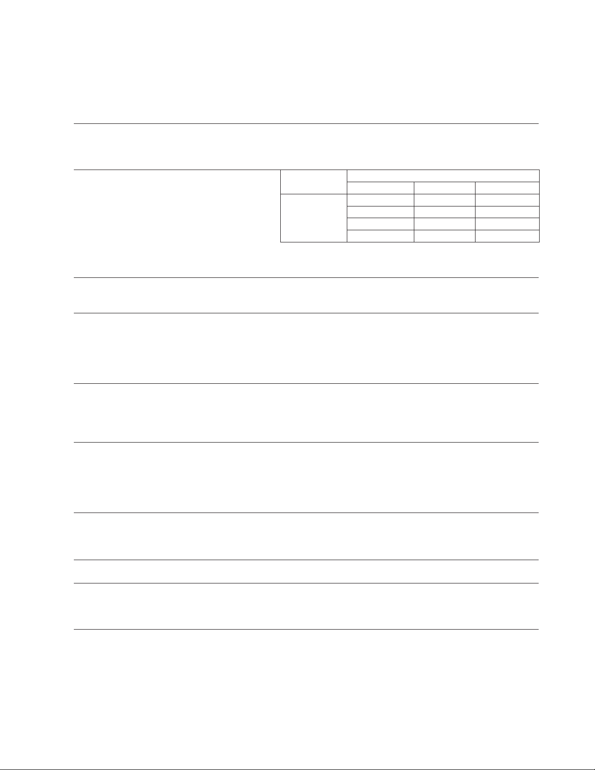
[a] KMD-410MAH (air-cooled)
AC SUPPLY VOLTAGE 115/60/1 㩷
AMPERAGE 8.0 A (5 Min. Freeze AT 104°F / WT 80°F)
MINIMUM CIRCUIT AMPACITY 15 A
MAXIMUM FUSE SIZE 15 A
APPROXIMATE ICE PRODUCTION Ambient WATER TEMP. (°F)
PER 24 HR. Temp.(°F) 50 70 90
lbs./day (kg/day) 70 *415 (188) 388 (176) 354 (160)
Reference without *marks 80 395 (179) 353 (160) 320 (145)
90 388 (176) *324 (147) 289 (131)
100 382 (173) 316 (143) 257 (117)
SHAPE OF ICE Crescent Cube
ICE PRODUCTION PER CYCLE 8.5 lbs. (3.9 kg) 416 pcs.
APPROXIMATE STORAGE CAPACITY N/A
ELECTRIC & WATER CONSUMPTION 90/70°F 70/50°F
ELECTRIC W (kWH/100 lbs.) 780(5.8) 710(4.1)
WATER gal./24HR (gal./100 lbs.) 73(22.6) 148(35.7)
EXTERIOR DIMENSIONS (WxDxH) 22-1/4" x 24-1/8" x 24" (565 x 613 x 610 mm)
EXTERIOR FINISH Stainless Steel, Galvanized Steel (Rear)
WEIGHT Net 126 lbs. (57 kg), Shipping 161 lbs. (73 kg)
CONNECTIONS - ELECTRIC Permanent - Connection
- WATER SUPPLY Inlet 1/2" FPT
- DRAIN Outlet 3/4" FPT
CUBE CONTROL SYSTEM Float Switch
HARVESTING CONTROL SYSTEM Hot Gas and Water, Thermistor and Timer
ICE MAKING WATER CONTROL Timer Controlled, Overflow Pipe
COOLING WATER CONTROL N/A
BIN CONTROL SYSTEM Mechanical Level Switch with Delay
COMPRESSOR Hermetic, Model NT6217GKV
CONDENSER Air-Cooled, Fin and tube type
EVAPORATOR Vertical type, Stainless Steel and Copper
REFRIGERANT CONTROL Thermostatic Expansion Valve
REFRIGERANT CHARGE R-404A, 1 lb. 2.3 oz. (520g)
DESIGN PRESSURE High 467PSIG, Low 206PSIG
P.C. BOARD CIRCUIT PROTECTION High Voltage Cut-out (Internal)
COMPRESSOR PROTECTION Auto-reset Overload Protector (Internal)
REFRIGERANT CIRCUIT PROTECTION Auto-reset High Pressure Control Switch
LOW WATER PROTECTION Float Switch
ACCESSORIES - SUPPLIED N/A
- REQUIRED Ice Dispenser or Ice Storage Bin
OPERATING CONDITIONS VOLTAGE RANGE 104 - 127 V
AMBIENT TEMP. 45 -100° F
WATER SUPPLY TEMP. 45 - 90° F
WATER SUPPLY PRESSURE 10 - 113PSIG
We reserve the right to make changes in specifications and design without prior notice.
1
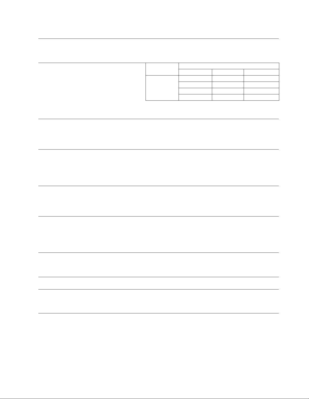
[b] KMD-410MWH (water-cooled)
AC SUPPLY VOLTAGE 115/60/1 㩷
AMPERAGE 6.5 A (5 Min. Freeze AT 104°F / WT 80°F)
MINIMUM CIRCUIT AMPACITY 15 A
MAXIMUM FUSE SIZE 15 A
APPROXIMATE ICE PRODUCTION Ambient WATER TEMP. (°F)
PER 24 HR. Temp.(°F) 50 70 90
lbs./day (kg/day) 70 *440 (200) 423 (192) 392 (178)
Reference without *marks 80 427 (194) 401 (182) 364 (165)
90 423 (192) *382 (173) 347 (157)
100 414 (188) 373 (169) 315 (143)
SHAPE OF ICE Crescent Cube
ICE PRODUCTION PER CYCLE 8.2 lbs. (3.7 kg) 416 pcs.
APPROXIMATE STORAGE CAPACITY N/A
ELECTRIC & WATER CONSUMPTION 90/70°F 70/50°F
ELECTRIC W (kWH/100 lbs.) 680(4.3) 670(3.7)
WATER gal./24HR (gal./100 lbs.) 89(23.2) 120(27.2)
WATER COOLED CONDENSER 552(145) 267(61)
gal./24HR (gal./100 lbs.) 㩷 㩷
EXTERIOR DIMENSIONS (WxDxH) 22-1/4" x 24-1/8" x 24" (565 x 613 x 610 mm)
EXTERIOR FINISH Stainless Steel, Galvanized Steel (Rear)
WEIGHT Net 128 lbs. (58 kg), Shipping 163 lbs. (74 kg)
CONNECTIONS - ELECTRIC Permanent - Connection
- WATER SUPPLY Inlet 1/2" FPT Cond. Inlet 1/2" FPT
- DRAIN Outlet 3/4" FPT Cond. Outlet 1/2" FPT
CUBE CONTROL SYSTEM Float Switch
HARVESTING CONTROL SYSTEM Hot Gas and Water, Thermistor and Timer
ICE MAKING WATER CONTROL Timer Controlled, Overflow Pipe
COOLING WATER CONTROL N/A
BIN CONTROL SYSTEM Mechanical Level Switch with Delay
COMPRESSOR Hermetic, Model NT6217GKV
CONDENSER Water-Cooled, Tube in tube type
EVAPORATOR Vertical type, Stainless Steel and Copper
REFRIGERANT CONTROL Thermostatic Expansion Valve
REFRIGERANT CHARGE R-404A, 14.1 oz. (400g)
DESIGN PRESSURE High 427PSIG, Low 206PSIG
P.C. BOARD CIRCUIT PROTECTION High Voltage Cut-out (Internal)
COMPRESSOR PROTECTION Auto-reset Overload Protector (Internal)
REFRIGERANT CIRCUIT PROTECTION Auto-reset High Pressure Control Switch
LOW WATER PROTECTION Float Switch
ACCESSORIES - SUPPLIED N/A
- REQUIRED Ice Dispenser or Ice Storage Bin
OPERATING CONDITIONS VOLTAGE RANGE 104 - 127 V
AMBIENT TEMP. 45 -100° F
WATER SUPPLY TEMP. 45 - 90° F
WATER SUPPLY PRESSURE 10 - 113 PSIG
We reserve the right to make changes in specifications and design without prior notice.
2
II. GENERAL INFORMATION
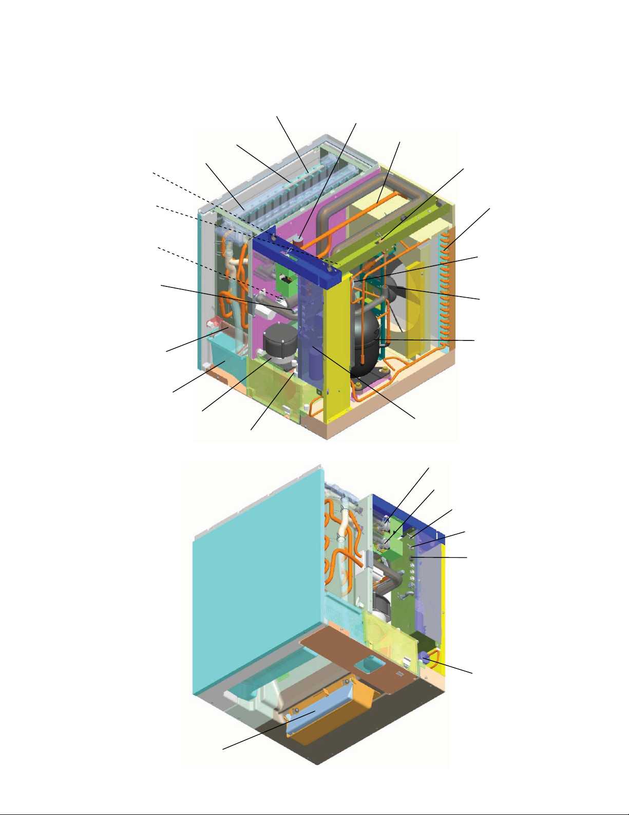
1. CONSTRUCTION
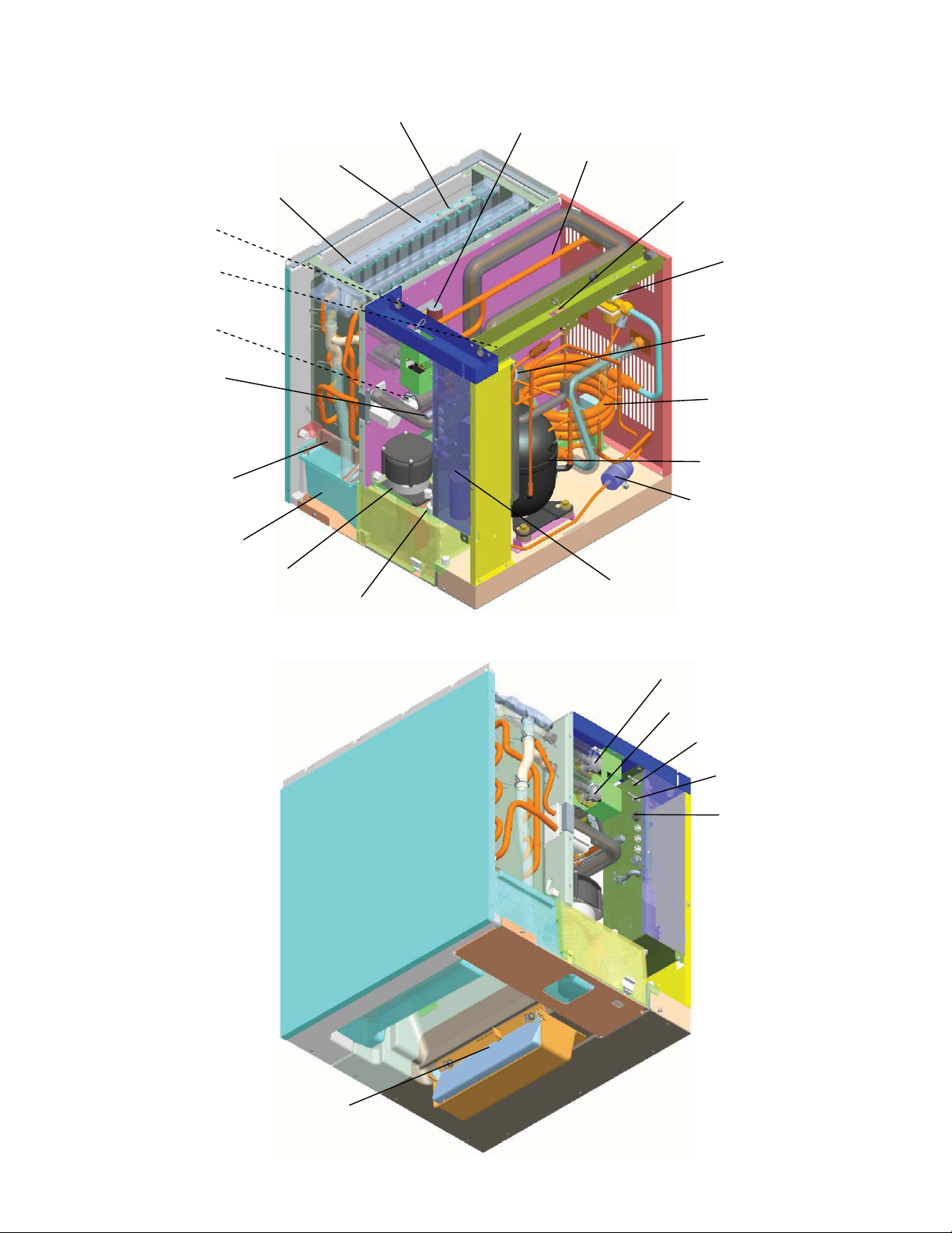
[a] KMD-410MAH
Cleaning
Valve
Access Valve
(High Side)
Thermistor
Access Valve
(Low Side)
Cube Guide
Water Tank
Spray Tube
Pump Motor
Water Supply Tube
Spray Guide
Float Switch
Drain Valve
Water Supply Inlet
Hot Gas Valve
Condenser
Expansion Valve
Fan Motor
Compressor
Control Box
Harvest Water Valve
Fill Water Valve
Control Switch
Service Switch
Fuse Holder (Fuse)
Drier
Bin Control Switch
3
[b] KMD-410MWH
Cleaning Valve
Access Valve
(High Side)
Thermistor
Access Valve
(Low Side)
Cube Guide
Water Tank
Spray Tube
Pump Motor
Spray Guide
Float Switch
Water Supply Tube
Drain Valve
Water Supply Inlet
Hot Gas Valve
Water Regulator
Expansion Valve
Condenser
Compressor
Drier
Control Box
Harvest Water Valve
Fill Water Valve
Control Switch
Service Switch
Fuse Holder (Fuse)
Bin Control Switch
4

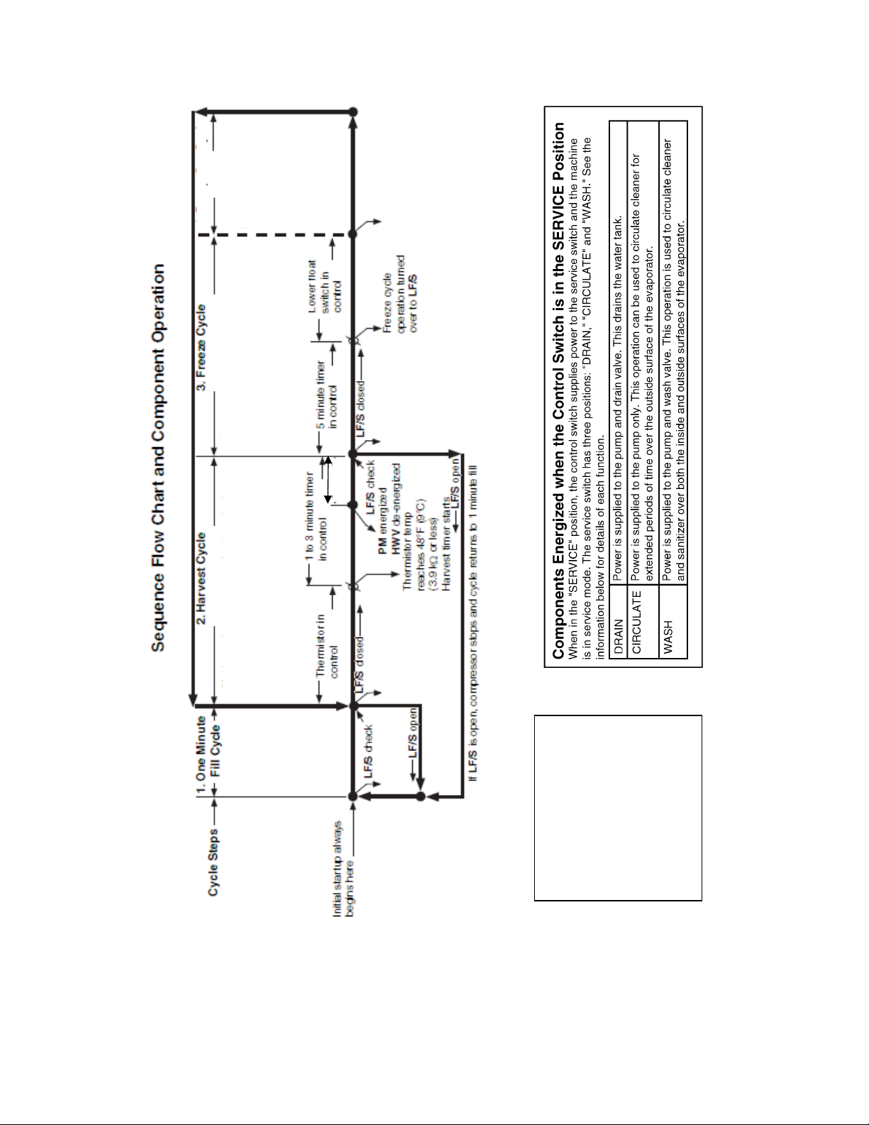
2. SEQUENCE OF OPERATION
The steps in the sequence are as outlined below. When power is supplied, a 5 second delay
occurs at startup. Note that the order of the LEDs from the outer edge of the board is 5, 6, 8,
9, 4, 7.
[a] ONE MINUTE FILL CYCLE
LED 8 is on. HWV opens and the fill period begins. After 1 minute, the board checks for a
closed LF/S. If LF/S is closed, the harvest cycle begins. If not, HWV will remain energized
through additional 1 minute cycles until water enters the sump and LF/S closes. This serves
as a low water safety to protect the water pump.
[b] INITIAL HARVEST CYCLE
LEDs 5, 6, and 8 are on. HWV remains open, Comp energizes, HGV opens, and harvest
begins. As the evaporator warms, the thermistor located on the suction line checks for a 9°C
temperature. When 9°C is reached, a 3.9 k signal turns the harvest over to the adjustable
harvest timer which is factory set for normal conditions. The timer has settings of 60, 90, 120,
and 180 seconds (S1 dip switch 1 & 2). When the harvest timer completes its count down,
the harvest cycle is complete and the freeze cycle starts.
The minimum total time allowed by the board for a complete harvest cycle is 2 minutes.
HWV is open during harvest for a maximum of 6 minutes or the length of harvest minus 0,
10, 30, or 50 seconds (adjustable by S1 dip switch 7 & 8), whichever is shorter. LED 8 goes
off when HWV closes. PM energizes and runs for the last 0, 10, 30, or 50 seconds of harvest
depending on S1 dip switch 7 & 8 setting. LED 7 comes on when PM energizes. At the end
of harvest, the control board checks the position of LF/S and proceeds to the freeze cycle if
it is closed or calls for a 1-minute fill if it is open.
[c] FREEZE CYCLE
LEDs 5 & 7 are on. Comp continues to run, PM and FMS energize, HGV closes and the
freeze cycle starts. For the first 5 minutes after the thermistor temperature reaches 2°C, the
control board will not accept a signal from LF/S and UF/S. This minimum freeze period acts
as a short cycle protection. At the end of this period, LF/S and UF/S assumes control. As ice
builds on the evaporator the water level in the sump lowers and LF/S opens, FWV opens
(LED 9 is on when FWV is open). The refill will last until UF/S closes or for 60 seconds,
whichever is shorter. After UF/S closes, FWV closes 3 seconds later. KMD-410 refills 1 time.
After the refill, the freeze continues until LF/S opens again and terminates ice production.
[d] DRAIN CYCLE
LEDs 4, 5, 6, and 7 are on. Comp continues to run, HGV opens, FMS de-energizes. PM
stops for 2 seconds, DV energizes, then restarts to take water from the sump and force it
through DV and down the drain. When the drain timer stops counting, the drain is complete.
The drain timer is 10 or 20 seconds (S1 dip switch 3 & 4). Drain cycle always occurs on the
2nd harvest after startup. Then, depending on the control board setting, drain cycle occurs
every cycle, or every 2nd, 5th, or 10th cycles (S1 dip switch 5 & 6).
5

[e] NORMAL HARVEST CYCLE
LEDs 5, 6, and 8 are on. Comp continues to run, HGV remains open and HWV opens. As
the evaporator warms, the thermistor reaches 9ºC. The control board then receives the
thermistor’s 3.9k signal and starts the harvest timer. HWV is open during harvest for a
maximum of 6 minutes or the length harvest minus 0, 10, 30, or 50 seconds (adjustable by
S1 dip switch 7 & 8), whichever is shorter. LED 8 goes off when HWV closes. PM energizes
and runs for the last 0, 10, 30, or 50 seconds of harvest depending on S1 dip switch 7 & 8
setting. LED 7 comes on when PM energizes. At the end of harvest, the control board
checks for the position of LF/S and proceeds to the freeze cycle if it is closed or calls for a
1-minute fill if it is open.
The unit continues to cycle through [c], [d], and [e] sequence until the bin control is activated
and shuts the unit down. When the bin control is activated, the “POWER OK” LED flashes.
Note: To prevent incomplete batches of ice from foaming on the evaporator, the control
board will only shut down the machine within the first 5 minutes of the freeze cycle
after the thermistor temperature reaches 2 ºC. If ice pushes the bin control actuator in
(open) after this minimum freeze period, the control board will allow the machine to
complete the freeze cycle and the following harvest cycle before shutting down the
machine.
Legend: Comp–compressor; DV–drain valve; FMS–self-contained fan motor; FWV–fill
water valve; HGV–hot gas valve; HWV–harvest water valve; LF/S–lower float
switch contacts; UF/S–upper float switch contacts; PM–pump motor
6
cycle (S1 dip
th
4. Drain Cycle
Factory set for every
10
Switch 5 & 6)
Pump motor stops
for 2 sec. and then
runs for 10/20 sec.
(S1 dip switch 3 & 4)
PM de-energizes 0/2 sec.,
energizes for 10/20
sec.
COMP continues
DV energized/
HGV energized
FMS de-energized
xMinimum freeze time: 5 minutes
xMaximum freeze time: freeze time setting
xLower float switch used to initiate water
Tank refill (1 refill for KMD-410)
xUpper float switch used to terminate
water tank refill (1 minute maximum fill
time)
COMP continues
PM continues
FWV energized/
de-energized
for refill only
FMS energized
HGV de-energized
0, 0,30,
or 50 sec
xMaximum harvest water valve time: 6 minutes
(HWV time is 6 minutes of the length of harvest
minus 0, 10, 30, or 50 sec. (S1 dip switch
7 & 8), whichever is shorter. PM energizes
and runs for the last 0, 10, 30, or 50 sec. of
harvest.)
xMaximum harvest time: 20 minutes
COMP energized
HGV energized
HWV continues
FWV de-energized
DV de-energized
KMD-410MAH, 410MWH
HWV energized
5 second delay
“H” board will have
Legend:
COMP - compressor
DV – drain valve
FMS – self-contained fan motor
FWV – fill water valve
HGV – hot gas valve
HWV – harvest water valve
LF/S – lower float switch contacts
PM – pump motor
UF/S – upper float switch contacts
7
3. CONTROL BOARD
* A HOSHIZAKI exclusive solid-state control is employed in KMD-410MAH and
KMD-410MWH Crescent Cubers.
* All models are pretested and factory-adjusted.
1. Fragile, handle very carefully.
2. A control board contains integrated circuits, which are susceptible to failure
due to static discharge. It is especially important to touch the metal part of the
unit when handling or replacing the board.
3. Do not touch the electronic devices on the board or the back of the board to
prevent damage to the board.
4. Do not change wiring and connections.
5. Always replace the whole board assembly if it goes bad.
6. Do not short out power supply to test for voltage.ᴾ
8
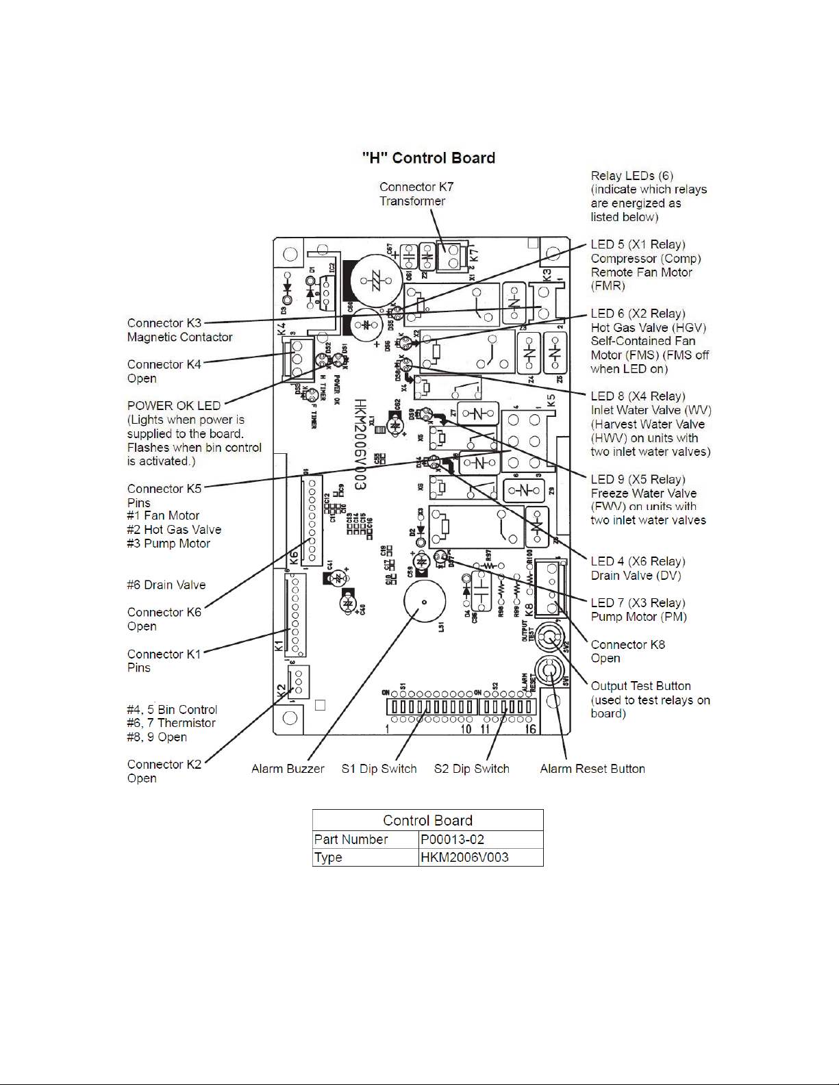
[a] CONTROL BOARD LAYOUT
#4 Harvest Water Valve
#5 Freeze Water Valve
#1, 2, 3 Float Switch
9

[b] FEATURES
a) Maximum Water Supply Period - 6 minutes
The harvest water valve will be open during harvest for 6 minutes or the length of harvest
minus 0, 10, 30, or 50 seconds (adjustable by S dip switch 7 & 8), whichever is shorter.
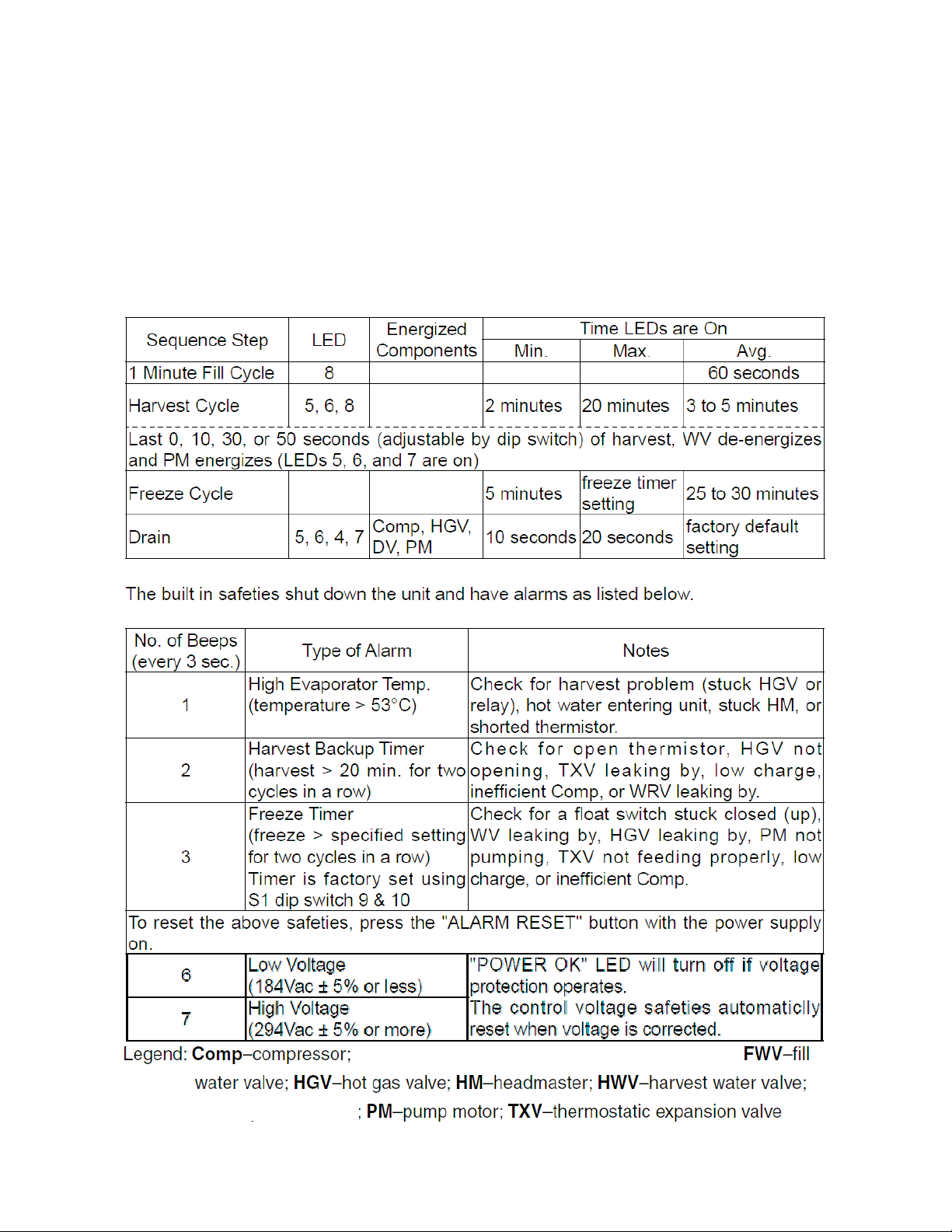
b) Harvest Backup Timer and Freeze Timer
The harvest backup timer shuts down the icemaker if, for two cycles in a row, the harvest
cycle takes more than 20 minutes to complete. The control board will signal this problem
using 2 beeps every 3 seconds.
The freeze timer shuts down the icemaker if, for two cycles in a row, the freeze cycle takes
longer than the time specified to complete. The control board will signal this problem using 3
beeps every 3 seconds. The time is factory set using S1 dip switch 9 & 10.
The alarm reset button on the control board must be pressed with power on to reset either of
these safeties.
c) High Temperature Safety
The temperature of the suction line in the refrigeration circuit is limited by the high
temperature safety. This protects the unit from excessively high temperatures. If the
evaporator temperature rises above 53°C ± 4°C, the thermistor operates the safety.
This shuts down the circuit and the icemaker automatically stops.
The control board will signal this problem using 1 beep every 3 seconds. The alarm reset
button on the control board must be pressed with power on to reset the safety.
d) Low Water Safety
The control board checks the position of the lower float switch at the end of the initial one
minute water fill cycle and at the end of each harvest cycle.
If the lower float switch is in the up position (electrical circuit closed), the control board
changes to the next cycle. If the lower float switch is in the down position (electrical circuit
open), the control board changes to additional one minute water fill cycles until water enters
the sump and the float switch closes. When the float switch closes, the control board
changes to the next cycle. The unit will not start without adequate water in the sump. This
serves as a low water safety to protect the water pump.
For water-cooled model, if the condenser water supply is shut off, the unit is protected by the
high-pressure switch.
e) High Voltage and Low Voltage Cut-outs
The maximum and minimum allowable supply voltages of this icemaker are limited by the
high voltage and low voltage cut-outs.
If miswiring (especially on single 3 phase wire models) causes excessive voltage ( 294 Vac
± 5% or more) on the control board, the high voltage cut-out shuts down the circuit in 3
seconds and the icemaker automatically stops. The control board will signal this problem
using 7 beeps every 3 seconds.
The icemaker also automatically stops in cases of insufficient voltage (184Vac ± 5% or less).
The control board will signal this problem using 6 beeps every 3 seconds.
When the proper supply voltage is resumed, the icemaker automatically starts running
again.
10
f) LED Lights and Audible Alarm Safeties
The control board includes LED indicator lights, audible alarm safeties, and an output test
feature. The "POWER OK" LED indicates control voltage and will remain on unless a control
voltage problem occurs. The “POWER OK” LED flashes continuously when the bin is full
and DV energizes for a maximum of 5 minutes to drain the water tank.
At startup, a 5 second delay occurs to stabilize the circuit. LEDs 4 through 8 energize and
sequence from initial startup as listed in the table below. Note that the order of the LEDs
from the outer edge of the board is 5, 6, 8, 9, 4, 7. For more information, see "2.
SEQUENCE OF OPERATION".
5, 7 (and
9 at refill)
HWV
HWV, HGV,
Comp
Comp, PM, FMS
(FWV at refill)
DV- drain valve; FMS-self-contained fan motor;
WRV-water regulating valve;
11
[c] CONTROLS AND ADJUSTMENTS
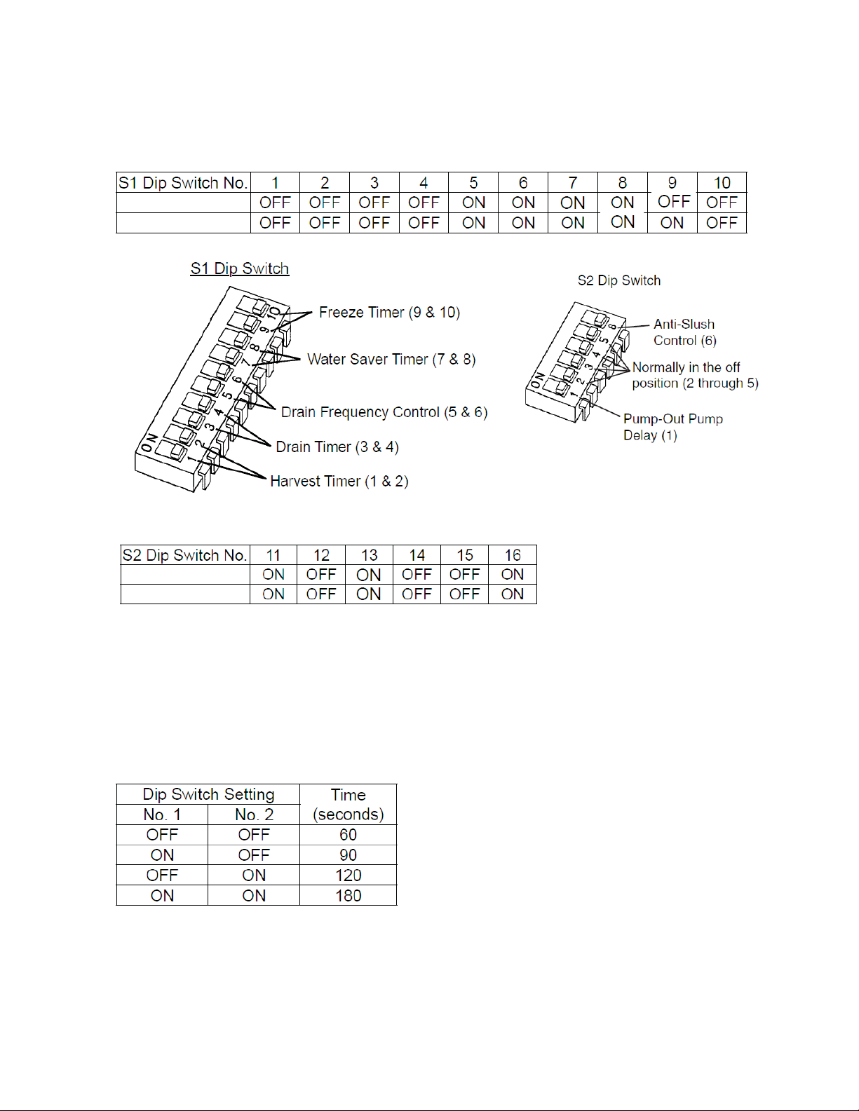
a) Default Dip Switch Settings
The dip switch is factory-adjusted to the following positions:
KMD-410MAH
KMD-410MWH
KMD-410MAH
KMD-410MWH
Do not adjust the S2 dip switch. These must be left in the factory default position, or the unit
will not operate properly.
b) Harvest Timer (S1 dip switch 1 & 2)
Used for adjustment of the harvest timer. The harvest timer starts counting when the
thermistor reads a certain temperature at the evaporator outlet.
12
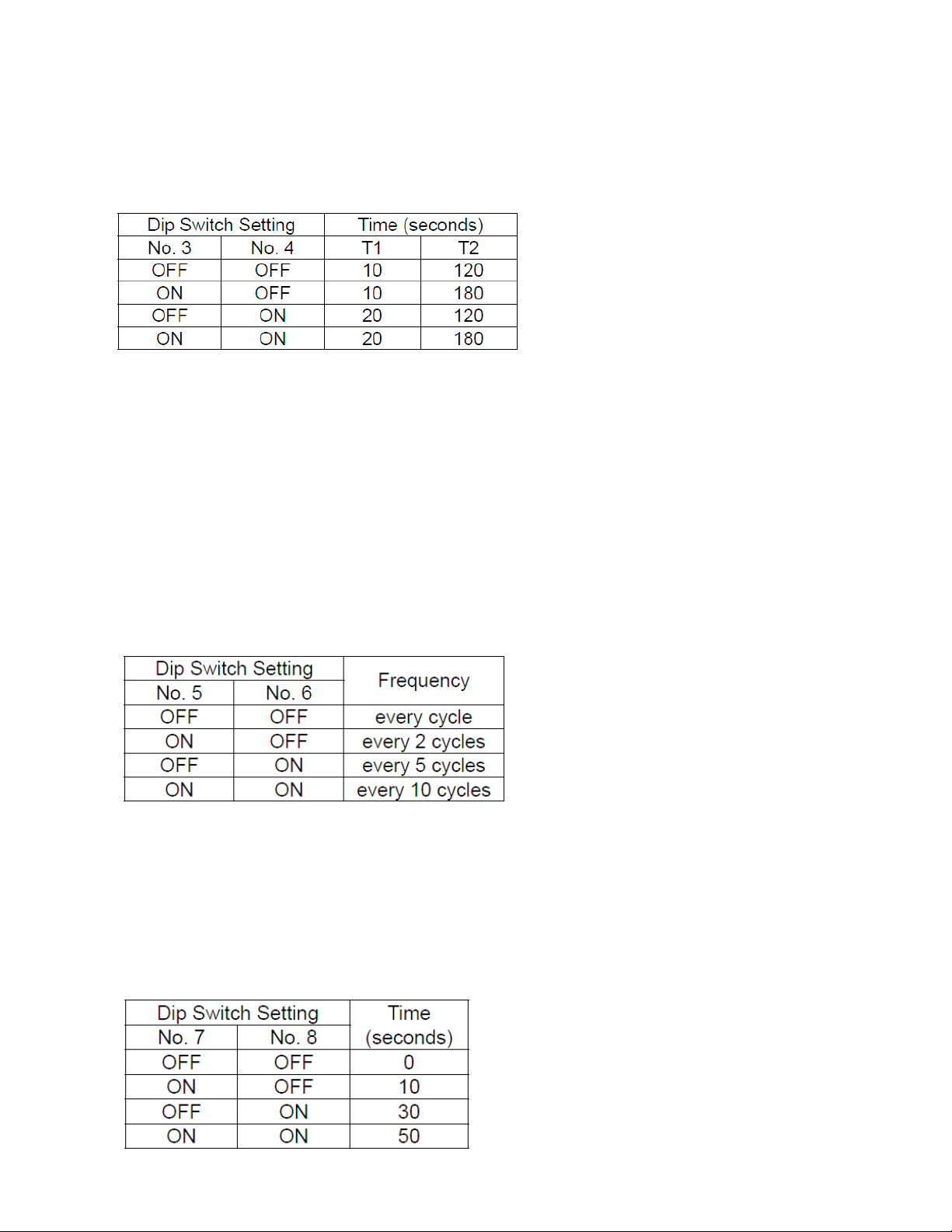
c) Drain Timer (S1 dip switch 3 & 4)
Once every ten freeze cycles, the drain valve opens to drain the water tank for the time
determined by the drain timer. These switches also determine the time to delay completion
of a defrost cycle, i.e. the minimum defrost time.
Do not change this setting, or the unit will not operate properly or produce high quality ice.
T1: Time to drain the water tank
T2: Harvest timer at drain
Drain cycle always occurs on the 2nd harvest after startup. Then, depending on the drain
frequency control setting (dip switch 5 & 6), drain cycle occurs every cycle, or every 2nd, 5th,
or 10th cycle.
d) Drain Frequency Control (S1 dip switch 5 & 6)
The water tank drains at the frequency set by the drain frequency control.
The drain frequency control is factory-adjusted to drain the water tank every 10 cycles, and
no adjustment is required. However, where water quality is bad and the icemaker needs a
drain more often, the drain frequency can be adjusted as shown in the table below.
e) Water Saver Timer (S1 dip switch 7 & 8)
The water saver timer allows the water valve to close and the pump motor to circulate water
in the tank during the final part of harvest. The water valve is open during harvest for a
maximum of 6 minutes or the length of harvest minus 0, 10, 30, or 50 seconds (determined
by the water saver timer setting), whichever is shorter. When the water valve closes, the
pump motor energizes and runs for the time determined by the water saver timer setting.
The water saver timer is factory-adjusted, and no adjustment is required.
13
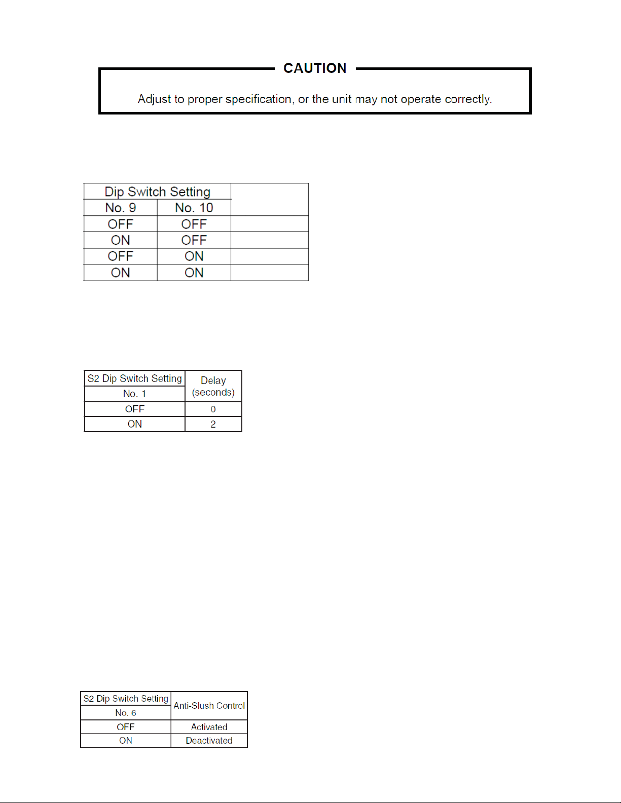
f) Freeze Timer (S1 dip switch 9 & 10)
The freeze timer setting determines the maximum allowed freeze time to prevent possible
freeze-up issues. Upon termination of freeze timer, machine initiates the harvest cycle. After
2 consecutive timer terminations, machine will shut down, possibly indicating a problem.
The freeze timer is factory adjusted, and no adjustment is required.
Time(50/60Hz)
(minutes)
60/60
60/50
100/70
120/100
g) Pump-Out Pump Motor Delay (S2 dip switch 1)
The pump-out pump motor delay determines whether or not the pump motor de-energizes
for 2 seconds before restarting at the beginning of a drain cycle.
The pump-out pump motor delay is factory adjusted and no adjustment is required.
h) Refill Counter (S2 dip switch 2, 3, & 4)
Do not adjust. These must be left in the factory default position or the unit will not operate
properly. The KMD-410MAH and KMD-410MWH refill 1 time.
i) Factory Use (S2 dip switch 5)
Must remain off.
j) Anti-Slush Control (S2 dip switch 6)
The anti-slush control helps prevent slushing during the freeze cycle on small icemakers.
It is deactivated on the KMD-410 series.
When activated, the thermistor located on the suction line checks for a 34 ºF (1 ºC)
temperature as the evaporator cools. When 34 ºF (1 ºC) is reached, a 5.9 k signal causes
the control board to de-energize the pump motor for 10 seconds.
Do not adjust. This must be left in the factory default position or the unit will not operate
properly.
14
[d] CONTROL BOARD CHECK PROCEDURE
Before replacing a control board that does not show a visible defect and that you suspect is
bad, always conduct the following check procedure. This procedure will help you verify your
diagnosis.
1) Check the dip switch settings to assure that S1 dip switch 3, 4, 7, 8, 9, & 10 and S2 dip
switch 1 through 6 are in the factory default position. S1 dip switch 1, 2, 5, & 6 are
cleaning adjustments and the settings are flexible.
2) Move the control switch to the "ICE" position and check for proper control voltage. If the
"POWER OK" LED is on, the control voltage is good. If the "POWER OK" LED is off,
check the control transformer circuit. If no voltage is present, check the power supply
circuit.
3) The output test button provides a relay sequence test. Make sure the control switch is in
the "ICE" position, then press the "OUTPUT TEST" button. The correct lighting sequence
should be 5, 6, 7, 8, 9, 4. Some components (e.g., the compressor) will cycle during the
test. Each LED flashes three times in 5 seconds. LED 5 continues to flash while LED 6
flashes. Following the output test sequence, the icemaker will resume normal operation
beginning with the 1 minute fill cycle.
[e] CONTROL BOARD REPLACEMENT
The dip switches should be adjusted to the factory default settings as outlined in this manual.
S2 dip switch 5 must remain off.
4. HARVEST CONTROL – THERMISTOR
A thermistor (semiconductor) is used as a harvest control sensor and anti-slush sensor.
The resistance varies depending on the suction line temperatures. The thermistor detects
the temperature of the evaporator outlet to start the harvest timer or momentarily stop the
pump motor during the freeze cycle. No adjustment is required. If necessary, check for
resistance between thermistor leads, and visually check the thermistor mounting, located on
the suction line next to the evaporator outlet.
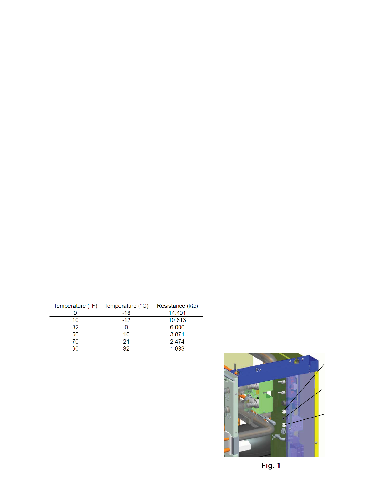
Check a thermistor for resistance by using the following
procedure:
1) Disconnect the thermistor (orange wires) at the
2-pin connector on the control box. See Fig. 1.
2) Remove the thermistor. See "V. 17. THERMISTOR."
3) Immerse the thermistor sensor portion in a glass
containing ice and water for 2 or 3 minutes.
4) Check for a resistance between thermistor leads.
Thermistor
Connector
(orange wires)
Bin Control
Wires
(black)
Float Switch
Connector
(red wires)
Normal reading is within 3.5 to 7 k.
Replace the thermistor if it exceeds the
normal reading.
15
 Loading...