

Hoshizaki America, Inc.
Hoshizaki
Modular Crescent Cuber
Models
KM-650MAH
“A Superior Degree
of Reliability”
www.hoshizaki.com
KM-650MWH
KM-650MRH
PARTS LIST
™
Number: 71264
Issued: 11-28-2006
Revised: 2-1-2011

CONTENTS
Auxiliary Codes ...................................................................................................................... 3
Note About Ordering Parts .................................................................................................... 3
Material Abbreviations ........................................................................................................... 4
A. Ice Cuber Assembly .......................................................................................................... 5
KM-650MAH ...................................................................................................................... 5
KM-650MWH ..................................................................................................................... 8
KM-650MRH ....................................................................................................................11
B. Refrigeration Circuit ......................................................................................................... 14
KM-650MAH .................................................................................................................... 14
KM-650MWH ................................................................................................................... 20
KM-650MRH ................................................................................................................... 26
C. Water Circuit .................................................................................................................... 32
D. Control Box Assembly ...................................................................................................... 35
KM-650MAH .................................................................................................................... 35
KM-650MWH, KM-650MRH ............................................................................................ 38
E. Label Location ................................................................................................................. 41
KM-650MAH .................................................................................................................... 41
KM-650MWH ................................................................................................................... 43
KM-650MRH ................................................................................................................... 45
F. Top Panel Assembly ......................................................................................................... 47
G. Front Panel Assembly ..................................................................................................... 48
KM-650MAH .................................................................................................................... 48
KM-650MWH, KM-650MRH ............................................................................................ 49
H. Pump Motor Assembly..................................................................................................... 50
J. Accessories & Packaging ................................................................................................. 51
2

Auxiliary Codes
KM-650MAH
R-0 July 2006
S-1 January 2007
S-2 May 2007
T-0 January 2008
U-0 January 2009
U-1 February 2009
V-0 February 2010
V-1 March 2010
V-2 May 2010
V-3 June 2010
V-4 August 2010
KM-650MWH
R-0 July 2006
S-1 January 2007
T-0 January 2008
U-1 June 2009
V-0 January 2010
V-1 March 2010
V-2 May 2010
V-3 June 2010
V-4 August 2010
KM-650MRH
R-0 July 2006
S-1 January 2007
T-0 January 2008
U-0 January 2009
U-1 February 2009
U-2 July 2009
V-0 January 2010
V-1 March 2010
V-2 May 2010
V-3 June 2010
V-4 August 2010
Auxiliary Code Breakdown
The auxiliary code is the rst two characters in the serial number. The rst character
indicates the year. Years progress or regress in alphabetical order. The series runs from
"A" through "V" and the letters "I" and "O" are skipped. The second character indicates
signicant part changes within a year. Base is "0" and this number advances for each
change. In cases where there is a letter in parentheses, this designates the month. This
is the last character in the serial number. The series runs from "(A)" through "(M)" and the
letter "(I)" is skipped. This designation is only included when identifying a parts change
within an auxiliary code.
Note About Ordering Parts
Most assemblies cannot be ordered as complete units; parts in the assemblies generally
must be ordered separately.
3

Material Abbreviations
ALUMINUM
AL = Aluminum
COPPER
CU = Copper
PLASTIC
ABS = Acrylonitrile -butadiene - styrene
AC = Polyacetal
EVA = Ethylene vinyl acetate
PA = Polyamide = Nylon
PC = Polycarbonate
PE = Polyethylene
PES = Polyester
PETP = Polyethylene terephthalate = Tetlon
PP = Polypropylene
PS = Polystyrene
PTFE = Polytetrauoroethylene = Teon
PUR = Polyurethane
PVC = Polyvinyl chloride
RUBBER
VN = Vinyl Nitrile
EPDM = EP rubber
NBR = Nitrile butadiene rubber
NR = Natural rubber
NP = Neoprene
SI.R = Silicone rubber
SY.R = Synthetic rubber
EPH = Epichlorohydrin
STEEL
GS = Galvanized steel
SS = Stainless steel
PS = Plated steel
PAS = Primed steel
4
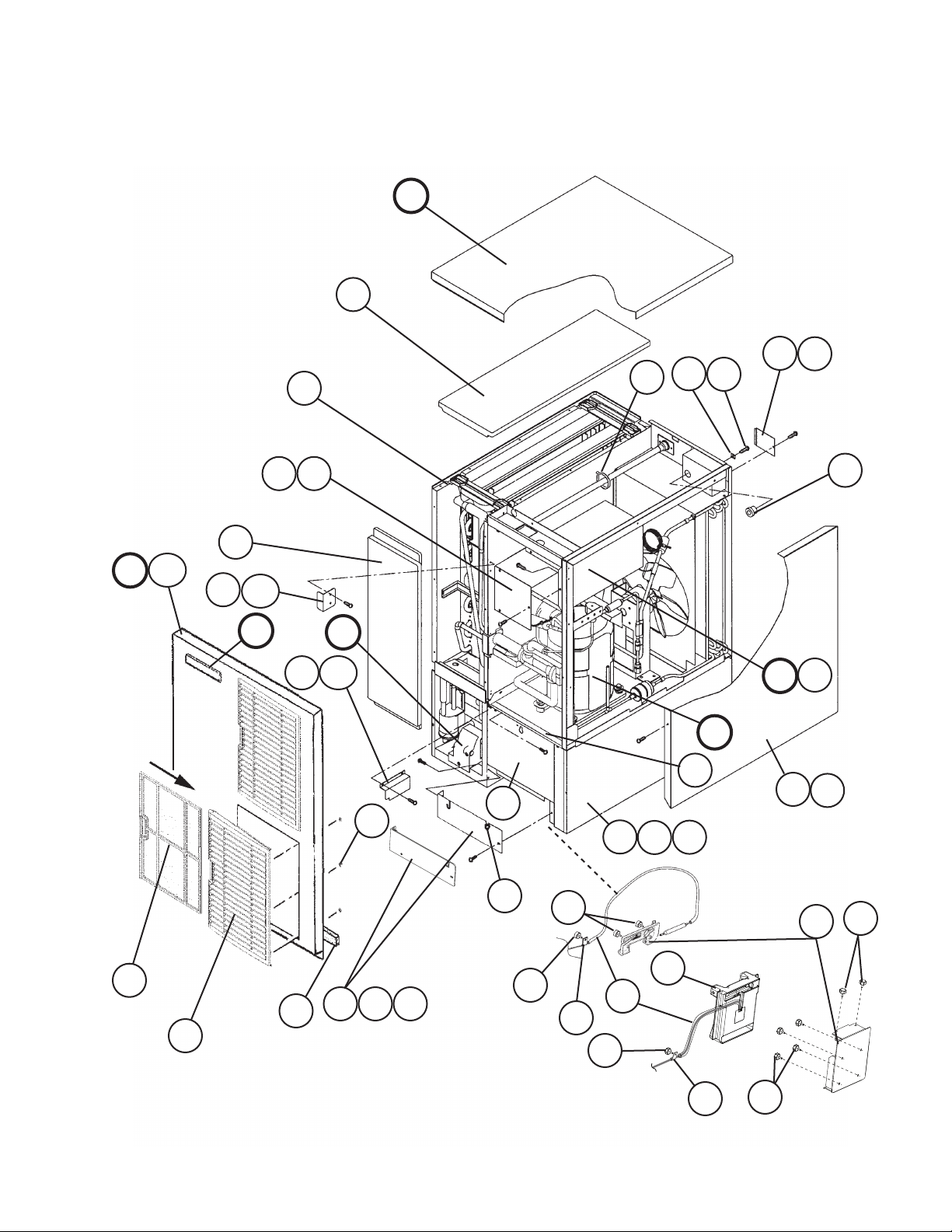
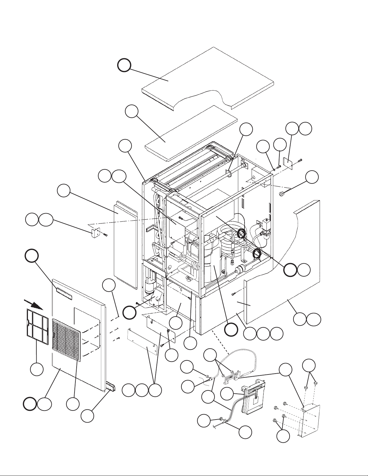
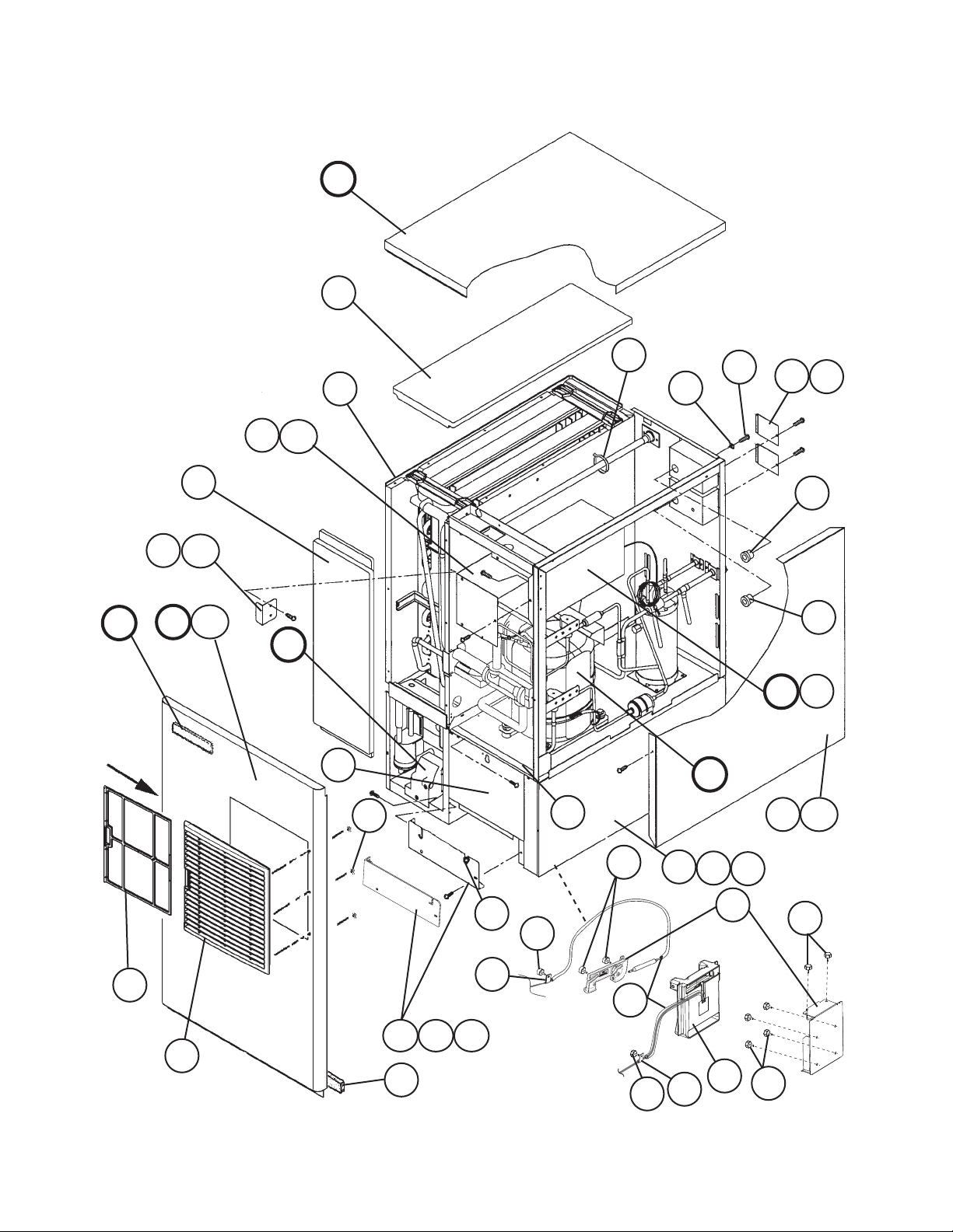
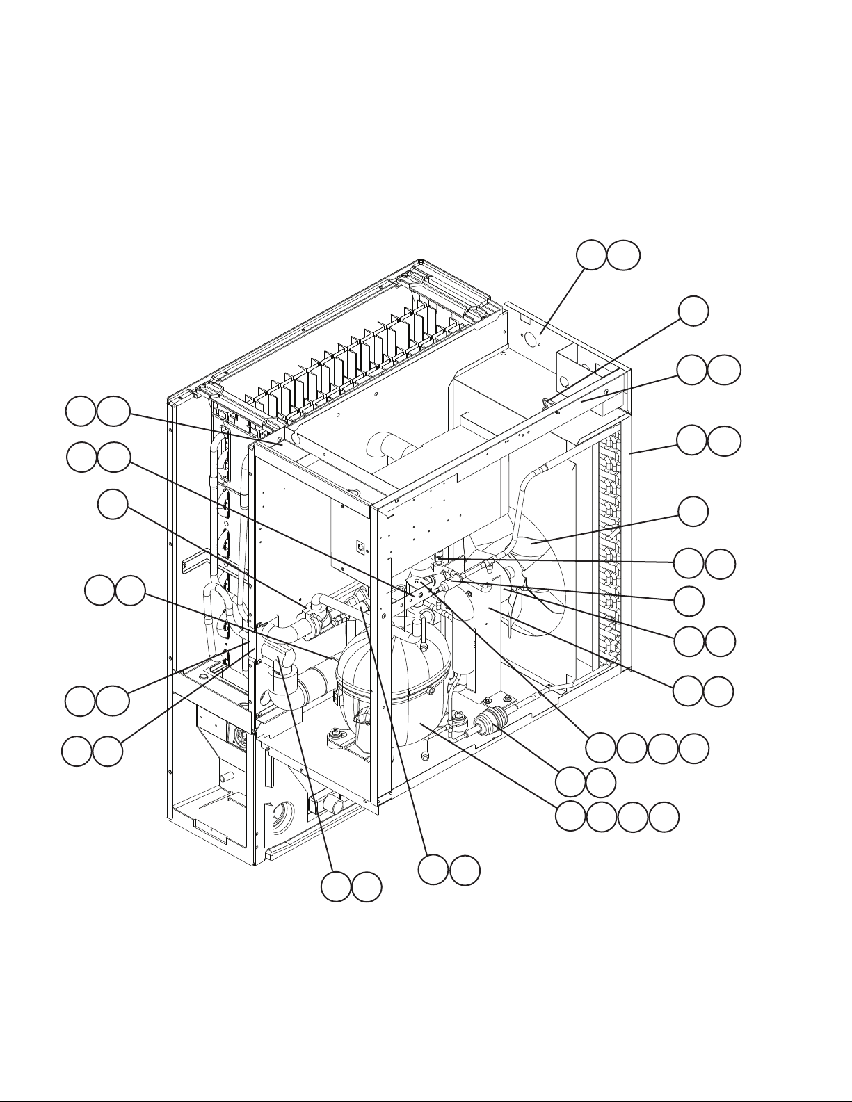
A. Ice Cuber Assembly
KM-650MAH
R-0 to V-4
1
11
F
21
6a
6
4
5
G
18
G1
17
24
10
24a
E
9a
9
20
C
22a
22
D
D1
B
16
8
15
S-2 (E), U-1 & later
8a
26
23
3
19
U-1 (M) and Later
R-0 to U-1 (L)
3a 3b
7
27
26
14
13
26
2
12
2a
28
For thermostat, see
"D. Control Box Assembly"
R-0, S-1, S-2 (L) to U-0
25
13
5
26
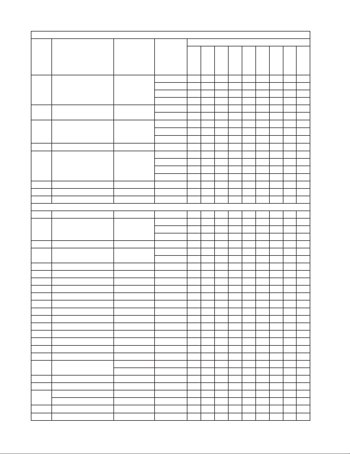
Title: A. Ice Cuber Assembly Model: KM-650MAH
Required Number
S-2
(L)
Index
No. Description
B Refrigeration Circuit - 1A1210A01 1 1 -
C Water Circuit - 1A0283A08 1 1 1 1 1 1 1 -
D Control Box Assembly - 2A3855A01 1 - 1 -
D1 T2 Screw 4×8 7P31-0408 3 3 3 3 3 3 3 3
E Label Location - 3A4024A01 1 - 1 -
F Top Panel Assembly SS 3A3878A01 1 1 1 1 1 1 1 1
G Front Panel Assembly SS 2A2243G01 1 1 1 1 1 1 1 1
G1 Truss Head Screw 4×8 SS 7C32-0408 1 1 1 1 1 1 1 1
1 Evaporator Case - 1A0579G02 1 1 1 1 1 1 1 1
2 Base (includes item 28) - 2A2146G15 1 - 1 -
2a FT Screw 4×8 7F31-0408 7 7 7 7 7 7 7 7
3 Frame - 3A2503G01 1 1 1 1 1 1 -
3a Truss Head Screw 4×8 SS 7C32-0408 1 1 1 1 1 1 1 1
3b Truss Head Screw 4×25 SS 7C32-0425 2 2 2 2 2 2 2 2
4 Square Washer Brass 433537-02 1 1 1 1 1 1 1 1
5 Grounding Screw Brass 433304-02 1 1 1 1 1 1 1 1
6 Junction Box Cover GS 433410-01 1 1 1 1 1 1 1 1
6a T2 Screw 4×8 7P31-0408 1 1 1 1 1 1 1 1
7 Base Cover SS 321525G01 1 1 1 1 1 1 1 1
8 Side Panel (R) SS 2A2117G02 1 1 1 1 1 1 1 1
8a T2 Screw 4×8 SS 7P32-0408 1 1 1 1 1 1 1 1
9 Control Box Cover GS 3A2371-01 1 1 1 1 1 1 1 1
9a T2 Screw 4×8 7P31-0408 3 3 3 3 3 3 3 3
10 Front Insulation - 215731G02 1 1 1 1 1 1 1 1
11 Top Insulation - 215730G01 1 1 1 1 1 1 1 1
12 Silicone Hose L=380 7730I3812 1 - 1 -
13 Strap - 435487-01 1 1 1 1 1 1 -
14 Thumbscrew Black 415949G11 2 - 2 -
15 Bulb Holder - 3A3903-01 1 -
Bin Control Switch Mount - 3A4463-01 1 1 1 1 1 1
16 Foam Seal L=270 8208-0005 1 1 1 1 1 1 1 1
17 Louver - 1A0547-01 2 2 2 2 2 2 2 2
Material or
Model Number Part Number
1A1210A02 1 1 1 1A1661A01 1 1 1A1973A01 1
1A0283A02 1
2A3855A03 1 - 1 1 1 1 -
2A6056A01 1
3A5098A01 1 1 3A5607A01 1 1 1 3A5913A01 1
2A4319G09 1 1 1 1 2A5295G06 1 1
3A5600G01 1 1
L=325 7730-1114 1 1 -
R-0
S-1
S-2
(E)
to
U-0
1 -
U-1
(B-H)
U-1
(J)
U-1
(K-L)
U-1
(M)
to
V-1
V-2
to
V-4
6
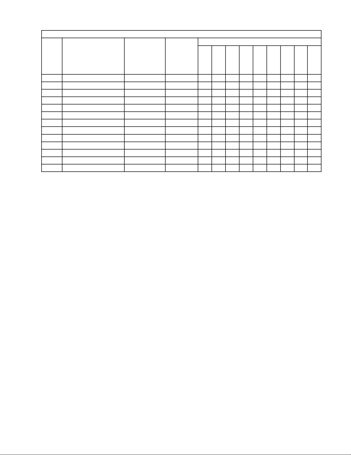
Title: A. Ice Cuber Assembly Model: KM-650MAH
Required Number
S-2
(L)
Index
No. Description
18 Air Filter - 2A2062G01 2 2 2 2 2 2 2 2
19 Push Retainer PS125306PG 4A2414-01 6 6 6 6 6 6 6 6
20 Bushing SR-34-2 420472-05 1 1 1 1 1 1 1 1
21 Cable Tie CV-200 8911-0200 1 1 1 1 1 1 1 22 Barrier GS 4A0352-01 1 1 1 1 1 1 1 1
22a T2 Screw 4×8 7P31-0408 2 2 2 2 2 2 2 2
23 Gasket L=554 4A0808L02 1 1 1 1 1 1 1 1
24 Barrier-Insulation GS 4A1167-01 1 1 1 1 1 1 1 1
24a T2 Screw 4×8 7P31-0408 2 2 2 2 2 2 2 2
25 Bin Control - 2A4393G01 1 - 1 1 1 1 1
26 Thumbscrew Black 415949G10 1 7 1 7 7 7 6 6
27 Capillary Ring - 425307-01 1 1 1 1 1 1 28 Base Side Panel (R) - 2A2147-01 1 1 1 1 1 1 1 1
Material or
Model Number Part Number
R-0
S-1
S-2
(E)
to
U-0
U-1
(B-H)
U-1
(J)
U-1
(K-L)
U-1
(M)
to
V-1
V-2
to
V-4
7
A. Ice Cuber Assembly
KM-650MWH
R-0 to V-4
F
8
7a
14
7
16
E
G
R-0 to V-1
15
16a
G1
6
5
13
11
1
11a
9
D1
D
19
R-0 to V-1
C
3
B
21
26
25
R-0 to U-1 (L)
U-1 (M) and Later
4a
R-0 to V-1
4
4b
23
20
22
24
2a
2
27
For thermostat, see
"D. Control Box Assembly"
R-0 to T-0
12
U-1 & later
10
10a
25
17
18
25
23
25
8
Title: A. Ice Cuber Assembly Model: KM-650MWH
Required Number
U-1
R-0
Index
No. Description
B Refrigeration Circuit - 1A1212A01 1 -
C Water Circuit - 1A0283A08 1 1 1 1 -
D Control Box Assembly - 2A3855A02 1 -
D1 T2 Screw 4×8 7P31-0408 3 3 3 3 3
E Label Location - 3A4025A01 1 -
F Top Panel Assembly SS 3A3878A01 1 1 1 1 1
G Front Panel Assembly SS 2A2253G01 1 1 1 1 -
G1 Truss Head Screw 4×8 SS 7C32-0408 1 1 1 1 1
Material or
Model Number Part Number
1A1662A01 1 1 1 1A1990A01 1
1A0283A02 1
2A3855A04 1 1 1 -
2A6056A02 1
3A5129A01 1 3A5608A01 1 1 3A5920A01 1
3A5997G01 1
to
T- 0
U-1
(F-H)
U-1
(J-L)
(M)
to
V-1
V-2
to
V-4
1 Evaporator Case - 1A0579G02 1 1 1 1 1
2 Base (includes item 27) - 2A2146G08 1 -
2A4319G04 1 1 2A5295G01 1 1
2a FT Screw 4×8 7F31-0408 7 7 7 7 7
3 Base Cover SS 321525G01 1 1 1 1 1
4 Frame ABS 3A2503G01 1 1 1 -
3A5600G01 1 1
4a Truss Head Screw 4×8 SS 7C32-0408 1 1 1 1 1
4b Truss Head Screw 4×25 SS 7C32-0425 2 2 2 2 2
5 Square Washer Brass 433537-02 1 1 1 1 1
6 Grounding Screw Brass 433304-02 1 1 1 1 1
7 Junction Box Cover GS 433410-01 1 1 1 1 1
7a T2 Screw 4×8 7P31-0408 1 1 1 1 1
8 Top Insulation - 215730G01 1 1 1 1 1
9 Front Insulation - 215731G02 1 1 1 1 1
10 Side Panel (R) SS 2A2117G02 1 1 1 1 1
10a T2 Screw 4×8 SS 7P32-0408 1 1 1 1 1
11 Control Box Cover GS 3A2371-01 1 1 1 1 1
11a T2 Screw 4×8 7P31-0408 3 3 3 3 3
12 Bulb Holder - 3A3903-01 1 -
Bin Control Switch Mount - 3A4463-01 1 1 1 1
13 Bushing SR-34-2 420472-05 1 1 1 1 1
14 Cable Tie
15 Air Filter - 2A2062G01 1 1 1 1 16 Barrier-Insulation GS 4A1167-01 1 1 1 1 1
16a T2 Screw 4×8 7P31-0408 2 2 2 2 2
CV-200
8911-0200 1 1 1 1 -
9
Title: A. Ice Cuber Assembly Model: KM-650MWH
Required Number
U-1
R-0
Index
No. Description
17 Louver - 1A0547-01 1 1 1 1 18 Gasket L=554 4A0808L02 1 1 1 1 1
19 Push Retainer PS125306PG 4A2414-01 3 3 3 3 -
20 Thumbscrew Black 415949G11 2 -
21 Foam Seal L=270 8208-0005 1 1 1 1 1
22 Silicone Hose L=380 7730I3812 1 -
23 Strap - 435487-01 1 1 1 24 Bin Control - 2A4393G01 1 1 1 1
25 Thumbscrew Black 415949G10 1 7 7 6 6
26 Capillary Ring - 425307-01 1 1 1 -
27 Base Side Panel (R) - 2A2147-01 1 1 1 1 1
Material or
Model Number Part Number
L=325 7730-1114 1 -
to
T- 0
U-1
(F-H)
U-1
(J-L)
(M)
to
V-1
V-2
to
V-4
10
A. Ice Cuber Assembly
KM-650MRH
R-0 to V-4
F
9
E
17
G
10
17a
G1
12
12a
C
13
1
4
5
6a
6
14
7
D1
D
8
B
R-0 to V-1
19
18
R-0 to V-1
R-0 to V-1
20
3
16
U-2 (M) and Later
R-0 to U-2 (L)
3b3a
27
23
For thermostat,
see "D. Control
Box Assembly"
11
26
15
21
22
26
2
R-0 to U-0
23
2a
25
24
28
U-1 & later
26
11
11a
26
Title: A. Ice Cuber Assembly Model: KM-650MRH
Required Number
U-2
R-0
Index
No. Description
B Refrigeration Circuit - 1A1214A01 1 1 -
C Water Circuit - 1A0283A08 1 1 1 1 1 -
D Control Box Assembly - 2A3855A02 1 -
D1 T2 Screw 4×8 7P31-0408 3 3 3 3 3 3
E Label Location - 3A4026A01 1 -
F Top Panel Assembly SS 3A3878A01 1 1 1 1 1 1
G Front Panel Assembly SS 2A2253G01 1 1 1 1 1 -
G1 Truss Head Screw 4×8 SS 7C32-0408 1 1 1 1 1 1
Material or
Model Number Part Number
1A1863A01 1 1 1 1A1999A02 1
1A0283A02 1
2A3855A04 1 1 1 1 2A6056A03 1
3A5140A01 1 1 3A5609A01 1 1 3A5944A01 1
3A5997G01 1
to
U-0 U-1
U-2
(G-H)
U-2
(J-L)
(M)
to
V-1
V-2
to
V-4
1 Evaporator Case - 1A0579G02 1 1 1 1 1 1
2 Base (includes item 28) - 2A2146G16 1 -
2A4319G10 1 1 1 2A5295G07 1 1
2a FT Screw 4×8 7F31-0408 7 7 7 7 7 7
3 Frame ABS 3A2503G01 1 1 1 1 -
3A5600G01 1 1
3a Truss Head Screw 4×8 SS 7C32-0408 1 1 1 1 1 1
3b Truss Head Screw 4×25 SS 7C32-0425 2 2 2 2 2 2
4 Square Washer Brass 433537-02 2 2 2 2 2 2
5 Grounding Screw Brass 433304-02 2 2 2 2 2 2
6 Junction Box Cover GS 433410-01 2 2 2 2 2 2
6a T2 Screw 4×8 7P31-0408 2 2 2 2 2 2
7 Bushing SR-34-2 420472-05 1 1 1 1 1 1
8 Base Cover SS 321525G01 1 1 1 1 1 1
9 Top Insulation - 215730G01 1 1 1 1 1 1
10 Front Insulation - 215731G02 1 1 1 1 1 1
11 Side Panel (R) SS 2A2117G02 1 1 1 1 1 1
11a T2 Screw 4×8 SS 7P32-0408 1 1 1 1 1 1
12 Control Box Cover GS 3A2371-01 1 1 1 1 1 1
12a T2 Screw 4×8 7P31-0408 3 3 3 3 3 3
13 Cable Tie
14 Bushing SR-30-1 420472-03 1 1 1 1 1 1
15 Foam Seal L=270 8208-0005 1 1 1 1 1 1
16 Gasket L=554 4A0808L02 1 1 1 1 1 1
17 Barrier-Insulation GS 4A1167-01 1 1 1 1 1 1
17a T2 Screw 4×8 7P31-0408 2 2 2 2 2 2
CV-200
8911-0200 1 1 1 1 1 -
12
Title: A. Ice Cuber Assembly Model: KM-650MRH
Required Number
U-2
R-0
Index
No. Description
18 Louver - 1A0547-01 1 1 1 1 1 19 Air Filter - 2A2062G01 1 1 1 1 1 -
20 Push Retainer
21 Thumbscrew Black 415949G11 2 22 Silicone Hose L=380 7730I3812 1 -
23 Strap - 435487-01 1 1 1 1 24 Bulb Holder - 3A3903-01 1 -
Bin Control Switch Mount - 3A4463-01 1 1 1 1 1
25 Bin Control - 2A4393G01 1 1 1 1 1
26 Thumbscrew Black 415949G10 1 7 7 7 6 6
27 Capillary Ring - 425307-01 1 1 1 1 -
28 Base Side Panel (R) - 2A2147-01 1 1 1 1 1 1
Material or
Model Number Part Number
PS125306PG
L=325 7730-1114 1 1 -
4A2414-01 3 3 3 3 3 -
to
U-0 U-1
U-2
(G-H)
U-2
(J-L)
(M)
to
V-1
V-2
to
V-4
13
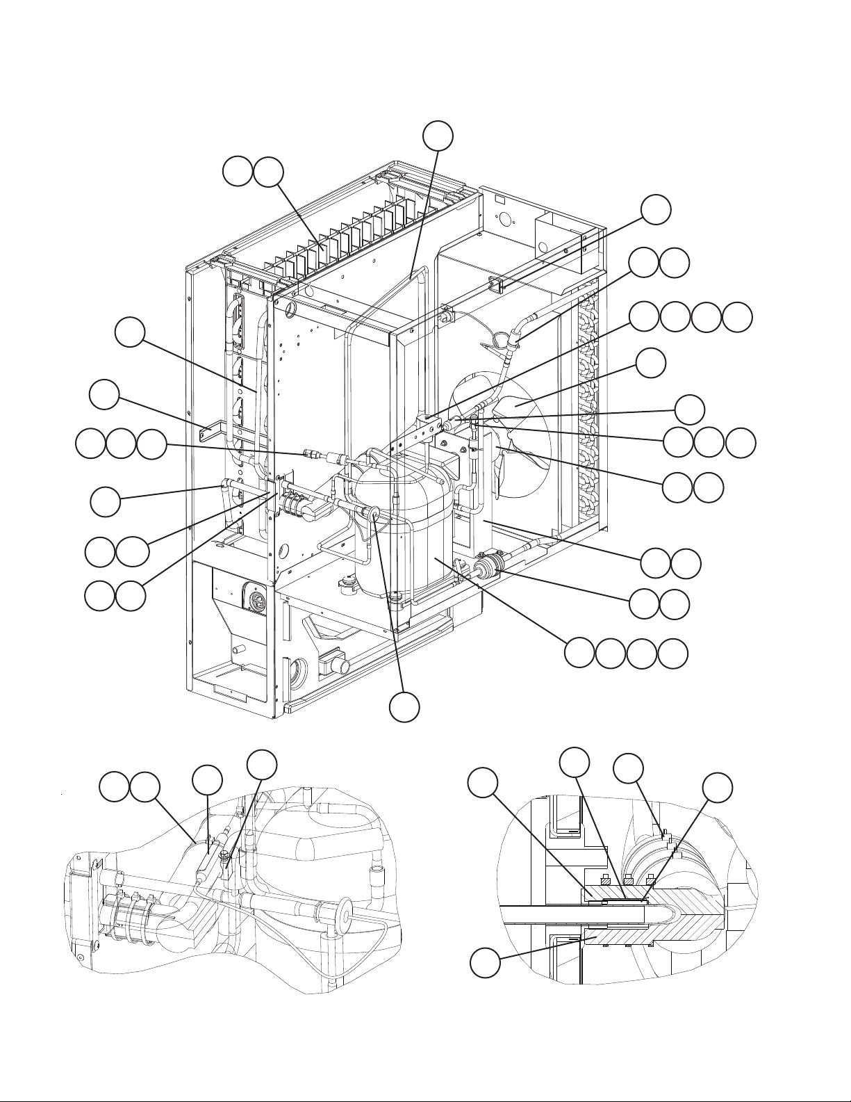
B. Refrigeration Circuit
KM-650MAH
1/2
R-0 to V-1
6
6a
5
26
27
28
6b
19 27
20
23a
23
21
17
22
28
12
7
8
8a
8b
4
11
19 27
2
3a
3
24
25
1
1a
1b
1c
28
2a
28
41
39
Detailed Expansion Valve Bulb
38
14
36
37
34
Detailed Thermistor Attachment
28
35
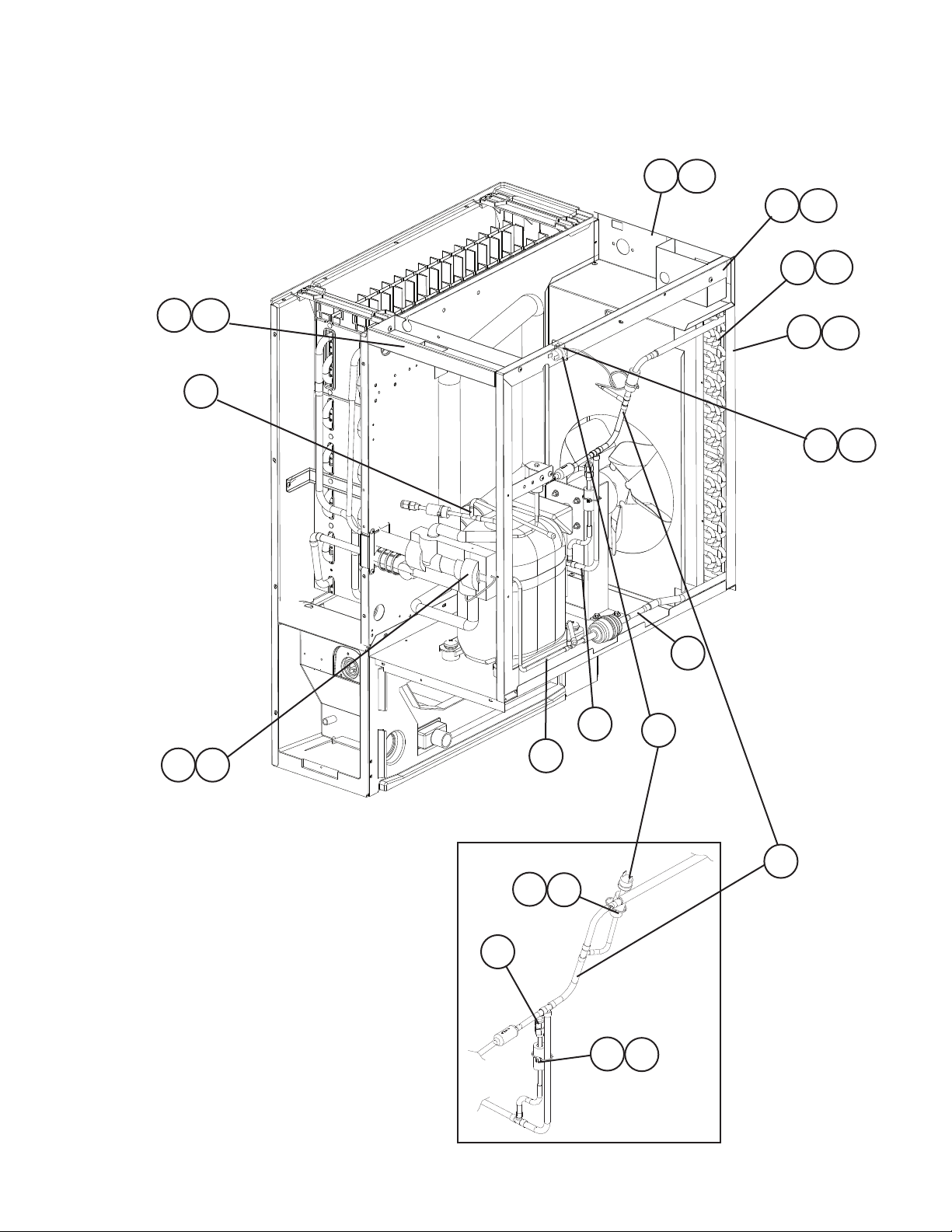
B. Refrigeration Circuit
KM-650MAH
2/2
R-0 to V-1
31a
31
30
30a
29
32
33
29a
32a
33a
18
R-0 to S-2 (E)
10a
10
R-0 to S-2 (E)
16
R-0 to S-2 (E)
13
4028
15
9
S-2 (L) to V-1
S-2 (L) to V-1
19
15
27
28
27
14
S-2 (L) to V-1
28
B. Refrigeration Circuit
KM-650MAH
1/2
V-2 to V-4
31a
31
42a
42
30
30a
26
29
33
29a
33a
23
21
28
40
23a
22
39
36
37
27
28
24
1
7
25
1a
8
1b
8a
1c
27
11
2
3
8b
4
28
2a
3a
16

B. Refrigeration Circuit
KM-650MAH
2/2
V-2 to V-4
6
17
18
6a
5
14
19
32a
32
6b
35
38
19
41
12
13
9
16
15
34
Detailed Expansion Valve Bulb
and Thermistor Attachment
17

Title: B. Refrigeration Circuit Model: KM-650MAH
Required Number
S-2
R-0
(L)
U-1
to
to
(K)
Index
No. Description
1 Compressor
1a Spacer - 434404-01 4 4 4 -
1b Grommet - 434403-01 4 4 4 -
1c Bolt 8×45 437889-01 4 4 4 4 4
2 Fan Motor 50 WATT–GEHI 4A3158-01 1 1 1 1 1
2a Self-Locking Nut NO.8-32 7N21I0832 4 4 4 4 4
3 Fan Motor Bracket GS 327180-01 1 1 1 1 1
3a Hex Head Bolt w/Washer
(LF)
4 Fan Blade - 4A3959-01 1 1 1 1 1
5 Heat Exchanger - 2A3850G01 1 1 1 -
6 Evaporator - 106396G01 1 1 1 1 1
6a T2 Screw 4×16 SS 7P32-0416 4 4 4 4 4
6b T2 Screw 4×12 SS 7P32-0412 2 2 2 2 2
7 Valve Body-Hot Gas - 4A3978-01 1 1 1 1 1
8 Coil-Valve - 4A3277-01 1 1 1 1 1
8a Bolt - 4A3277F01 1 1 1 1 1
8b Truss Head Screw 4×8 7C31-0408 2 2 2 2 2
9 Pressure Switch - 433441-07 1 -
10 Pressure Switch Bracket GS 434938-01 1 -
10a T2 Screw 4×8 7P31-0408 1 -
11 Strainer 5/16 441569-02 1 1 1 1 1
12 Expansion Valve HFE-15 NHD-2 4A1482-01 1 1 1 1 1
13 Copper Tube (A)-High
Side
14 Copper Tube (C)-High
Side
15 Copper Tube (E)-High
Side
Copper Tube (B)-High
Side
16 Copper Tube (F)-High
Side
17 Copper Tube-Low Side - 3A1193G01 1 1 1 -
Copper Tube-Hot Gas - 2A4588G02 1 1
18 Copper Tube-Access
Val ve
19 Access Valve - 457729-01 2 2 2 2 2
20 Elbow - 417395-03 1 1 21 Rubber Insulation (A) - 3A1044-01 1 1 1 1 1
Material or
Model Number Part Number
RS55C2E-CAV-219
RST61C1E-CAV-202
5×12 7B0130512 4 4 4 4 4
- 3A4016G01 1 1 1 -
- 3A4004G01 1 -
- 3A1213G03 1 1 1 -
- 3A4803G01 1 1
- 4A4084-01 1 1 1 1 1
- 4A2025G01 1 1 1 -
4A4072-01 1 1 1 4A5079-01 1 1
4A2595-01 4 4
4A2593-01 4 4
2A5448G02 1 1
463180-04 1 1 1 1
3A5973G01 1 1
3A4475G01 1 1 3A5999-01 1 1
3A5967G01 1 1
S-2
(E)
U-1
(J)
to
V-1
V-2
V-3 V-4
18

Title: B. Refrigeration Circuit Model: KM-650MAH
Required Number
S-2
R-0
(L)
U-1
to
to
(K)
Index
No. Description
22 Rubber Insulation (B) - 3A1045-01 1 1 1 1 1
23 Insulation Holder SS 4A1550-01 1 1 1 1 1
23a T2 Screw 4×8 SS 7P32-0408 2 2 2 2 2
24 Drier - 4A2666-01 1 1 1 1 1
25 Nylon Tie - 8911-0301 1 1 1 1 1
26 Clamp - 4A2338-01 1 1 1 1 1
27 Insulation Tube L=40 7762-1020 3 3 3 3 3
28 Cable Tie CV-200 8911-0200 12 12 12 12 12
29 Side Frame GS 2A1301G01 1 1 1 1
29a T2 Screw 4×8 7P31-0408 4 4 4 4 4
30 Shroud Assembly - 2A3849G01 1 1 1 -
30a T2 Screw 4×8 7P31-0408 5 5 5 5 5
31 Top Frame (A) GS 3A1893-01 1 1 1 1 1
31a T2 Screw 4×8 7P31-0408 4 4 4 4 4
32 Condenser - 2A3853-01 1 1 1 -
32a T2 Screw 4×8 7P31-0408 4 4 4 4 4
33 Barrier GS 433693-02 1 1 1 - 1
33a T2 Screw 4×8 7P31-0408 2 2 2 2 2
34 Thermistor L=1050 429006-03 1 1 1 1 1
35 Thermistor Holder - 427430-01 1 1 1 1 1
36 Thermistor Insulation-(A) - 439368-01 1 1 1 1 1
37 Thermistor Insulation-(B) - 439368-02 1 1 1 1 1
38 Expansion Valve Bulb
Holder
39 Insulation Tube L=200 7762-3555 1 1 1 1 1
40 Expansion Valve Cover - 3A0944-01 1 1 1 1 1
41 Clamp NO# 6806 443461-02 1 1 1 1 1
42 Hot Gas Valve Bracket - 4A0145-01 1
42a T2 Screw 4×8 7P31-0408 2
Material or
Model Number Part Number
2A6209-01 - 1
2A5994G01 1 1
2A5870-01 1 1
4A5119-01 1 -
- 3A0107-01 1 1 1 1 1
S-2
(E)
U-1
(J)
to
V-1
V-2
V-3 V-4
19

B. Refrigeration Circuit
KM-650MWH
1/2
R-0 to V-1
20
6
6a
21
13 39
6b
36
7
14
23
22
15
3937
22a
15a
29
29a
1
5
1a
2827
1b 1c
38 39
24
25
12
19
30
2a
2
13 37 39
17
37 39
3
4
9a
9
8
9b
39
31
Detailed Expansion Valve Bulb
32
33
Detailed Thermistor Attachment
20

B. Refrigeration Circuit
KM-650MWH
2/2
R-0 to V-1
41a
41
40
R-0 to T-0
40a
34
42
42a
26
39
U-1 to V-1
R-0 to T-0
16
U-1 to V-1
R-0 to T-0
18
R-0 to T-0
10
11
35
11a
3937
13
3937
U-1 to V-1
21
U-1 to V-1
18
35
16

B. Refrigeration Circuit
KM-650MWH
1/2
V-2 to V-4
37
21
39
41
41a
37 39
34
40
40a
22
42
14
23
42a
15
22a
15a
35
26
39
8
37 39
9a
9
9b
29
29a
32 33
22
1
38 39
1a
43
1b 1c
43a
2827

B. Refrigeration Circuit
KM-650MWH
2/2
V-2 to V-4
6
12
6b
6a
20
13
10
31
24
25
18
35
7
2a
2
5
13
17
3
16
4
19
30
Detailed Expansion Valve Bulb
and Thermistor Attachment
23

Title: B. Refrigeration Circuit Model: KM-650MWH
Required Number
U-1
(K)
Index
No. Description
1 Compressor
1a Spacer - 434404-01 4 4 4 -
1b Grommet - 434403-01 4 4 4 -
1c Bolt 8×45 437889-01 4 4 4 4 4
2 Condenser-Water Cooled HS-0161 2A2359G02 1 1 1 1 1
2a Hex Bolt 5×10 7B0130510 2 2 2 2 2
3 Drier - 4A2666-01 1 1 1 1 1
4 Nylon Tie - 8911-0301 1 1 1 1 1
5 Expansion Valve HFE-15 NHD-2 4A1482-01 1 1 1 1 1
6 Evaporator - 106396G01 1 1 1 1 1
6a T2 Screw 4×16 SS 7P32-0416 4 4 4 4 4
6b T2 Screw 4×12 SS 7P32-0412 2 2 2 2 2
7 Strainer 5/16 441569-02 1 1 1 1 1
8 Hot Gas Valve Body - 4A3978-01 1 1 1 1 1
9 Valve Coil - 4A3277-01 1 1 1 1 1
9a Bolt - 4A3277F01 1 1 1 1 1
9b Truss Head Screw 4×8 7C31-0408 2 2 2 2 2
10 Pressure Switch - 433441-05 1 -
11 Pressure Switch Bracket GS 434938-01 1 -
11a T2 Screw 4×8 7P31-0408 1 -
12 Copper Tube-Access Valve - 4A2025G01 1 1 1 -
13 Access Valve - 457729-01 2 2 2 2 2
14 Male Connector - 4A1087-01 1 1 1 1 1
15 Water Regulator - 4A0911-07 1 1 1 1 1
15a Truss Head Screw 4×6 7C31-0406 2 2 2 2 2
16 Copper Tube (A)-High Side - 3A4016G01 1 -
17 Copper Tube (B)-High Side - 4A2723G01 1 1 1 1 1
18 Copper Tube (C)-High Side - 3A3946G01 1 -
Copper Tube (C1) 3A5506-01 1 1 1 1
19 Copper Tube (E)-High Side - 3A1213G01 1 1 1 -
Copper Tube (B)-High Side 3A4803G01 1 1
20 Heat Exchanger - 2A3850G02 1 1 1 -
21 Copper Tube-Low Side - 3A1193G01 1 1 1 -
Copper Tube-Hot Gas 2A4588G01 1 1
22 Copper Tube (A)-Water
Circuit
22a Truss Head Screw 4×8 7C31-0408 2 2 2 2 2
Material or
Model Number Part Number
RS55C2ECAV-219
RST61C1E-CAV-202
- 3A2190G01 1 1 1 1 1
4A4072-01 1 1 1 4A5079-01 1 1
4A2595-01 4 4
4A2593-01 4 4
463180-05 1 1 1 1
3A5967G01 1 1
3A5508G01 1 1 3A5973G01 1 1
2A5448G02 1 1
R-0
to T-0
U-1
(F-J)
to
V-1
V-2
V-3 V-4
24

Title: B. Refrigeration Circuit Model: KM-650MWH
Required Number
U-1
(K)
Index
No. Description
23 Copper Tube (B)-Water
Circuit
24 Clamp - 443461-02 1 1 1 1 1
25 Expansion Valve Bulb
Holder
26 Expansion Valve Cover - 3A0944-01 1 1 1 1 1
27 Rubber Insulation (A) - 3A1044-01 1 1 1 1 1
28 Rubber Insulation (B) - 3A1045-01 1 1 1 1 1
29 Insulation Holder SS 4A1550-01 1 1 1 1 1
29a T2 Screw 4×8 SS 7P32-0408 2 2 2 2 2
30 Thermistor L=1050 429006-03 1 1 1 1 1
31 Thermistor Holder CU 427430-01 1 1 1 1 1
32 Thermistor Insulation-(A) - 439368-01 1 1 1 1 1
33 Thermistor Insulation-(B) - 439368-02 1 1 1 1 1
34 Clamp - 4A2338-01 1 1 1 1 1
35 Elbow - 417395-02 1 1 1 1 1
36 Elbow - 417395-03 1 1 37 Insulation Tube L=40 7762-1020 3 3 3 4 4
38 Insulation Tube L=250 7762-3555 1 1 1 1 1
39 Cable Tie CV-200 8911-0200 13 13 13 13 13
40 Rear Panel GS 2A2437G01 1 1 1 1 1
40a T2 Screw 4×8 7P31-0408 5 5 5 5 5
41 Top Frame GS 3A1893-01 1 1 1 1 1
41a T2 Screw 4×8 7P31-0408 4 4 4 4 4
42 Side Frame GS 2A1301G01 1 1 1 1 -
42a T2 Screw 4×8 7P31-0408 4 4 4 4 4
43 Hot Gas Valve Bracket - 4A0145-01 1
43a T2 Screw 4×8 7P31-0408 2
Material or
Model Number Part Number
- 3A2191G01 1 1 1 1 1
- 3A0107-01 1 1 1 1 1
2A6209-01 1
R-0
to T-0
U-1
(F-J)
to
V-1
V-2
V-3 V-4
25

B. Refrigeration Circuit
KM-650MRH
1/2
R-0 to V-1
16
27
10
10a
26
22
5
5a
37
10b
35
30
37a
36
28
45
25
4
2
24
45
43
6
6a
13
8
7
23
12b
12a
12
11
9
19
19a
12a
46
12b
1a
1
2912
1b
1c
3a
3
44
45
38
17
Detailed Expansion Valve Bulb Detailed Thermistor Attachment
26
45
32
31
33
34

B. Refrigeration Circuit
KM-650MRH
2/2
R-0 to V-1
40
40a
42
42a
41
41a
18
45
U-2 to V-1
43
45
U-2 to V-1
R-0 to U-1
20
R-0 to U-1
14
R-0 to U-1
R-0 to U-1
21
15
39
15a
27
U-2 to V-1
U-2 to V-1
21
20

B. Refrigeration Circuit
KM-650MRH
1/2
V-2 to V-4
41a
41
45
43
26
40
40a
39
42
42a
35
36
18
37
33
44
45
37a
34
45
19
48
48a
28

B. Refrigeration Circuit
KM-650MRH
2/2
V-2 to V-4
10
27
10a
16
14
22
5
4
5a
10b
17
2
3a
3
9
24
20
21
6
6a
13
49
28
1a
1
1b
1c
11
7
8
12b
12a
12
23
47
12b
12a
2912
32
31
38
Detailed Expansion Valve Bulb
and Thermistor Attachment
29

Title: B. Refrigeration Circuit Model: KM-650MRH
Required Number
U-2
R-0
Index
No. Description
1 Compressor
1a Spacer - 434404-01 4 4 4 -
1b Grommet - 434403-01 4 4 4 -
1c Bolt 8×45 437889-01 4 4 4 4 4
2 Coupling - 434136G01 1 1 1 1 1
3 Tube Holder-L GS 438245-01 1 1 1 1 1
3a T2 Screw 4×8 7P31-0408 2 2 2 2 2
4 Coupling - 4A3972G01 1 1 1 1 1
5 Tube Holder-S GS 438246-01 1 1 1 1 1
5a T2 Screw 4×8 7P31-0408 2 2 2 2 2
6 Receiver Tank - 437652-01 1 1 1 1 1
6a Hex Bolt 5×10 (LF) 7B0130510 3 3 3 3 3
7 Drier - 4A2666-01 1 1 1 1 1
8 Nylon Tie - 8911-0301 1 1 1 1 1
9 Expansion Valve HFE-15 NHD-2 4A1482-01 1 1 1 1 1
10 Evaporator - 106396G01 1 1 1 1 1
10a T2 Screw 4×16 SS 7P32-0416 4 4 4 4 4
10b T2 Screw 4×12 SS 7P32-0412 2 2 2 2 2
11 Hot Gas Valve Body ATS-B7SHDU-2 4A3978-01 1 1 1 1 1
12 Valve Coil - 4A3277-01 2 2 2 2 2
12a Bolt - 4A3277F01 2 2 2 2 2
12b Truss Head Screw 4×8 7C31-0408 4 4 4 4 4
13 Strainer - 441569-02 1 1 1 1 1
14 Pressure Switch - 433441-07 1 -
15 Pressure Switch Bracket GS 434938-01 1 15a T2 Screw 4×8 7P31-0408 1 -
16 Heat Exchanger - 2A3850G03 1 1 1 -
17 Expansion Valve Bulb
Holder
18 Expansion Valve Cover - 3A0944-01 1 1 1 1 1
19 Crankcase Heater - 434186-01 1 1 1 -
19a T2 Screw 4×8 7P31-0408 1 1 1 -
20 Copper Tube (A)-High
Side
21 Copper Tube (C)-High
Side
22 Copper Tube (D)-High
Side
23 Copper Tube (E)-High
Side
Material or
Model Number Part Number
RS55C2E-CAV-219
RST61C1E-CAV-202
- 3A0107-01 1 1 1 1 1
- 3A4016G02 1 -
- 4A4096-01 1 1 1 1 1
- 3A4046G01 1 1 1 1 1
- 3A2309-01 1 1 1 -
4A4072-01 1 1 1 4A5079-01 1 1
4A2595-01 4 4
4A2593-01 4 4
463180-04 1 1 1 1
2A5448G02 1 1
4A5091-01 1 1
3A5508G02 1 1 3A5973G01 1 1
4A5116-01 1 1
to
U-1
U-2
(G-J)
(K)
to
V-1
V-2
V-3 V- 4
30

Title: B. Refrigeration Circuit Model: KM-650MRH
Required Number
U-2
R-0
Index
No. Description
24 Copper Tube (G)-High
Side
25 Copper Tube-Low Side - 3A1193G01 1 1 1 26 Copper Tube-Hot Gas - 4A4085-01 1 1 1 -
27 Copper Tube-Access
Val ve
28 Access Valve - 457729-01 1 1 1 1 1
29 Line Valve Body ATS-B7SHDU-1 4A3276-01 1 1 1 1 1
30 Elbow - 417395-03 1 1 31 Thermistor - 429006-03 1 1 1 1 1
32 Thermistor Holder - 427430-01 1 1 1 1 1
33 Insulation-Thermistor (A) - 439368-01 1 1 1 1 1
34 Insulation-Thermistor (B) - 439368-02 1 1 1 1 1
35 Rubber Insulation (A) - 3A1044-01 1 1 1 1 1
36 Rubber Insulation (B) - 3A1045-01 1 1 1 1 1
37 Insulation Holder SS 4A1550-01 1 1 1 1 1
37a T2 Screw 4×8 SS 7P32-0408 2 2 2 2 2
38 Clamp #6806 443461-02 1 1 1 1 1
39 Clamp - 4A2338-01 1 1 1 1 1
40 Rear Panel GS 2A1328G01 1 1 1 1 1
40a T2 Screw 4×8 7P31-0408 5 5 5 5 5
41 Top Frame GS 3A1893-01 1 1 1 1 1
41a T2 Screw 4×8 7P31-0408 4 4 4 4 4
42 Side Frame GS 2A1301G02 1 1 1 1 -
42a T2 Screw 4×8 7P31-0408 4 4 4 4 4
43 Insulation Tube L=40 7762-1020 1 1 1 2 2
44 Insulation Tube L=250 7762-3555 1 1 1 1 1
45 Cable Tie CV-200 8911-0200 11 11 11 11 11
46 Silicone Hose L=50 7730I3812 1 1 1 47 Copper Tube (W)-High
Side
48 Hot Gas Valve Bracket - 4A0145-01 2
48a T2 Screw 4×8 7P31-0408 4
49 Copper Tube (A) High
Side (Process Tube)
Material or
Model Number Part Number
- 3A4015G01 1 3A5507G01 1 1 3A6000G01 1 1
2A6049G01 1 1
- 4A2025G01 1 1 1 -
3A5967G01 1 1
2A6209-01 1
- 4A5117-01 1 1
- 4A5115-01 1 1
to
U-1
U-2
(G-J)
(K)
to
V-1
V-2
V-3 V- 4
31

C. Water Circuit
KM-650MAH, KM-650MWH, KM-650MRH
R-0 toV-4
7
42
8
41
24
2a
12
43
12
39
33
14
14a
22a
27
6
5
1
12
38
15
28
32
16
13
46
45
37
46
47
47
12
40
30
44
29
26
17
36
35
3
4
36a
35a
18
19
34
4a
34a
31
2
9
22
21
12
11
11a
H
23
H2
H1
25
20
H4
H3
10
32

Title: C. Water Circuit Model: KM-650MAH, KM-650MWH, KM-650MRH
R-0
Index
No. Description
H Pump Motor Assembly HS-0176 3A2638A03 1 1
H1 Truss Head Screw 4×16 SS 7C32-0416 4 4
H2 Flat Washer M4 SS 7W22-0400 4 4
H3 Split Lock Washer M4 SS 7L22-0400 4 4
H4 Hex Nut M4 SS 7N12-0400 4 4
1 Rubber Hose (A) EPDM 4A1551-01 1 1
2 Water Supply Pipe Copper 4A0768G04 1 1
2a T2 Screw 4×8 7P31-0408 2 2
3 Rubber Gasket SI.R 413854-03 1 1
4 Water Valve Bracket GS 321443-01 1 1
4a T2 Screw 4×8 7P31-0408 1 1
5 Water Valve J248-033 3U0111-03 1 -
6 Hose Clamp 18 mm SS 427443-05 1 1
7 Spray Tube PE 1A0260-02 1 1
8 Spray Guide (A) PE 208586-01 6 6
9 Cube Guide ABS 212088-01 1 1
10 Suction Hose EPDM 433466-01 1 1
11 Pump Motor Bracket ABS 211408-01 1 1
11a Flat Head Screw 4×12 SS 7C22-0412 1 1
12 Hose Clamp 25 mm SS 427443-03 9 9
13 "O" Ring 1AG35 7611-G035 1 1
14 Valve Housing-Drain ABS 321001-01 1 1
14a T2 Screw 4×10 SS 7P32-0410 3 3
15 Spring SS 322110-01 1 1
16 Valve Seat EPDM 433705-01 1 1
17 Drain Hose Santoprene 433468-01 1 1
18 Overow Cap PE 321002-01 1 1
19 Overow Pipe ABS 430722-01 1 1
20 "O" Ring EPDM, AS568-
21 Float Switch Connector - 426799-01 1 1
22 Float Switch 213095 4A3624-01 1 1
22a T2 Screw 4×12 SS 7P32-0412 2 2
23 Vinyl Hose L=110 7716-2025 1 1
24 Bushing OCB-875 428394-04 1 1
25 Corner Insulation (A) PE Foam 439376-01 1 1
26 Corner Insulation (B) PE Foam 439392-01 1 1
27 Tee Santoprene 4A0177-01 1 1
28 Flange EPDM 439267-01 1 1
29 Rubber Hose (B) EPDM 4A1551-02 1 1
30 Rubber Ring EPDM 439236-01 1 1
31 Wire Saddle VS-4238-M 4A0338-02 4 4
32 Ball Valve Assembly
(includes items 45
through 47)
33 Silicone Hose L=140 7730I3812 1 1
Material or
Model Number Part Number
J248-032 3U0111-02 1
4A1234-01 1 1
218
S-0761 442137A01 1 1
to
V-1
Required Number
V-2
to
V-4
33

Title: C. Water Circuit Model: KM-650MAH, KM-650MWH, KM-650MRH
R-0
Index
No. Description
34 Handle PE 215383-01 1 1
34a T2 Screw 4×8 7P31-0408 1 1
35 Valve Holder GS 3A1178-01 1 1
35a FT Screw 4×8 SS 7F32-0408 3 3
36 Microswitch
36a Tapping Screw 3×14 431415-02 2 2
37 Insulation (E) - 4A0392-01 1 1
38 Hose Clamp 20 mm SS 427443-06 1 1
39 Silicone Hose L=140 7730I3896 1 1
40 Vinyl Hose L=250 7716-2025 1 1
41 Water Supply Tube PE 2A0079-01 1 1
42 Plug Santoprene 4A0176-01 2 2
43 Distributor ABS 432426-01 1 1
44 Insulation Tube L=370 7762-2636 1 1
45 Ball Valve - 439293-01 1 1
46 Male Adaptor - 325826-01 2 2
47 "O" ring - 7611-P018 2 2
Material or
Model Number Part Number
V7-1C17D8-207
4A2546-01 1 1
to
V-1
Required Number
V-2
to
V-4
34

D. Control Box Assembly
KM-650MAH
R-0 to V-1
2
1
12
3a
3
14
9
9a
7
10
10a
6a
6
13
11
15
18
4a
4
12
16 17
8a
8
5
18a
13
20
12
19
12
35

D. Control Box Assembly
KM-650MAH
V-2 to V-4
12
2
1
10
10a
21
21a
6a
6
11
4a
4
12
16 17
15
3a
3
14
7
9a
9
5
13
V-3 and Later
13
12
20
V-2
8a
8
12
36

Title: D. Control Box Assembly Model: KM-650MAH
Index
No. Description
1 Control Box GS 3A2372G02
2 Start Capacitor 175-216MFD
3 Strap GS 4A2262-03
3a T2 Screw 4×8 7P31-0408
4 Starter GE#
4a T2 Screw 4×8 7P31-0408
5 Toggle Switch EATON
6 Transformer 26D285H 3A0172-01
6a T2 Screw 4×8 7P31-0408
7 Board Support CBLS37-M 4A0336-03
8 Magnetic Contactor VC20 428393-01
Compressor Relay 4A3140-01
8a T2 Screw 4×8 7P31-0408
9 Pump Motor Capacitor 5.5MFD 250VAC 443192-03
9a T2 Screw 4×10 7P31-0410
10 Fan Motor Capacitor 5.0MFD 250VAC 443192-02
10a T2 Screw 4×10 7P31-0410
11 Bushing OCB-500 428394-02
12 Bushing OCB-875 428394-04
13 Wire Saddle VS-4238-M 4A0338-02
14 Run Capacitor 25MFD 370VAC 3A2005-06
15 Control Board "E" Board 2A1410-01
16 Fuse Holder HTB82I 4A3449-01
17 Fuse AGC - 10 250V
18 Thermostat YTB-3U112 4A2879-01
18a Truss Head Screw 4×8 7C31-0408
19 Control Label - 4A1758-01
20 Wire Harness L=90 4A2200G04
21 Relay LY2F - AC 120V 406132-07
21a Tapping Screw 3×8 431415-01
Material or
Model Number Part Number
3A2372G04
3A6045G01
3A0076-19
330VAC
72-86MFD
330VAC
3ARR3CT10V5
3ARR3KC10A5 4A1107-19
#8966K84
17.5MFD 440V 3A2005-16
"G" Board 2A3792-01
10A
3A1414-01
4A2262-02
4A1107-12
443119-01
4A0893-07
Required Number
S-2
(L)
U-1
R-0
S-2
to
to
S-1
(E)
U-0
V-1 V- 2
1 - 1 -
1 - 1 -
1 1
1 1 1 1 -
1 1
1 1 1 1 -
1 1
1 1 1 1 1 1
1 1 1 1 -
1 1
1 1 1 1 1 1
1 1 1 1 1 1
1 1 1 1 1 1
2 2 2 2 2 2
4 4 4 4 4 4
1 1 1 1 1 -
2 2 2 2 2 2
1 1 1 1 1 1
1 1 1 1 1 1
1 1 1 1 1 1
1 1 1 1 1 1
1 1 1 1 1 1
4 4 4 4 4 4
2 2 2 2 2 2
1 1 1 1 -
1 1
1 - 1 -
1 - 1 1 1
1 1 1 1 1 1
1 1 1 1 1 1
1 - 1 -
2 - 2 -
1 - 1 -
1 - 1 1 1
2 2
4 4
V-3
V-4
1
37

D. Control Box Assembly
KM-650MWH, KM-650MRH
R-0 to V-1
2
1
11
3a
3
13
9
9a
7
6
6a
12
19
10
14
17
4a
4
11
15 16
8a
8
5
17a
12
11
18
11
38

D. Control Box Assembly
KM-650MWH, KM-650MRH
V-2 to V-4
1
11
2
20
20a
V-2
8a
10
6a
6
8
V-3 and Later
11
4a
4
15 16
14
12
3a
3
13
7
9a
9
5
12
19
11
11
39

Title: D. Control Box Assembly Model: KM-650MWH, KM-650MRH
R-0
Index
No. Description
1 Control Box GS 3A2372G02
2 Start Capacitor 175-216MFD
3 Strap GS 4A2262-03
3a T2 Screw 4×8 7P31-0408
4 Starter GE#
4a T2 Screw 4×8 7P31-0408
5 Toggle Switch EATON
6 Transformer 26D285H 3A0172-01
6a T2 Screw 4×8 7P31-0408
7 Board Support CBLS37-M 4A0336-03
8 Magnetic Contactor VC20 428393-01
Compressor Relay KM-650MWH 4A3140-01
8a T2 Screw 4×8 7P31-0408
9 Pump Motor Capacitor 5.5MFD 250VAC 443192-03
9a T2 Screw 4×10 7P31-0410
10 Bushing OCB-500 428394-02
11 Bushing OCB-875 428394-04
12 Wire Saddle VS-4238-M 4A0338-02
13 Run Capacitor 25MFD 370VAC 3A2005-06
14 Control Board "E" Board 2A1410-01
15 Fuse Holder HTB82I 4A3449-01
16 Fuse AGC - 10 250V
17 Thermostat YTB-3U112 4A2879-01
17a Truss Head Screw 4×8 7C31-0408
18 Control Label - 4A1758-01
19 Wire Harness L=90 4A2200G04
20 Relay LY2F - AC 120V 406132-07
20a Tapping Screw 3×8 431415-01
Material or
Model Number Part Number
3A2372G04
3A6045G01
3A0076-19
330VAC
72-86MFD
330VAC
3ARR3CT10V5
3ARR3KC10A5 4A1107-19
#8966K84
KM-650MRH 4A5096-01
17.5MFD 440V 3A2005-16
"G" Board 2A3792-01
10A
3A1414-01
4A2262-02
4A1107-12
443119-01
4A0893-07
U-0
Required Number
U-1
to
to
V-1 V-2
1 -
1 -
1 1
1 1 -
1 1
1 1 -
1 1
1 1 1 1
1 1 -
1 1
1 1 1 1
1 1 1 1
1 1 1 1
2 2 2 2
4 4 4 4
1 1 1 -
2 2 2 2
1 1 1 1
1 1 1 1
1 1 1 1
4 4 4 4
2 2 2 2
1 1 -
1 1
1 -
1 1 1
1 1 1 1
1 1 1 1
1 -
2 -
1 -
1 1 1
1 2
4 4
V-3
V-4
1
1
40

E. Label Location
KM-650MAH
R-0 to V-4
1
5
8
4
6
11
14
16
13
3
10
9
7
15
2
12
17
18
41

Title: E. Label Location Model: KM-650MAH
Index
No. Description
1
Emblem
2
Label-Alarm
3
Label-Penguin-HA-R
4
Label-Air Filter
5
Maintenance Label
6
Caution Label-K
Warning Label-K 4A4736-01
7
Wiring Label
8
Rating Label
9
Nameplate
10
Instruction Sheet
11
Tag Warning: Electrical
Connection
12
Manual Label
13
Operation Label-Valve
14
Label-R404A
15
Instruction Label
16
Caution Label (F)
Warning Label (F) 4A4767-01
17
Label-Control Board
18
Label-Fuse
Material or
Model Number Part Number
PETP Film
PVC Film
PETP Film
PETP Film
PVC Film
PVC Film
PES Film
PES Film
PES Film
Paper
Paper
PVC Film
PVC Film
PES Film
PVC Film
PVC Film
PVC Film
PVC Film
4A0560-01
4A3517-01
4A4737-01
4A0526-01
426177-01
326218-01
3A5404-01
439150-01
3A4029-01
3A4524-01
3A5912DEV
3A5912-01
2A3859-01
2A5918-01
2A3858-01
2A5919-01
2A4371-01
428430-01
4A4801-01
4A2864-01
4A4839-01
439541-01
4A4828-01
4A0960-01
444575-01
439146-01
3A2220-01
3A4799-01
4A2817-01
4A4829-01
Required Number
S-2
(L)
R-0
S-2
to
S-1
(E)
U-0
1 1 1 1 1 1 1
1 1 1 1 -
1 1 1 1 1 1 1
1 1 1 1 1 1 1
1 1 1 1 -
1 1 1 1 -
1 - 1 -
1 1 1 -
1 1 1 1 1 -
1 1 1 1 1 -
1 1 1 -
1 1 1 1 -
1 - 1 -
1 1 1 1 1
1 1 1 1 -
1 1 1 1 1 -
1 1 1 1 1 1 1
1 1 1 1 -
1 - 1 -
1 1 1 1 1
1 1 1 1 -
U-1
(B-H)
U-1
(J)
to
V-1 V- 2
1 1 1
1 1 1
1 1 1
1 -
1 1
1 1
1 1 1
1 1 1
1 1 1
1 1 1
V-3
V-4
1
42

E. Label Location
KM-650MWH
R-0 to V-4
1
4
7
12
9
13
5
3
8
10
14
2
15
6
11
43
16

Title: E. Label Location Model: KM-650MWH
Required Number
U-1
R-0
Index
No. Description
1 Emblem PETP Film 4A0560-01 1 1 1 1 1
2 Label-Alarm PVC Film 4A3517-01 1 1 -
3 Label-Penguin-HA-R PETP Film 4A0526-01 1 1 1 1 1
4 Maintenance Label PVC Film 326218-01 1 1 -
5 Caution Label-K PVC Film 439150-01 1 1 -
Warning Label-K 4A4736-01 1 1 1
6 Wiring Label PES Film 3A4029-01 1 -
7 Rating Label PES Film 2A3859-02 1 1 1 -
8 Nameplate PES Film 2A3858-02 1 1 1 -
9 Instruction Sheet Paper 2A4371-01 1 -
10 Tag-Warning: Electrical
Connecton
11 Manual Label PVC Film 4A2864-01 1 -
12 Operation Label-Valve PVC Film 439541-01 1 1 -
13 Label-R404A PES Film 4A0960-01 1 1 1 1 14 Instruction Label PVC Film 444575-01 1 1 1 1 1
15 Label-Control Board PVC Film 3A2220-01 1 -
16 Label-Fuse PVC Film 4A2817-01 1 1 -
Material or
Model Number Part Number
4A4737-01 1 1 1
3A5404-01 1 1 1
3A4524-01 1 1 3A5912DEV 1 3A5912-01 1
2A5918-02 1 1
2A5919-02 1 1
Paper 428430-01 1 1 -
4A4801-01 1 1 1
4A4839-01 1 1 1 1
4A4828-01 1 1 1
3A4799-01 1 1 1 1
4A4829-01 1 1 1
to
T- 0
U-1
(F-H)
(J)
to
V-1 V- 2
V-3
V-4
44

E. Label Location
KM-650MRH
R-0 to V-4
1
4
7
9
3
11
10
16
14
5
17
6
8
13
14
19
18
45
15
12
2

Title: E. Label Location Model: KM-650MRH
Required Number
U-2
R-0
Index
No. Description
1 Emblem PETP Film 4A0560-01 1 1 1 1 1 1
2 Label-Fuse PVC Film 4A2817-01 1 1 1 -
3 Label-Penguin-HA-R PETP Film 4A0526-01 1 1 1 1 1 1
4 Maintenance Label PETP Film 326218-01 1 1 1 -
5 Caution Label-K PVC Film 439150-01 1 1 1 -
Warning Label-K 4A4736-01 1 1 1
6 Wiring Label PES Film 3A4030-01 1 1 -
7 Rating Label PES Film 2A3859-03 1 1 1 1 -
8 Nameplate PES Film 2A3858-03 1 1 1 1 -
9 Instruction Sheet Paper 2A4371-01 1 1 -
10 Tag-Fan Motor Leads Paper 4A1494-01 1 1 1 -
11 Tag-Warning: Electrical
Connection
12 Manual Label PVC Film 4A2864-01 1 1 -
13 Label-Alarm PVC Film 4A3517-01 1 1 1 -
14 Label-R404A PES Film 4A0960-01 2 2 2 2 2 15 Label-Control Board PVC Film 3A2220-01 1 1 -
16 Operation Label-Valve PVC Film 439541-01 1 1 1 -
17 Instruction Label PVC Film 444575-01 1 1 1 1 1 1
18 Caution-Remote Label PVC Film 4A1491-01 1 1 1 -
Warning-Remote Label 4A4831-01 1 1 1
19 Caution Tape-R404A L=250 4A1535L01 1 1 1 -
Material or
Model Number Part Number
4A4829-01 1 1 1
3A5404-01 1 1 1
3A5148-01` 1 1 3A5946DEV 1 3A5946-01 1
2A5918-03 1 1
2A5919-03 1 1
4A4830-01 1 1 1
Paper 428430-01 1 1 1 -
4A4801-01 1 1 1
4A4839-01 1 1 1 1
4A4737-01 1 1 1
3A4799-01 1 1 1 1
4A4828-01 1 1 1
to
S-1
T-0
U-0
U-1
U-2
(G-H)
(J)
to
V-1 V- 2
V-3
V-4
46

F. Top Panel Assembly
KM-650MAH, KM-650MWH, KM-650MRH
R-0 to V-4
3
2
1
2
4
Title: F. Top Panel Assembly Model: KM-650MAH, KM-650MWH, KM-650MRH
R-0
Index
No. Description
1 Top Panel
2 Gasket - 427014-04 2
3 Insulation - 438012-01 1
4 Foam Seal L=658 4A1163L01 1
Material or
Model Number Part Number
-
2A2133-01 1
to
V-4
47
Required Number

G. Front Panel Assembly
KM-650MAH
R-0 to V-4
3
1
5
6
4
2
Title: G. Front Panel Assembly Model: KM-650MAH
Index
No. Description
1 Front Panel (A)
2 Insulation (A) - 4A2507-01 1
3 Foam Seal L=640 4A0661L01 1
4 Foam Seal L=220 4A0661L01 1
5 Foam Seal L=610 4A1163L01 2
6 Foam Seal L=160 4A1163L01 1
Material or
Model Number Part Number
-
2A2130-03 1
Required Number
R-0
to
V-4
48

G. Front Panel Assembly
KM-650MWH, KM-650MRH
R-0 to V-4
1
3
5
6
2
Title: G. Front Panel Assembly Model: KM-650MWH, KM-650MRH
R-0
Index
No. Description
1 Front Panel (A)
2 Insulation (A) - 4A2507-01 1 1
3 Foam Seal L=640 4A0661L01 1 1
4 Foam Seal L=220 4A0661L01 1 1
5 Foam Seal L=610 4A1163L01 2 2
6 Foam Seal L=160 4A1163L01 1 1
Material or
Model Number Part Number
-
2A2132-01 1 3A5998-01 1
to
V-1
4
Required Number
V-2
to
V-4
49

H. Pump Motor Assembly
KM-650MAH, KM-650MWH, KM-650MRH
R-0 to V-4
1
3
2
4
5
6
7
9
8
Title: H. Pump Motor Assembly Model: KM-650MAH, KM-650MWH, KM-650MRH
R-0
Index
No. Description
1 Pump Motor
2 Mechanical Seal HKU90-J9001 465627-01 1
3 Pump Flange SS 3A2988-01 1
4 Pump Gasket NR 4A2974-01 1
5 Impeller ABS 433522-01 1
6 Pin SS 4A0648-01 1
7 Pump Housing ABS 211409-01 1
8 Plug Housing PA 412832-06 1
9 Screw GEOMET 4×20 4A3871-01 4
Material or
Model Number Part Number
APTA92P1OU1D1
2A2758-01 1
to
V-4
50
Required Number

J. Accessories & Packaging
KM-650MAH, KM-650MWH, KM-650MRH
R-0 to V-4
Title: J. Accessories & Packaging Model: KM-650MAH, KM-650MWH, KM-650MRH
R-0
Index
No. Description
1 Instruction Manual Paper 91A1KN10B 1 1
2 Universal Brace GS 4A0363-01 2 2
2a Hex Head Bolt 5×12, SS 7B02-0512 2 2
3 Extension Bracket 4A5046G01 1
- Packaging 2A2145A01
Material or
Model Number Part Number
to
V-3 V- 4
Required Number
51
 Loading...