

Hoshizaki American, Inc. KM-201BAH, KM-260BAH, KM-201BWH, KM-260BWH Service Manual

NO. F015-774
ISSUED: MAR. 18, 2009
REVISED: OCT. 16, 2009
HOSHIZAKI
SELF-CONTAINED
CRESCENT CUBER
MODEL
KM-201BAH
KM-260BAH
KM-201BWH
KM-260BWH
SERVICE MANUAL

IMPORTANT
Only qualified service technicians should install, service or maintain
the product. No service or maintenance should be undertaken until the
technician has thoroughly read this Service Manual. Failure to service and
maintain the equipment in accordance with this manual may adversely
affect safety, performance, and warranty coverage.
Hoshizaki provides this manual primarily to assist qualified service technicians in the
maintenance and service of the product.
Should the reader have any questions or concerns which have not been satisfactorily
addressed, please call, write, or send an e-mail message to the Hoshizaki Technical
Support Department for assistance.
HOSHIZAKI AMERICA, INC.
618 Highway 74 South
Peachtree City, GA 30269
Attn: Hoshizaki Technical Support Department
Phone: 1-800-233-1940 Technical Support
(770) 487-2331
Fax: 1-800-843-1056
(770) 487-3360
E-mail: techsupport@hoshizaki.com
Web Site: www.hoshizaki.com
NOTE: To expedite assistance, all correspondence/communication MUST include the
following information:
* Model Number
* Serial Number
* Complete and detailed explanation of the problem.

IMPORTANT
This manual should be read carefully before the icemaker is serviced or
maintenance operations are performed. Only qualified service technicians
should install, service, and maintain the icemaker. Read the warnings
contained in this booklet carefully as they give important information
regarding safety. Please retain this booklet for any further reference that may
be necessary.
CONTENTS
I. SPECIFICATIONS -------------------------------------------------------------------------------------1
1. SPECIFICATIONS ----------------------------------------------------------------------------------1
[a] KM-201BAH -------------------------------------------------------------------------------------1
[b] KM-260BAH -------------------------------------------------------------------------------------2
[c] KM-201BWH -------------------------------------------------------------------------------------3
[d] KM-260BWH ------------------------------------------------------------------------------------4
II. GENERAL INFORMATION -------------------------------------------------------------------------5
1. CONSTRUCTION ----------------------------------------------------------------------------------5
[a] KM-201BAH, KM-260BAH -------------------------------------------------------------------5
[b] KM-201BWH ------------------------------------------------------------------------------------6
[c] KM-260BWH -------------------------------------------------------------------------------------7
[d] ICEMAKING COMPARTMENT -------------------------------------------------------------8
2. SEQUENCE OF OPERATION ------------------------------------------------------------------9
[a] ONE MINUTE FILL CYCLE ------------------------------------------------------------------9
[b] INITIAL HARVEST CYCLE ------------------------------------------------------------------9
[c] FREEZE CYCLE -------------------------------------------------------------------------------9
[d] PUMP-OUT CYCLE ---------------------------------------------------------------------------9
[e] NORMAL HARVEST CYCLE ------------------------------------------------------------- 10
[f] SHUTDOWN ---------------------------------------------------------------------------------- 10
3. CONTROL BOARD ------------------------------------------------------------------------------ 12
[a] CONTROL BOARD LAYOUT ------------------------------------------------------------- 13
[b] FEATURES ------------------------------------------------------------------------------------ 14
[c] CONTROLS AND ADJUSTMENTS ------------------------------------------------------ 16
[d] CONTROL BOARD CHECK PROCEDURE------------------------------------------- 19
[e] CONTROL BOARD REPLACEMENT --------------------------------------------------- 19
4. THERMISTOR ------------------------------------------------------------------------------------- 19
5. BIN CONTROL ------------------------------------------------------------------------------------ 20
[a] EXPLANATION OF OPERATION -------------------------------------------------------- 20
[b] BIN CONTROL CHECK PROCEDURE ------------------------------------------------ 21
6. SWITCHES ---------------------------------------------------------------------------------------- 21
[a] CONTROL SWITCH ------------------------------------------------------------------------- 21
[b] SERVICE SWITCH -------------------------------------------------------------------------- 21
PAGE
III. TECHNICAL INFORMATION -------------------------------------------------------------------- 23
1. WATER CIRCUIT AND REFRIGERANT CIRCUIT --------------------------------------- 23
i

[a] KM-201BAH, KM-260BAH ----------------------------------------------------------------- 23
[b] KM-201BWH, KM-260BWH --------------------------------------------------------------- 24
2. WIRING DIAGRAM ------------------------------------------------------------------------------ 25
3. TIMING CHART ----------------------------------------------------------------------------------- 26
[a] KM-201BAH, KM-260BAH ----------------------------------------------------------------- 26
[b] KM-201BWH, KM-260BWH --------------------------------------------------------------- 27
4. PERFORMANCE DATA ------------------------------------------------------------------------- 28
[a] KM-201BAH ----------------------------------------------------------------------------------- 28
[b] KM-260BAH ----------------------------------------------------------------------------------- 29
[c] KM-201BWH ----------------------------------------------------------------------------------- 30
[d] KM-260BWH ---------------------------------------------------------------------------------- 31
IV. SERVICE DIAGNOSIS ---------------------------------------------------------------------------- 32
1. DIAGNOSTIC PROCEDURE ------------------------------------------------------------------ 32
2. NO ICE PRODUCTION ------------------------------------------------------------------------- 34
3. EVAPORATOR IS FROZEN UP -------------------------------------------------------------- 37
4. LOW ICE PRODUCTION ----------------------------------------------------------------------- 38
5. ABNORMAL ICE ---------------------------------------------------------------------------------- 38
6. OTHER ---------------------------------------------------------------------------------------------- 39
V. REMOVAL AND REPLACEMENT -------------------------------------------------------------- 40
1. SERVICE FOR REFRIGERANT LINES ---------------------------------------------------- 40
[a] SERVICE INFORMATION ----------------------------------------------------------------- 40
[b] REFRIGERANT RECOVERY ------------------------------------------------------------- 41
[c] EVACUATION AND RECHARGE (R-404A) ------------------------------------------- 41
2. BRAZING ------------------------------------------------------------------------------------------- 42
3. COMPRESSOR ----------------------------------------------------------------------------------- 43
4. DRIER ----------------------------------------------------------------------------------------------- 44
5. HOT GAS VALVE --------------------------------------------------------------------------------- 45
6. EXPANSION VALVE ----------------------------------------------------------------------------- 47
7. AIR-COOLED CONDENSER ------------------------------------------------------------------ 48
8. WATER-COOLED CONDENSER ------------------------------------------------------------ 49
9. FAN MOTOR (AIR-COOLED MODEL)------------------------------------------------------ 50
10. WATER REGULATING VALVE (WATER-COOLED MODEL) ------------------------- 51
11. ADJUSTMENT OF WATER REGULATING VALVE
(WATER-COOLED MODEL) ------------------------------------------------------------------- 53
12. PUMP MOTOR------------------------------------------------------------------------------------ 54
13. WATER VALVE------------------------------------------------------------------------------------ 55
14. DRAIN VALVE, CLEANING VALVE ---------------------------------------------------------- 56
15. FLOAT SWITCH ---------------------------------------------------------------------------------- 57
16. BIN CONTROL SWITCH ----------------------------------------------------------------------- 58
17. THERMISTOR ------------------------------------------------------------------------------------ 59
18. CONTROL BOX ---------------------------------------------------------------------------------- 60
[a] POWER SWITCH ---------------------------------------------------------------------------- 61
[b] FUSE -------------------------------------------------------------------------------------------- 61
[c] FUSE HOLDER ------------------------------------------------------------------------------- 61
[d] CONTROL BOARD -------------------------------------------------------------------------- 61
ii

[e] POWER RELAY ------------------------------------------------------------------------------ 61
[f] CONTROL BOARD TRANSFORMER -------------------------------------------------- 62
19. WATER TANK ------------------------------------------------------------------------------------- 62
20. CUBE GUIDE ------------------------------------------------------------------------------------- 63
21. SEPARATOR -------------------------------------------------------------------------------------- 63
22. SPRAY TUBE, WATER SUPPLY PIPE, SPRAY GUIDE ------------------------------- 65
23. DOOR ----------------------------------------------------------------------------------------------- 66
VI. CLEANING AND MAINTENANCE INSTRUCTIONS -------------------------------------- 67
1. CLEANING ----------------------------------------------------------------------------------------- 67
[a] CLEANING PROCEDURE ----------------------------------------------------------------- 67
[b] SANITIZING PROCEDURE --------------------------------------------------------------- 68
2. MAINTENANCE ---------------------------------------------------------------------------------- 69
[a] EXTERIOR PANELS ------------------------------------------------------------------------ 69
[b] STORAGE BIN AND SCOOP ------------------------------------------------------------- 69
[c] AIR FILTER (AIR-COOLED MODEL) --------------------------------------------------- 70
[d] CONDENSER (AIR-COOLED MODEL) ------------------------------------------------ 70
3. PREPARING THE ICEMAKER FOR LONG STORAGE -------------------------------- 70
iii
I. SPECIFICATIONS
1. SPECIFICATIONS
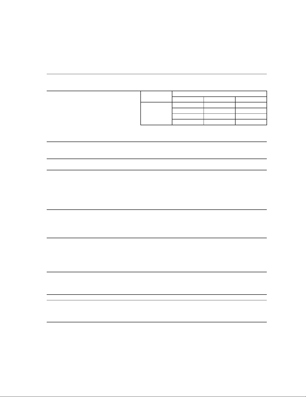
[a] KM-201BAH
AC SUPPLY VOLTAGE 115/60/1
AMPERAGE 6.1 A ( 5 Min. Freeze AT 104°F / WT 80°F)
MAXIMUM FUSE SIZE N/A
APPROXIMATE ICE PRODUCTION Ambient WATER TEMP. (°F)
PER 24 HR. Temp.(°F) 50 70 90
lbs./day ( kg/day ) 70 *201 (91) 190 (86) 176 (80)
Reference without *marks 80 193 (88) 177 (80) 162 (73)
90 190 (86) *165 (75) 150 (68)
100 187 (85) 161 (73) *136 (62)
SHAPE OF ICE Crescent Cube
ICE PRODUCTION PER CYCLE 4.0lbs. (1.82 kg) 182pcs.
APPROXIMATE STORAGE CAPACITY 80 lbs(36Kg).
ELECTRIC & WATER CONSUMPTION 90/70°F 70/50°F
ELECTRIC W (kWH/100 lbs.) 510(7.5) 490(5.8)
WATER gal./24HR (gal./100 lbs.) 36(22.0) 72(35.6)
CEC/CEE TIER LEVEL 3
ENERGY STAR Yes
EXTERIOR DIMENSIONS (WxDxH) 24" x 28" x 39" (612 x 712 x 990 mm)
Including 6" legs
EXTERIOR FINISH Stainless Steel, Galvanized Steel (Rear)
WEIGHT Net 137 lbs. (62 kg), Shipping 165 lbs. (75 kg)
CONNECTIONS - ELECTRIC Cord Connection
- WATER SUPPLY Inlet 1/2" FPT
- DRAIN Outlet 3/4" FPT
CUBE CONTROL SYSTEM Float Switch
HARVESTING CONTROL SYSTEM Hot Gas and Water, Thermistor and Timer
ICE MAKING WATER CONTROL Timer Controlled. Overflow Pipe
COOLING WATER CONTROL N/A
BIN CONTROL SYSTEM Mechanical Level Switch with Delay
COMPRESSOR Hermetic, Model NF7CLX
CONDENSER Air-Cooled, Fin and tube type
EVAPORATOR Vertical type, Stainless Steel and Copper
REFRIGERANT CONTROL Thermostatic Expansion Valve
REFRIGERANT CHARGE R-404A, 12 oz. (340g)
DESIGN PRESSURE High 467PSIG, Low 230PSIG
P.C. BOARD CIRCUIT PROTECTION High Voltage Cut-out ( Internal )
COMPRESSOR PROTECTION Auto-reset Overload Protector ( Internal )
REFRIGERANT CIRCUIT PROTECTION Auto-reset High Pressure Control Switch
LOW WATER PROTECTION Float Switch
ACCESSORIES -SUPPLIED Ice Scoop, 6" leg 4 pcs
OPERATING CONDITIONS VOLTAGE RANGE 104 - 127 V
AMBIENT TEMP. 45 -100° F
WATER SUPPLY TEMP. 45 - 90° F
WATER SUPPLY PRESSURE 10 - 113 PSIG
We reserve the right to make changes in specifications and design without prior notice.
1
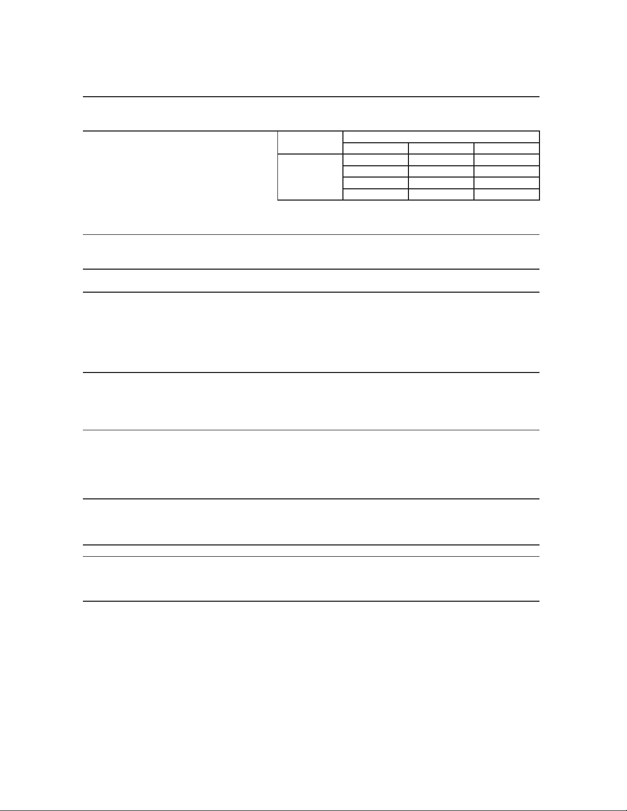
[b] KM-260BAH
AC SUPPLY VOLTAGE 115/60/1
AMPERAGE 7.6 A ( 5 Min. Freeze AT 104°F / WT 80°F)
MAXIMUM FUSE SIZE N/A
APPROXIMATE ICE PRODUCTION Ambient WATER TEMP. (°F)
PER 24 HR. Temp.(°F) 50 70 90
lbs./day ( kg/day ) 70 *263 (119) 247 (112) 227 (103)
Reference without *marks 80 251 (114) 226 (102) 207 (94)
90 247 (112) *208 (94) 189 (86)
100 244 (111) 203 (92) *171 (78)
SHAPE OF ICE Crescent Cube
ICE PRODUCTION PER CYCLE 5.0.lbs. (2.26kg) 238 pcs.
APPROXIMATE STORAGE CAPACITY 100 lbs(45Kg).
ELECTRIC & WATER CONSUMPTION 90/70°F 70/50°F
ELECTRIC W (kWH/100 lbs.) 620(7.1) 590(5.4)
WATER gal./24HR (gal./100 lbs.) 42(20.1) 78(29.7)
CEC/CEE TIER LEVEL 3
ENERGY STAR Yes
EXTERIOR DIMENSIONS (WxDxH) 30" x 28" x 39" (762 x 712 x 990 mm)
Including 6" legs
EXTERIOR FINISH Stainless Steel, Galvanized Steel (Rear)
WEIGHT Net 154 lbs. (70 kg), Shipping 187 lbs. (85 kg)
CONNECTIONS - ELECTRIC Cord Connection
- WATER SUPPLY Inlet 1/2" FPT
- DRAIN Outlet 3/4" FPT
CUBE CONTROL SYSTEM Float Switch
HARVESTING CONTROL SYSTEM Hot Gas and Water, Thermistor and Timer
ICE MAKING WATER CONTROL Timer Controlled. Overflow Pipe
COOLING WATER CONTROL N/A
BIN CONTROL SYSTEM Mechanical Level Switch with Delay
COMPRESSOR Hermetic, Model SC10CL
CONDENSER Air-Cooled, Fin and tube type
EVAPORATOR Vertical type, Stainless Steel and Copper
REFRIGERANT CONTROL Thermostatic Expansion Valve
REFRIGERANT CHARGE R-404A 12.7oz (360g)
DESIGN PRESSURE High 467PSIG, Low 230PSIG
P.C. BOARD CIRCUIT PROTECTION High Voltage Cut-out ( Internal )
COMPRESSOR PROTECTION Auto-reset Overload Protector ( Internal )
REFRIGERANT CIRCUIT PROTECTION Auto-reset High Pressure Control Switch
LOW WATER PROTECTION Float Switch
ACCESSORIES -SUPPLIED Ice Scoop, 6" leg 4 pcs
OPERATING CONDITIONS VOLTAGE RANGE 104 - 127 V
AMBIENT TEMP. 45 -100° F
WATER SUPPLY TEMP. 45 - 90° F
WATER SUPPLY PRESSURE 10 - 113 PSIG
We reserve the right to make changes in specifications and design without prior notice.
2
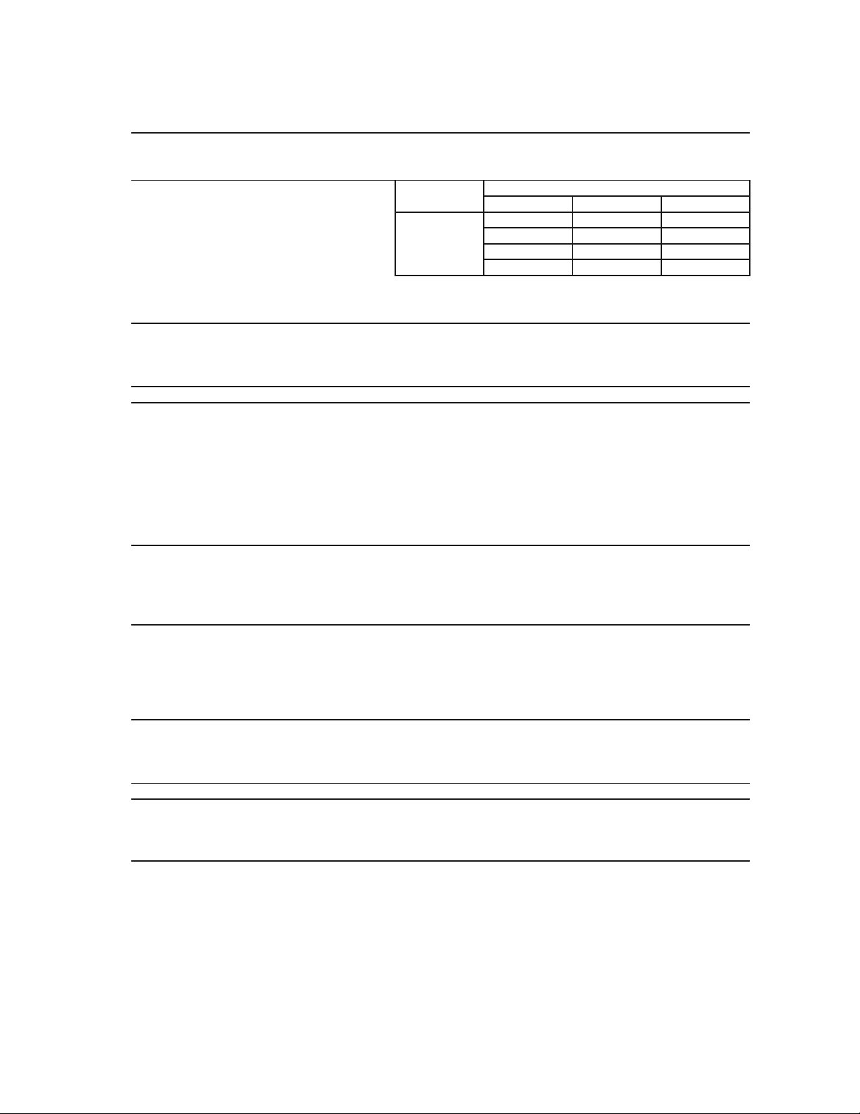
[c] KM-201BWH
AC SUPPLY VOLTAGE 115/60/1
AMPERAGE 5.5 A ( 5 Min. Freeze AT 104°F / WT 80°F)
MAXIMUM FUSE SIZE N/A
APPROXIMATE ICE PRODUCTION Ambient WATER TEMP. (°F)
PER 24 HR. Temp.(°F) 50 70 90
lbs./day ( kg/day ) 70 *215 (98) 207 (94) 192 (87)
Reference without *marks 80 209 (95) 195 (89) 180 (82)
90 207 (94) *186 (84) 171 (78)
100 203 (92) 182 (83) *157 (71)
SHAPE OF ICE Crescent Cube
ICE PRODUCTION PER CYCLE 4.0lbs. (1.82 kg) 182pcs.
APPROXIMATE STORAGE CAPACITY 80 lbs(36Kg).
ELECTRIC & WATER CONSUMPTION 90/70°F 70/50°F
ELECTRIC W (kWH/100 lbs.) 460(5.93) 460(5.08)
WATER gal./24HR (gal./100 lbs.) 45(24.0) 55(25.6)
COND.WATER gal./24HR (gal./100 lbs) 226(141.3) 119(55.6)
CEC/CEE TIER LEVEL 3
EXTERIOR DIMENSIONS (WxDxH) 24" x 28" x 39" (612 x 712 x 990 mm)
Including 6" legs
EXTERIOR FINISH Stainless Steel, Galvanized Steel (Rear)
WEIGHT Net 137 lbs. (62 kg), Shipping 165 lbs. (75 kg)
CONNECTIONS - ELECTRIC Cord Connection
- WATER SUPPLY Inlet 1/2" FPT
- DRAIN Outlet 3/4" FPT
CONDENSER WATER Inlet 1/2" FPT
Outlet 1/2" FPT
CUBE CONTROL SYSTEM Float Switch
HARVESTING CONTROL SYSTEM Hot Gas and Water, Thermistor and Timer
ICE MAKING WATER CONTROL Timer Controlled. Overflow Pipe
COOLING WATER CONTROL N/A
BIN CONTROL SYSTEM Mechanical Level Switch with Delay
COMPRESSOR Hermetic, Model NF7CLX
CONDENSER Water-Cooled, Tube type
EVAPORATOR Vertical type, Stainless Steel and Copper
REFRIGERANT CONTROL Thermostatic Expansion Valve
REFRIGERANT CHARGE R-404A, 11 oz. (310g)
DESIGN PRESSURE High 467PSIG, Low 230PSIG
P.C. BOARD CIRCUIT PROTECTION High Voltage Cut-out ( Internal )
COMPRESSOR PROTECTION Auto-reset Overload Protector ( Internal )
REFRIGERANT CIRCUIT PROTECTION Auto-reset High Pressure Control Switch
LOW WATER PROTECTION Float Switch
ACCESSORIES -SUPPLIED Ice Scoop, 6" leg 4 pcs
OPERATING CONDITIONS VOLTAGE RANGE 104 - 127 V
AMBIENT TEMP. 45 -100° F
WATER SUPPLY TEMP. 45 - 90° F
WATER SUPPLY PRESSURE 10 - 113 PSIG
We reserve the right to make changes in specifications and design without prior notice.
3
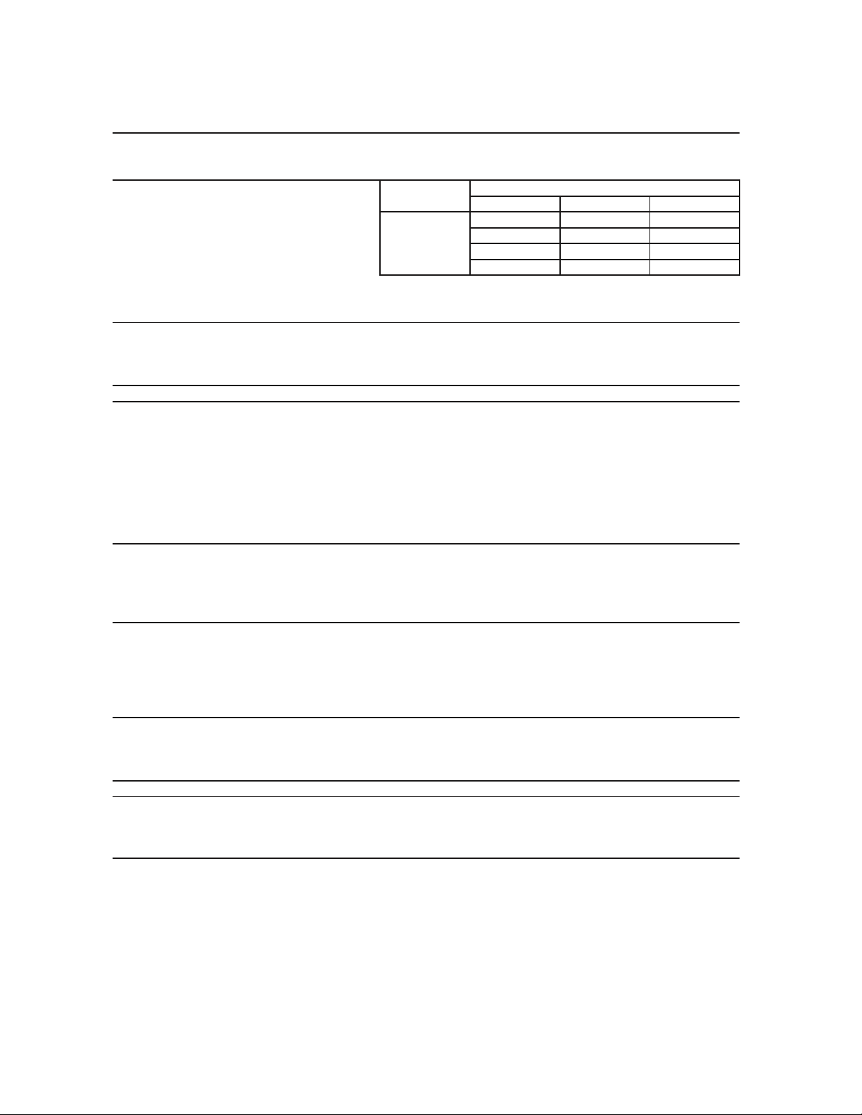
[d] KM-260BWH
AC SUPPLY VOLTAGE 115/60/1
AMPERAGE 7.5 A ( 5 Min. Freeze AT 104°F / WT 80°F)
MAXIMUM FUSE SIZE N/A
APPROXIMATE ICE PRODUCTION Ambient WATER TEMP. (°F)
PER 24 HR. Temp.(°F) 50 70 90
lbs./day ( kg/day ) 70 *268 (122) 259 (117) 242 (110)
Reference without *marks 80 261 (118) 247 (112) 228 (103)
90 259 (117) *237 (108) 218 (99)
100 254 (115) 233 (106) *201 (91)
SHAPE OF ICE Crescent Cube
ICE PRODUCTION PER CYCLE 5.0.lbs. (2.26kg) 238 pcs.
APPROXIMATE STORAGE CAPACITY 100 lbs(45Kg).
ELECTRIC & WATER CONSUMPTION 90/70°F 70/50°F
ELECTRIC W (kWH/100 lbs.) 630(6.37) 620(5.59)
WATER gal./24HR (gal./100 lbs.) 62(26.3) 77(28.7)
COND.WATER gal./24HR (gal./100 lbs) 285(120.6) 151(56.2)
CEC/CEE TIER LEVEL 3
EXTERIOR DIMENSIONS (WxDxH) 30" x 28" x 39" (762 x 712 x 990 mm)
Including 6" legs
EXTERIOR FINISH Stainless Steel, Galvanized Steel (Rear)
WEIGHT Net 154 lbs. (70 kg), Shipping 187 lbs. (85 kg)
CONNECTIONS - ELECTRIC Cord Connection
- WATER SUPPLY Inlet 1/2" FPT
- DRAIN Outlet 3/4" FPT
CONDENSER WATER Inlet 1/2" FPT
Outlet 1/2" FPT
CUBE CONTROL SYSTEM Float Switch
HARVESTING CONTROL SYSTEM Hot Gas and Water, Thermistor and Timer
ICE MAKING WATER CONTROL Timer Controlled. Overflow Pipe
COOLING WATER CONTROL N/A
BIN CONTROL SYSTEM Mechanical Level Switch with Delay
COMPRESSOR Hermetic, Model SC10CL
CONDENSER Water-Cooled, Tube type
EVAPORATOR Vertical type, Stainless Steel and Copper
REFRIGERANT CONTROL Thermostatic Expansion Valve
REFRIGERANT CHARGE R-404A 13.8oz (390g)
DESIGN PRESSURE High 467PSIG, Low 230PSIG
P.C. BOARD CIRCUIT PROTECTION High Voltage Cut-out ( Internal )
COMPRESSOR PROTECTION Auto-reset Overload Protector ( Internal )
REFRIGERANT CIRCUIT PROTECTION Auto-reset High Pressure Control Switch
LOW WATER PROTECTION Float Switch
ACCESSORIES -SUPPLIED Ice Scoop, 6" leg 4 pcs
OPERATING CONDITIONS VOLTAGE RANGE 104 - 127 V
AMBIENT TEMP. 45 -100° F
WATER SUPPLY TEMP. 45 - 90° F
WATER SUPPLY PRESSURE 10 - 113 PSIG
We reserve the right to make changes in specifications and design without prior notice.
4
II. GENERAL INFORMATION
1. CONSTRUCTION
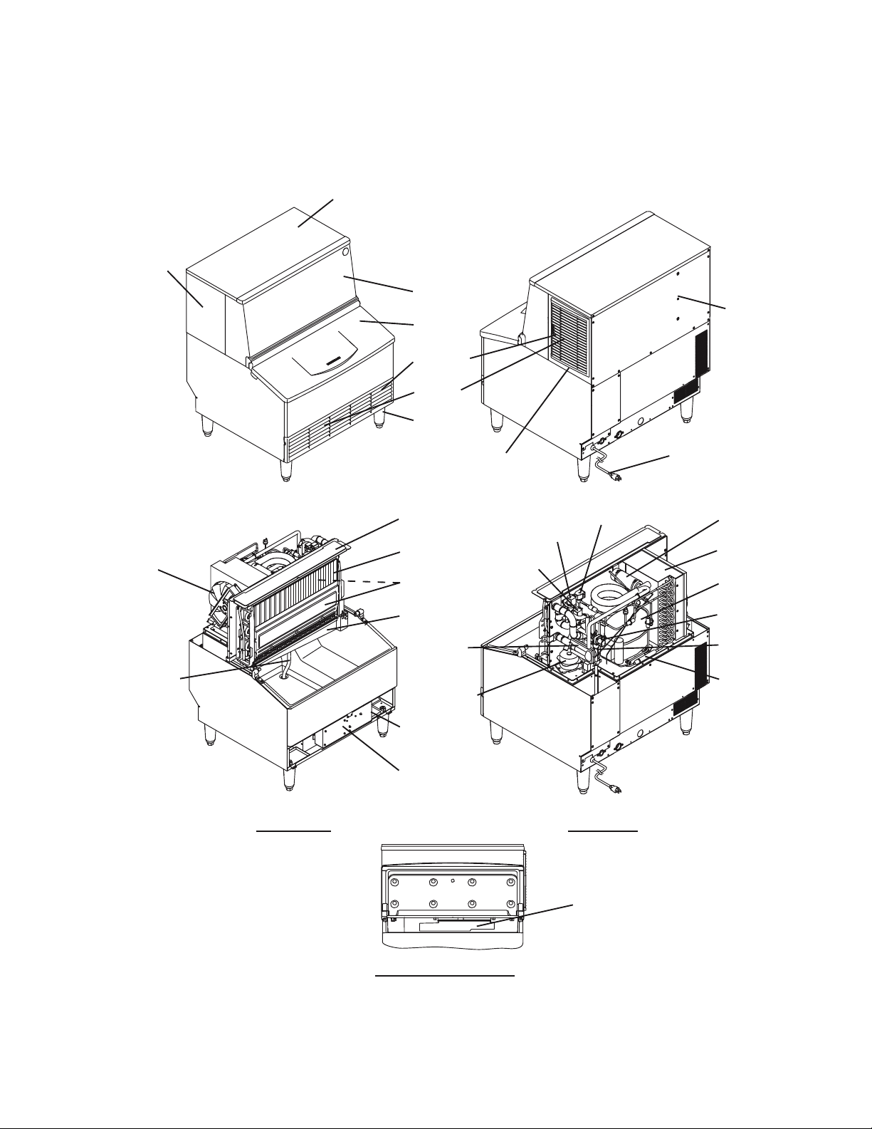
[a] KM-201BAH, KM-260BAH
Top Panel
Side Panel (L)
Front Cover
Rear Panel
Door
Air Filter
Louver
Leg
Side Panel (R) Power Supply Cord
Top Cover Hot Gas Valve Thermistor
Drain Valve
Evaporator Condenser
Fan Motor Cleaning Valve
Separator Compressor
Water Tank Water Valve
Expansion Float Switch
Valve
Overflow Pipe Drier
Pump Motor
Control Switch
Service Switch
Control Box
Front View Rear View
Bin Control Switch
With Tank Removed
5
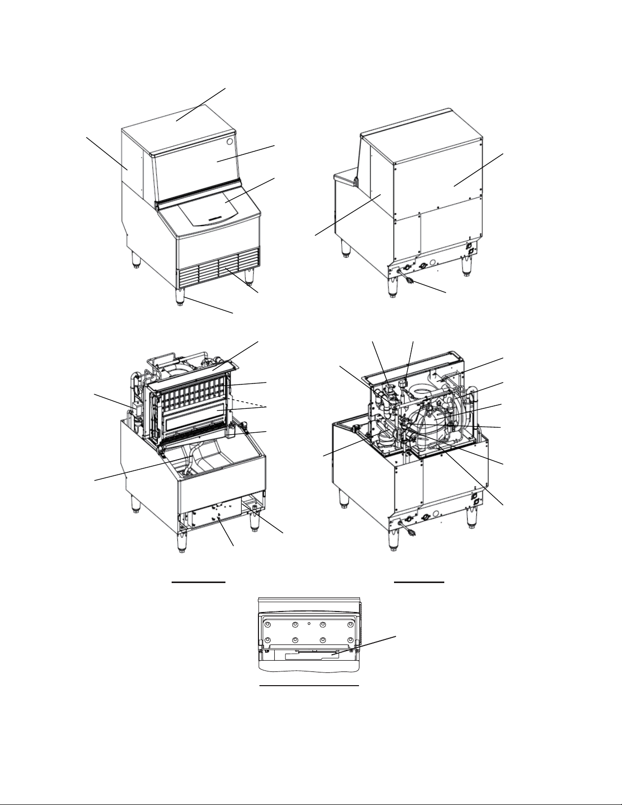
[b] KM-201BWH
Top Panel
Side Panel (L)
Front Cover
Rear Panel
Door
Side Panel (R)
Louver Power Supply Cord
Leg
Top Cover Drain Valve Hot Gas Valve
Cleaning Valve Thermistor
Water Regulator Evaporator Condenser
Separator Compressor
Water Tank Water Valve
Expansion
Valve Float Switch
Overflow Pipe
Drier
Control Switch
Service Switch
Control Box
Front View Rear View
Bin Control Switch
With Tank Removed
6
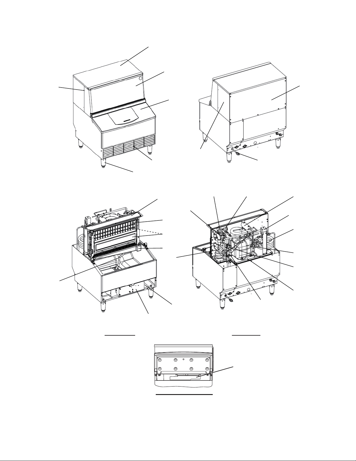
[c] KM-260BWH
Top Panel
Front Cover
Side Panel (L) Rear Panel
Door
Side Panel (R)
Louver Power Supply Cord
Leg
Top Cover Drain Valve Hot Gas Valve Thermistor
Cleaning Valve
Water Regulator
Evaporator
Condenser
Separator
Water Tank
Compressor
Expansion
Valve Water Valve
Overflow Pipe
Drier
Control Switch Float Switch
Service Switch
Control Box
Front View Rear View
Bin Control Switch
With Tank Removed
7
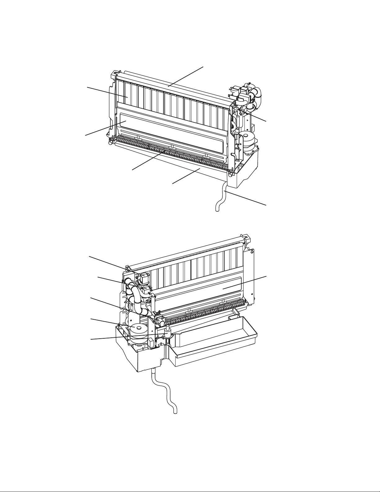
[d] ICEMAKING COMPARTMENT
Spray Tube
Evaporator
Water Supply Pipe
Separator
Cube Guide
Water Tank
Overflow Pipe
Drain Valve
Cleaning Valve Separator
Water Valve
Pump Motor
Float Switch
8

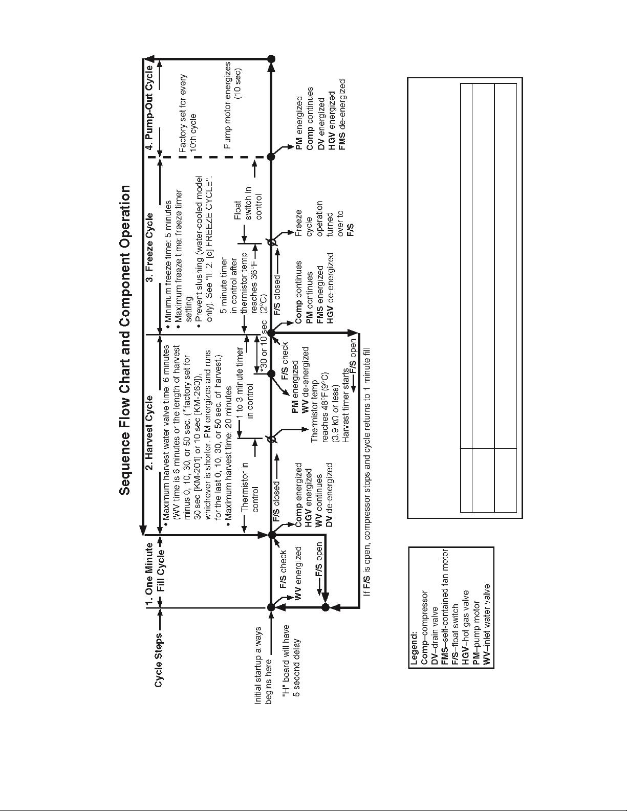
2. SEQUENCE OF OPERATION
The steps in the sequence are as outlined below. When power is supplied, a 5 second
delay occurs at startup. Note that the order of the LEDs from the outer edge of the board
is 5, 6, 8, 9, 4, 7.
[a] ONE MINUTE FILL CYCLE
LED 8 is on. WV opens and the fill period begins. After 1 minute, the board checks for
a closed F/S. If F/S is closed, the harvest cycle begins. If not, WV will remain energized
through additional 1 minute cycles until water enters the sump and F/S closes. This
serves as a low water safety to protect the pump motor.
[b] INITIAL HARVEST CYCLE
LEDs 5, 6, and 8 are on. WV remains open, Comp energizes, HGV opens, and harvest
begins. As the evaporator warms, the thermistor located on the suction line checks for a
48°F (9°C) temperature. When 48°F (9°C) is reached, a 3.9 kΩ signal turns the harvest
over to the adjustable harvest timer which is factory set for normal conditions. The timer
has settings of 60, 90, 120, and 180 seconds (S1 dip switch 1 & 2). When the harvest
timer completes its count down, the harvest cycle is complete and the freeze cycle
starts. The minimum total time allowed by the board for a complete harvest cycle is 2
minutes. WV is open during harvest for a maximum of 6 minutes or the length of harvest
minus 0, 10, 30, or 50 seconds (adjustable by S1 dip switch 7 & 8), whichever is shorter.
LED 8 goes off when WV closes. PM energizes and runs for the last 0, 10, 30, or 50
seconds of harvest depending on S1 dip switch 7 & 8 setting. LED 7 comes on when
PM energizes. At the end of harvest, the control board checks the position of F/S and
proceeds to the freeze cycle if it is closed or calls for a 1-minute fill if it is open.
[c] FREEZE CYCLE
LEDs 5 & 7 are on. Comp continues to run, PM and FMS energize, HGV closes and the
freeze cycle starts. For the first 5 minutes after the thermistor temperature reaches 36°
F (2°C), the control board will not accept a signal from F/S. This minimum freeze period
acts as a short cycle protection. At the end of this period, F/S assumes control. As the
evaporator cools, the thermistor located on the suction line checks for a 50°F (10°C)
temperature. When 50°F (10°C) is reached, the pump motor stops for 10 seconds. Then,
the pump motor repeats a 50 second ON and 10 second OFF cycle. After the thermistor
reaches 34°F (1°C), the pump motor stops for 10 seconds, runs for 50 seconds, stops
again for 10 seconds, and runs until the end of freeze cycle. This is to prevent slushing
(water-cooled model only). As ice builds on the evaporator the water level in the sump
lowers. The freeze continues until F/S opens and terminates ice production.
[d] PUMP-OUT CYCLE
LEDs 4, 5, 6, and 7 are on. Comp continues to run, HGV opens, FMS de-energizes, and
PM energizes. DV opens for 10 seconds to drain out the water tank. Pump-out cycle
9

always occurs on the 2nd harvest after startup. Then, depending on the control board
setting, pump-out cycle occurs every cycle, or every 2nd, 5th, or 10th cycle (S1 dip
switch 5 & 6).
[e] NORMAL HARVEST CYCLE
LEDs 5, 6, and 8 are on. Comp continues to run, HGV remains open and WV opens.
As the evaporator warms, the thermistor reaches 48°F (9°C). The control board then
receives the thermistor's 3.9 kΩ signal and starts the harvest timer. WV is open during
harvest for a maximum of 6 minutes or the length of harvest minus 0, 10, 30, or 50
seconds (adjustable by S1 dip switch 7 & 8), whichever is shorter. LED 8 goes off when
WV closes. PM energizes and runs for the last 0, 10, 30, or 50 seconds of harvest
depending on S1 dip switch 7 & 8 setting. LED 7 comes on when PM energizes. At the
end of harvest, the control board checks the position of F/S and proceeds to the freeze
cycle if it is closed or calls for a 1-minute fill if it is open.
The unit continues to cycle through [c], [d], and [e] sequence until the bin control is
activated and shuts the unit down. When the bin control is activated, the “POWER OK”
LED flashes.
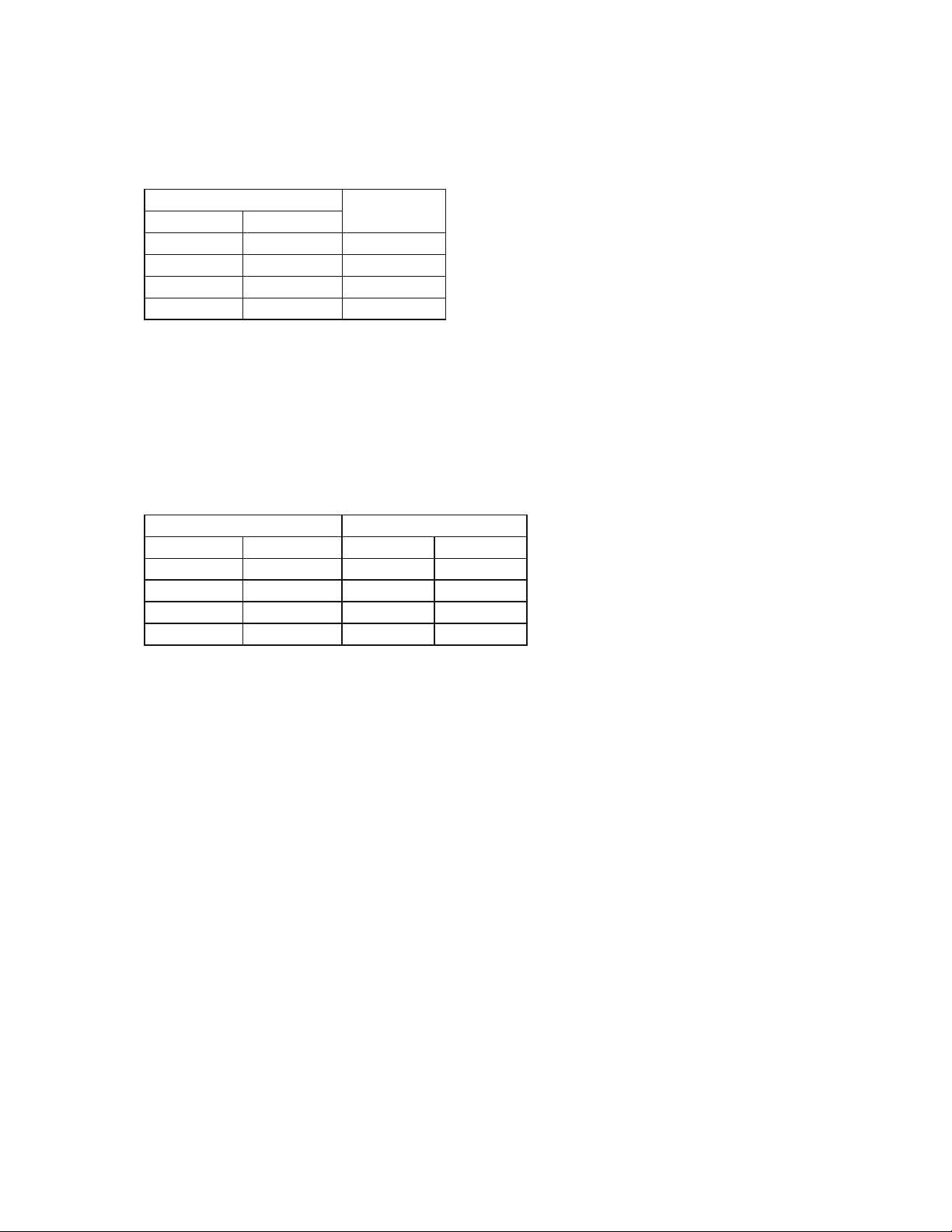
[f] SHUTDOWN
When BC is activated (BC open), the “POWER OK” LED flashes. There is a delay
before the shutdown sequence begins. The delay varies depending on the cycle the
icemaker is in at the time of activation. For details, see the table below.
Cycle at Bin Control Activation Delay Before Shutdown Sequence Begins
Fill Cycle 15 seconds
Harvest Cycle 15 seconds after the next freeze cycle starts
Freeze Cycle 15 seconds if BC is activated between the beginning of
freeze and termination of the 5-minute short cycle protection
timer (timer starts when the thermistor temperature drops to
36°F (2°C) (5.5 kΩ or more)). After this time, the unit will not
shut down until the next harvest cycle is complete.
After the delay, all components de-energize. DV energizes after 2 seconds. PM
energizes after 2 seconds. PM takes water from the tank and forces it through DV and
down the drain. The water tank drains for a maximum of 5 minutes or until F/S opens.
DV and PM (if applicable) then de-energize. When BC closes again calling for ice, the
unit starts at the 1-minute fill cycle. There is a 90-second minimum off time before the
icemaker can restart.
Legend: BC–bin control; Comp–compressor; DV–drain valve; FMS–self-contained fan
motor; F/S–float switch; HGV–hot gas valve; PM–pump motor; WV–inlet water
valve
10
11
and sanitizer over both the insde and outside surfaces of the evaporator.
extended periods of time over the outside surface of the evaporator.
DRAIN Power is supplied to the pump and drain valve. This drains the water tank.
CIRCULATE Power is supplied to the pump only. This operation can be used to circulate cleaner for
Components Energized when the Control Switch is in the “SERVICE” Position
When in the “SERVICE” position, the control switch supplies power to the service switch and the machine
is in service mode. The service switch has three positions: “DRAIN”, “CIRCULATE”, and “WASH”. See the
information below for details of each function.
WASH Power is supplied to the pump and cleaning valve. This operation is used to circulate cleaner

3. CONTROL BOARD
* A HOSHIZAKI exclusive solid-state control is employed in crescent cubers.
* All models are pretested and factory-adjusted.
CAUTION
1. Fragile, handle very carefully.
2. A control board contains integrated circuits, which are susceptible to
failure due to static discharge. It is especially important to touch the
metal part of the unit before handling or replacing the board.
3. Do not touch the electronic devices on the board or the back of the
board to prevent damage to the board.
4. Do not change wiring and connections.
5. Always replace the whole board assembly if it goes bad.
6. Do not short out the power supply to test for voltage.
12
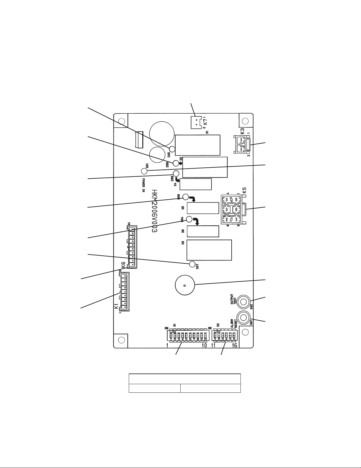
[a] CONTROL BOARD LAYOUT
r3FMBZ-&%T
JOEJDBUFXIJDI
SFMBZTBSFFOFSHJ[FE
BTMJTUFECFMPX
r-&%93FMBZ
$PNQSFTTPS$PNQ
'BO.PUPS3FNPUF
'.3
r-&%93FMBZ
)PU(BT7BMWF)(7
'BO.PUPS'.
(FM off when LED on)
-JRVJE-JOF7BMWF--7
'.BOE--7PGGXIFO
-&%PO
r-&%93FMBZ
*OMFU8BUFS7BMWF87
87POVOJUTXJUI
JOMFUXBUFSWBMWFT
r-&%93FMBZ
*OMFU8BUFS7BMWF
87POVOJUTXJUI
JOMFUXBUFSWBMWFT
r-&%93FMBZ
%SBJO7BMWF%7
r-&%93FMBZ
1VNQ.PUPS1.
)$POUSPM#PBSE
r,$POOFDUPS
5SBOTGPSNFS
r,$POOFDUPS
Power Relay
.BHOFUJD$POUBDUPS
r108&30,-&%
-JHIUTXIFOQPXFSJT
TVQQMJFEUPUIFCPBSE
'MBTIFTXIFOCJO
DPOUSPMJTBDUJWBUFE
r,$POOFDUPS
1JOT
'BO.PUPS'.
-JRVJE-JOF7BMWF--7
)PU(BT7BMWF
1VNQ.PUPS
*OMFU8BUFS7BMWF
0QFO
%SBJO7BMWF
r,$POOFDUPS
0QFO
r,$POOFDUPS
1JOT
'MPBU4XJUDI
0QFO
#JO$POUSPM
5IFSNJTUPS
0QFO
r4%JQ4XJUDI
r4%JQ4XJUDI
"H" Control Board
Part Number P00013-02
13
r"MBSN#V[[FS
r0651655&45#VUUPO
VTFEUPUFTUSFMBZTPO
DPOUSPMCPBSE
r"-"3.3&4&5#VUUPO

[b] FEATURES
a) Maximum Water Supply Period - 6 minutes
The inlet water valve will be open during harvest for 6 minutes or the length of harvest
minus 0, 10, 30, or 50 seconds (adjustable by S1 dip switch 7 & 8), whichever is shorter.
b) Harvest Backup Timer and Freeze Timer
The harvest backup timer shuts down the icemaker if, for two cycles in a row, the
harvest cycle takes more than 20 minutes to complete. The control board will signal this
problem using 2 beeps every 3 seconds.
The freeze timer shuts down the icemaker if, for two cycles in a row, the freeze cycle
takes longer than the time specified to complete. The control board will signal this
problem using 3 beeps every 3 seconds. The time is factory set using S1 dip switch 9 &
10.
The alarm reset button on the control board must be pressed with power on to reset
either of these safeties.
c) High Temperature Safety
The temperature of the suction line in the refrigeration circuit is limited by the high
temperature safety. This protects the unit from excessively high temperatures. If the
evaporator temperature rises above 127°F (53°C) ± 7°F (4°C), the thermistor operates
the safety. This shuts down the circuit and the icemaker automatically stops.
The control board will signal this problem using 1 beep every 3 seconds. The alarm
reset button on the control board must be pressed with power on to reset the safety.
d) Low Water Safety
The control board checks the position of the float switch at the end of the initial one
minute water fill cycle and at the end of each harvest cycle.
If the float switch is in the up position (electrical circuit closed), the control board
changes to the next cycle. If the float switch is in the down position (electrical circuit
open), the control board changes to additional one minute water fill cycles until water
enters the sump and the float switch closes. When the float switch closes, the control
board changes to the next cycle. The unit will not start without adequate water in the
sump. This serves as a low water safety to protect the water pump.
For water-cooled model, if the condenser water supply is shut off, the unit is protected
by the high-pressure switch.
e) High Voltage and Low Voltage Cut-outs
The maximum and minimum allowable supply voltages of this icemaker are limited by
the high voltage and low voltage cut-outs.
If miswiring (especially on single phase 3 wire models) causes excessive voltage (147Vac
± 5% or more) on the control board, the high voltage cut-out shuts down the circuit in 3
14
seconds and the icemaker automatically stops. The control board will signal this problem
using 7 beeps every 3 seconds.
The icemaker also automatically stops in cases of insufficient voltage (92Vac ± 5% or
less). The control board will signal this problem using 6 beeps every 3 seconds.
When the proper supply voltage is resumed, the icemaker automatically starts running
again.
f) LED Lights and Audible Alarm Safeties
The control board includes LED indicator lights, audible alarm safeties, and an output
test feature. The “POWER OK” LED indicates control voltage and will remain on unless
a control voltage problem occurs. The “POWER OK” LED flashes continuously when the
bin is full and DV energizes for a maximum of 5 minutes to drain the water tank.
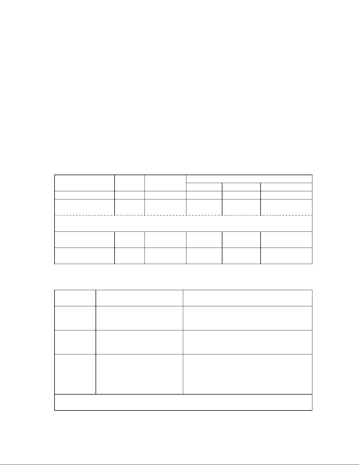
At startup, a 5 second delay occurs to stabilize the circuit. LEDs 4 through 8 energize
and sequence from initial startup as listed in the table below. Note that the order of the
LEDs from the outer edge of the board is 5, 6, 8, 9, 4, 7. For more information, see “2.
SEQUENCE OF OPERATION”.
Sequence Step LED
1 Minute Fill Cycle
Harvest Cycle 5, 6, 8
Last 0, 10, 30, or 50 seconds (adjustable by dip switch) of harvest, WV de-energizes
and PM energizes (LEDs 5, 6, and 7 are on)
Freeze Cycle 5, 7
Pump-Out Cycle 5, 6, 4, 7
8 WV 60 seconds
Energized
Components
WV, HGV,
Comp
Comp, PM,
FMS
Comp, HGV,
DV, PM
Min. Max. Avg.
2 minutes 20 minutes 3 to 5 minutes
5 minutes
10 seconds 20 seconds
Time LEDs are On
freeze timer
setting
25 to 30 minutes
factory default
setting
The built in safeties shut down the unit and have alarms as listed below.
No. of Beeps
(every 3 sec.)
1
High Evaporator Temp.
(temperature > 127
Type of Alarm Notes
Check for harvest problem (stuck HGV or
°F (53°C))
relay), hot water entering unit, stuck HM, or
shorted thermistor.
Harvest Backup Timer
2
(harvest > 20 min. for two
cycles in a row)
Freeze Timer
(freeze > specified setting for
3
two cycles in a row)
Timer is factory set using S1
Check for open thermistor, HGV not
opening, TXV leaking by, low charge,
inefficient Comp, or WRV leaking by.
Check for a float switch stuck closed (up),
WV leaking by, HGV leaking by, PM not
pumping, TXV not feeding properly, low
charge, or inefficient Comp.
dip switch 9 & 10
To reset the above safeties, press the
“ALARM RESET” button with the power supply
on.
15
6
7
Legend:
Low Voltage
(92Vac
± 5% or less)
High Voltage
(147Vac
± 5% or more)
Comp–compressor; DV–drain valve; FMS–self-contained fan motor; HGV–hot
“
POWER OK” LED will turn off if voltage
protection operates.
The control voltage safeties automaticlly
reset when voltage is corrected.
gas valve; PM–pump motor; TXV–thermostatic expansion valve; WRV–water
regulating valve; WV–inlet water valve
[c] CONTROLS AND ADJUSTMENTS
CAUTION
Dip switches are factory set. Failure to maintain factory settings may
adversely affect performance and warranty coverage.
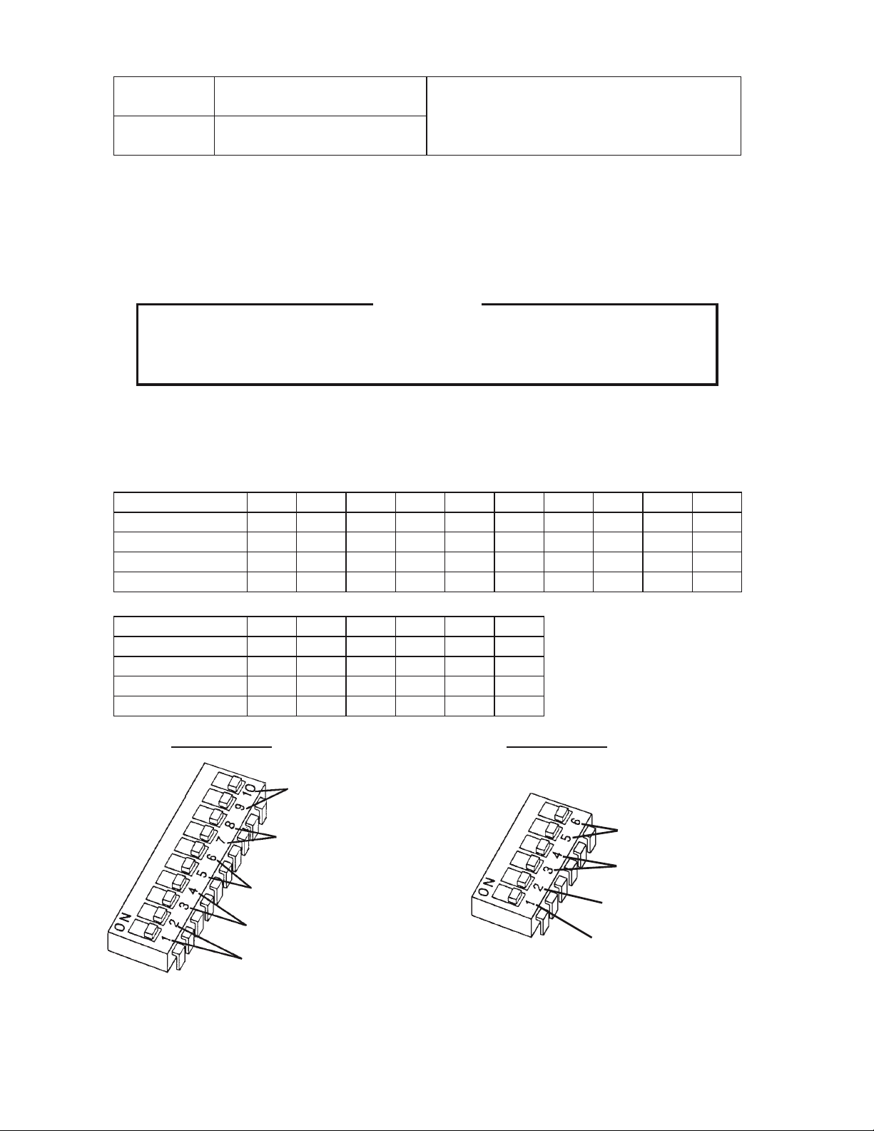
a) Default Dip Switch Settings
The dip switch is factory-adjusted to the following positions:
S1 Dip Switch No. 1 2 3 4 5 6 7 8 9 10
KM-201BAH
KM-260BAH
KM-201BWH
KM-260BWH
OFF OFF OFF OFF ON ON OFF ON ON OFF
OFF OFF OFF OFF ON ON ON OFF ON OFF
OFF OFF OFF OFF ON ON OFF ON ON OFF
ON OFF OFF OFF ON ON ON OFF OFF ON
S2 Dip Switch No. 1 2 3 4 5 6
KM-201BAH
KM-260BAH
KM-201BWH
KM-260BWH
ON OFF OFF OFF OFF ON
ON OFF OFF OFF OFF ON
ON OFF OFF OFF ON OFF
ON OFF OFF OFF ON OFF
Note:
S2 dip switch is
NOT adjustable.
S1 Dip Switch S2 Dip Switch
Freeze Timer (9 & 10)
Water Saver Timer (7 & 8)
Pump-Out Frequency Control
(5 & 6)
Pump-Out Timer (3 & 4)
Harvest Timer (1 & 2)
Anti-Slush Control (5 & 6)
Refill Counter (3 & 4)
Float Switch Selector (2)
Pump-Out/Drain Selector (1)
Fig. 1 Fig. 2
16
b) Harvest Timer (S1 dip switch 1 & 2)
Used for adjustment of the harvest timer. The harvest timer starts counting when the
thermistor reads a certain temperature at the evaporator outlet.
Dip Switch Setting
No. 1 No. 2
OFF OFF 60
ON OFF 90
OFF ON 120
ON ON 180
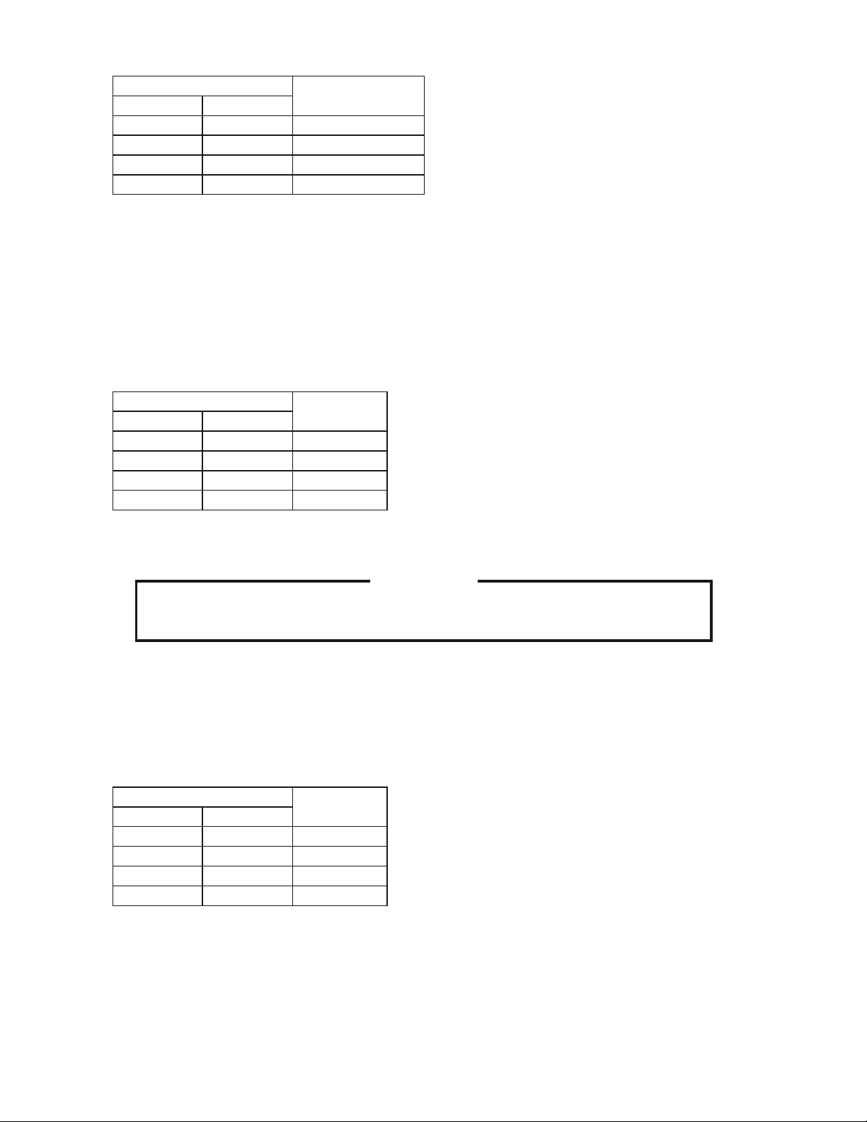
c) Pump-Out Timer (S1 dip switch 3 & 4)
Once every ten freeze cycles, the drain valve opens to drain the water tank for the time
determined by the pump-out timer. These switches also determine the time to delay
completion of a defrost cycle, i.e. the minimum defrost time.
Do not change this setting, or the unit will not operate properly or produce high quality
ice.
Dip Switch Setting Time (seconds)
No. 3 No. 4 T1 T2
OFF OFF 10 120
ON OFF 10 180
OFF ON 20 120
ON ON 20 180
Time
(seconds)
T1: Time to drain the water tank
T2: Harvest timer at pump-out
Pump-out cycle always occurs on the 2nd harvest after startup. Then, depending on the
pump-out frequency control setting (S1 dip switch 5 & 6), pump-out cycle occurs every
cycle, or every 2nd, 5th, or 10th cycle.
d) Pump-Out Frequency Control (S1 dip switch 5 & 6)
The water tank drains at the frequency set by the pump-out frequency control.
The pump-out frequency control is factory-adjusted to drain the water tank every 10
cycles, and no adjustment is required. However, where water quality is bad and the
icemaker needs a pump-out more often, the pump-out frequency can be adjusted as
shown in the table below.
17
Dip Switch Setting
No. 5 No. 6
OFF OFF every cycle
ON OFF every 2 cycles
OFF ON every 5 cycles
ON ON every 10 cycles
e) Harvest Pump Timer (S1 dip switch 7 & 8)
The harvest pump timer allows the water valve to close and the pump motor to circulate
water in the tank during the final part of harvest. The water valve is open during harvest
for a maximum of 6 minutes or the length of harvest minus 0, 10, 30, or 50 seconds
(determined by the harvest pump timer setting), whichever is shorter. When the water
valve closes, the pump motor energizes and runs for the time determined by the harvest
pump timer setting.
Frequency
Dip Switch Setting
No. 7 No. 8
OFF OFF 0
ON OFF 10
OFF ON 30
ON ON 50
f) Freeze Timer (S1 dip switch 9 & 10)
Time
(seconds)
CAUTION
Adjust to proper specification, or the unit may not operate correctly.
The freeze timer setting determines the maximum allowed freeze time to prevent
possible freeze-up issues. Upon termination of freeze timer, machine initiates the
harvest cycle. After 2 consecutive timer terminations, machine will shut down, possibly
indicating a problem.
The freeze timer is factory adjusted, and no adjustment is required.
Dip Switch Setting
No. 9 No. 10
ON OFF 50
OFF OFF 60
OFF ON 70
ON ON 100
Time
(minutes)
18
 Loading...