

Hoshizaki American, Inc. FH1-SSB, FH1-HD Service Manual

ISSUED:
REVISED:
MARCH 4, 1999
MARCH 13, 2003
HOSHIZAKI
REACH-INS
TempGuard
INSTRUCTION MANUAL
and SafeTemp
TM
TM

IMPORTANT
Only qualified service technicians should attempt to install, service or maintain this
unit. No installation, service or maintenance should be undertaken until the
technician has thoroughly read this Instruction Manual. Likewise, the owner/manager
should not proceed to operate the unit until the installer has instructed them on its
proper operation.
HOSHIZAKI provides this manual primarily to assist qualified service technicians in the
installation, maintenance and service of the unit.
Should the reader have any questions or concerns which have not been satisfactorily
addressed, please call or write to the HOSHIZAKI T echnical Support Department for
assistance.
HOSHIZAKI AMERICA, INC.
618 Highway 74 South
Peachtree City , GA 30269
Attn: HOSHIZAKI T echnical Support Department
Phone: 1-800-233-1940 T echnical Service
(770) 487-2331
Fax: (770) 487-3360
NOTE: T o expedite assistance, all correspondence/communication MUST include the following
information:
• Model Number
• Serial Number
• Complete and detailed explanation of the problem
2

• Please review this manual. It should be read carefully before the unit is installed and
operated. Only qualified service technicians should install, service and maintain the
unit. This manual should be made available to the technician prior to installation,
maintenance or service.
CONTENTS
• Keep this manual with the unit for later reference.
I . INSTALLA TION AND OPERA TING INSTRUCTIONS.............................. 13
1. CHECKS BEFORE INST ALLA TION............................................. 13
2. HOW TO REMOVE FRONT P ANEL ........................................... 14
[a] -SSB MODELS ...................................................................... 14
[b] -AAC MODELS ...................................................................... 14
3. LOCA TION .................................................................................. 15
4. SET UP ....................................................................................... 15
5. ELECTRICAL CONNECTION ...................................................... 16
6. OVERFLOW P AN ....................................................................... 16
7. DRAIN CONNECTION ................................................................. 16
8. ELECTRICALL Y HEA TED CONDENSATE P AN (RFH1-SSB-HD) 16
9. FINAL CHECK LIST.................................................................... 17
10. START-UP................................................................................... 18
[a] -SSB MODELS...................................................................... 18
[b] -AAC MODELS...................................................................... 18
1 1. ELECTRONIC CONTROL OPERATION (-SSB MODELS) ......... 19
12. ELECTRONIC CONTROL OPERATION (-AAC MODELS) ......... 27
13. DOOR REVERSING ................................................................... 29
PAGE
II. CLEANING AND MAINTENANCE INSTRUCTIONS .............................. 30
1. CLEANING................................................................................... 30
2. MAINTENANCE .......................................................................... 31
3
II. INST ALLA TION AND OPERA TING INSTRUCTIONS
1. CHECKS BEFORE INST ALLA TION
IMPORT ANT
Refer to the NAMEPLA TE for electrical specifications. The NAMEPLA TE is located
on the RIGHT side wall of the cabinet interior. We reserve the right to make specification and design changes without prior notice.
1) All tape, packing material and shipping cartons should be removed from the machine
prior to installation. The equipment should be inspected for any damage which may
have occurred during shipment. Concealed damage claims must be filed with the carrier.
a) Visually check that the refrigerant lines do not rub or touch other lines or surfaces
and that the fan blades turn freely.
b) Check that the compressor is snug on all mounting pads.
WARNING
The compressor bolts on FH3-SSB(-HD) models have been torqued down to
completely compress the springs during shipping.
Before turning the unit on, back the bolts off of the fastening points until no spring
compression is present. This will allow the compressor to float freely.
2) Remove all accessory containers before discarding the packing materials. Dispose of all
packing materials in a proper and environmentally responsible manner.
3) To remove the unit from the skid:
a) Move as close to the final location as possible.
b) Remove the four 5/8 in. bolts that secure the cabinet to the skid.
c) Block the cabinet securely, at a height of 8 inches (203 mm.) off the floor.
d) Attach the adjustable legs (or optional casters) to the bottom of the cabinet.
4
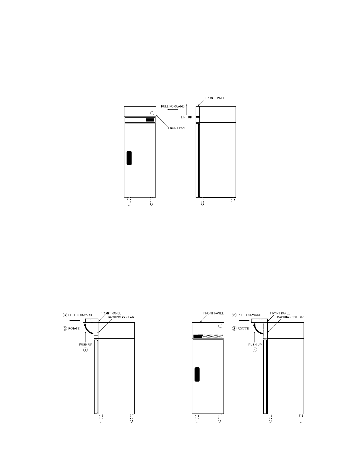
2. HOW TO REMOVE FRONT PANEL
[a] T empGuard MODELS with “Lift-Up” style Front Panel
• Lift the panel UP approximately 1/2 inch (13 mm.) and then pull it FORWARD.
[b] T empGuard with “Hinged” style Front Panel and all SafeTemp MODELS
1. Push the Front Panel UP approximately 1/2 inch (13 mm.) until it is disengaged from
the locking collars and stops.
2. Rotate the panel UP and AWAY from the face of the unit until it stops once more.
3. Pull the Front Panel FORWARD until the hinge assembly is in the LOCKED
position.
5
3. LOCA TION
CAUTION
This unit is not intended for outdoor installation. The air temperature should
be within a 45° F to 100° F range. Extended periods of operation at temperatures
exceeding these limitations may cause unsatisfactory results.
For best operating results:
• The machine should be on a flat, level and solid (firm) foundation.
• The unit should not be located in a corrosive environment.
• The air temperature range at the location should be between 45° F and 100° F.
• The unit should not be near ovens, grills or other high heat producing equipment.
• The unit should be a minimum of 4 inches (102 mm.) from all walls.
• If the unit is flush against a wall, a minimum of 10 inches (254 mm.) overhead clearance
for proper ventilation should be provided.
4. SET UP
1) Position the unit in the selected location. Level the unit in both the front-to-back and
side-to-side directions. The feet are provided with hex flats in order to facilitate
adjustment. Turn clockwise to lower each leg, and counterclockwise to raise each
leg.
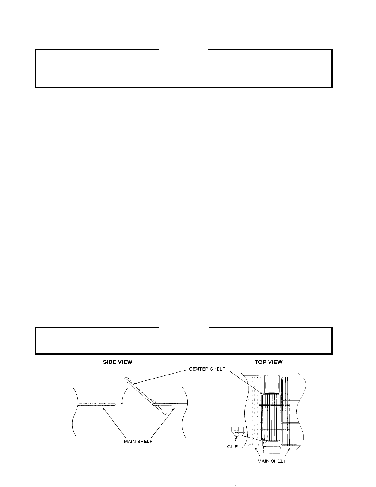
2) Install the optional shelves using the shelf support clips provided in the accessory pack.
Indexing holes are provided every five positions to assist you in locating the support
clips. Two and three section units may be equipped with center shelves which should
be installed after the main shelves are in place. The center shelf kit contains additional
clip(s) which support the center shelf when the main shelves on one side of the cabinet
are not aligned with the main shelves of the other side of the cabinet.* See the
diagrams below.
CAUTION
*Without this additional support, under adverse loading conditions, the shelf assembly
could tip.
6
5. ELECTRICAL CONNECTION
1) Cord-connected units should only be plugged into a 115 volt ±10%, 60 Hz. circuit with a
national and local electrical code approved, grounded wall receptacle. A separate
circuit with its own circuit breaker (HACR type) or fuse (LP-CC type) should be
provided. Refer to the NAMEPLATE for the proper electrical specifications.
2) Hardwired units should only be wired into the proper conduit, with its own circuit
breaker (HACR type) or fuse (LP-CC type). Refer to the NAMEPLATE for the proper
electrical specifications.
WARNING
Failure to use a proper breaker or fuse can result in tripped breaker, blown fuses or
damage to existing wiring.
TAB
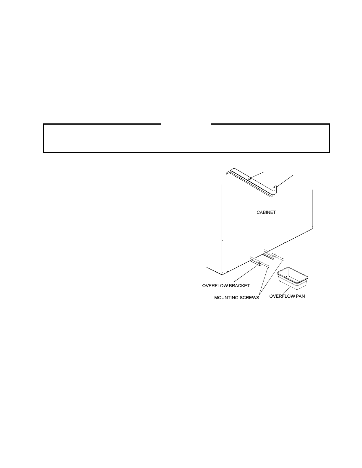
6 . OVERFLOW PAN (if applicable)
OVERFLOW
BRACKET
Note: For units with an
electrically heated
condensate pan, see section “8.”)
1) Assemble the overflow pan's brackets by
engaging the tab on the bracket through
the hole in the unit bottom and securing
with the four mounting screws provided.
2) Slide the plastic pan into place under the
vinyl hose on the back of cabinet.
7 . DRAIN CONNECTION (if applicable)
1) This unit is provided with an energy efficient automatic condensate water disposal
system and normally requires no drain connection.
2) High relative humidity and frequent door openings for long periods of time could cause
excessive condensate water to form.
3) If this occurs, condensate water will drain out through the overflow drain tube located
inside the back wall of the cabinet and into the Overflow Pan.
4) In the unlikely event that water is found in the Overflow Pan, call your HOSHIZAKI
Service Representative for assistance.
7
 Loading...