

Hoshizaki American, Inc. DCM-500BAH-OS, DCM-500BWH-OS Part Manual

Hoshizaki America, Inc.
Hoshizaki
Cubelet Icemaker/Dispenser
Models
DCM-500BAH-OS
“A Superior Degree
of Reliability”
www.hoshizaki.com
DCM-500BWH-OS
PARTS LIST
®
Number: 71212
Issued: 11-26-2002
Revised: 11-17-2010

CONTENTS
Auxiliary Codes ...................................................................................................................... 3
Note About Ordering Parts .................................................................................................... 3
Material Abbreviations ........................................................................................................... 4
A. Ice Dispenser Assembly .................................................................................................... 5
DCM-500BAH-OS ............................................................................................................. 5
DCM-500BWH-OS .......................................................................................................... 10
B. Refrigeration Circuit ......................................................................................................... 15
DCM-500BAH-OS ........................................................................................................... 15
DCM-500BWH-OS .......................................................................................................... 19
C. Icemaking Unit ................................................................................................................ 23
D. Water Circuit .................................................................................................................... 24
E. Control Box Assembly...................................................................................................... 28
F. Apron Panel Assembly ..................................................................................................... 33
G. Middle Front Frame Assembly ......................................................................................... 34
H. Shutter Assembly............................................................................................................. 35
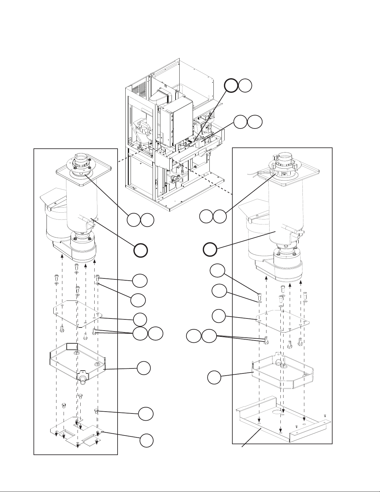
J. Gear Motor Assembly (Agitator) ....................................................................................... 37
K. Gear Motor Assembly (Dispense) .................................................................................... 38
L. Bin Assembly ................................................................................................................... 39
M. Frame Assembly ............................................................................................................. 40
N. Label Location ................................................................................................................. 42
P. Evaporator Assembly ...................................................................................................... 44
Q. Bin Top Assembly ............................................................................................................ 46
R. Accessories & Packaging ................................................................................................ 47
2

Auxiliary Codes
DCM-500BAH-OS
M-0 October 2002
N-0 December 2002
N-1 November 2003
P-0 December 2003
P-1 June 2004
Q-0 December 2004
Q-1 February 2005
R-0 December 2005
S-0 January 2007
S-1 November 2007
T-0 January 2008
T-0 (C) March 2008
T-0 (E) May 2008
T-1 October 2008
U-0 February 2009
U-1 August 2009
V-0 January 2010
V-2 May 2010
V-3 June 2010
V-4 October 2010
V-5 November 2010
DCM-500BWH-OS
N-0 December 2002
N-1 September 2003
P-0 March 2004
Q-0 January 2005
Q-1 October 2005
R-0 January 2006
S-0 January 2007
S-1 December 2007
T-0 January 2008
U-0 January 2009
U-1 October 2009
V-0 February 2010
V-2 May 2010
V-3 June 2010
V-4 September 2010
V-5 November 2010
A-0 January 2011
Auxiliary Code Breakdown
The auxiliary code is the rst two characters in the serial number. The rst character
indicates the year. Years progress or regress in alphabetical order. The series runs from
"A" through "V" and the letters "I" and "O" are skipped. The second character indicates
signicant part changes within a year. Base is "0" and this number advances for each
change. In cases where there is a letter in parentheses, this designates the month. This is
the last character in the serial number. The series runs from "(A)" through "(M)" and the
letter "(I)" is skipped. This designation is only included when identifying a parts change
within an auxiliary code.
Note About Ordering Parts
Most assemblies cannot be ordered as complete units; parts in the assemblies generally
must be ordered separately.
3

Material Abbreviations
ALUMINUM
AL = Aluminum
COPPER
CU = Copper
PLASTIC
ABS = Acrylonitrile -butadiene - styrene
AC = Polyacetal
EPP = Expanded Polypropylene
EVA = Ethylene vinyl acetate
PA = Polyamide = Nylon
PC = Polycarbonate
PE = Polyethylene
PES = Polyester
PETP = Polyethylene terephthalate = Tetlon
PP = Polypropylene
PS = Polystyrene
PTFE = Polytetrauoroethylene = Teon
PUR = Polyurethane
PVC = Polyvinyl chloride
RUBBER
EPDM = EP rubber
EPH = Epichlorohydrin
NBR = Nitrile butadiene rubber
NP = Neoprene
NR = Natural rubber
SI.R = Silicone rubber
SY.R = Synthetic rubber
VN = Vinyl Nitrile
STEEL
GS = Galvanized steel
PAS = Primed steel
PS = Plated steel
SS = Stainless steel
4
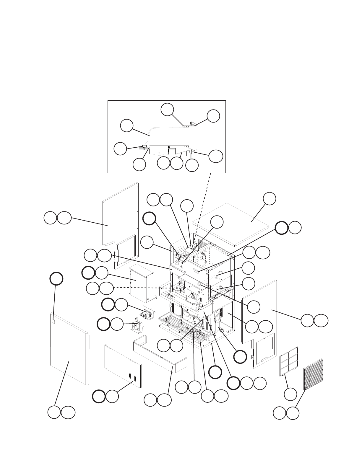
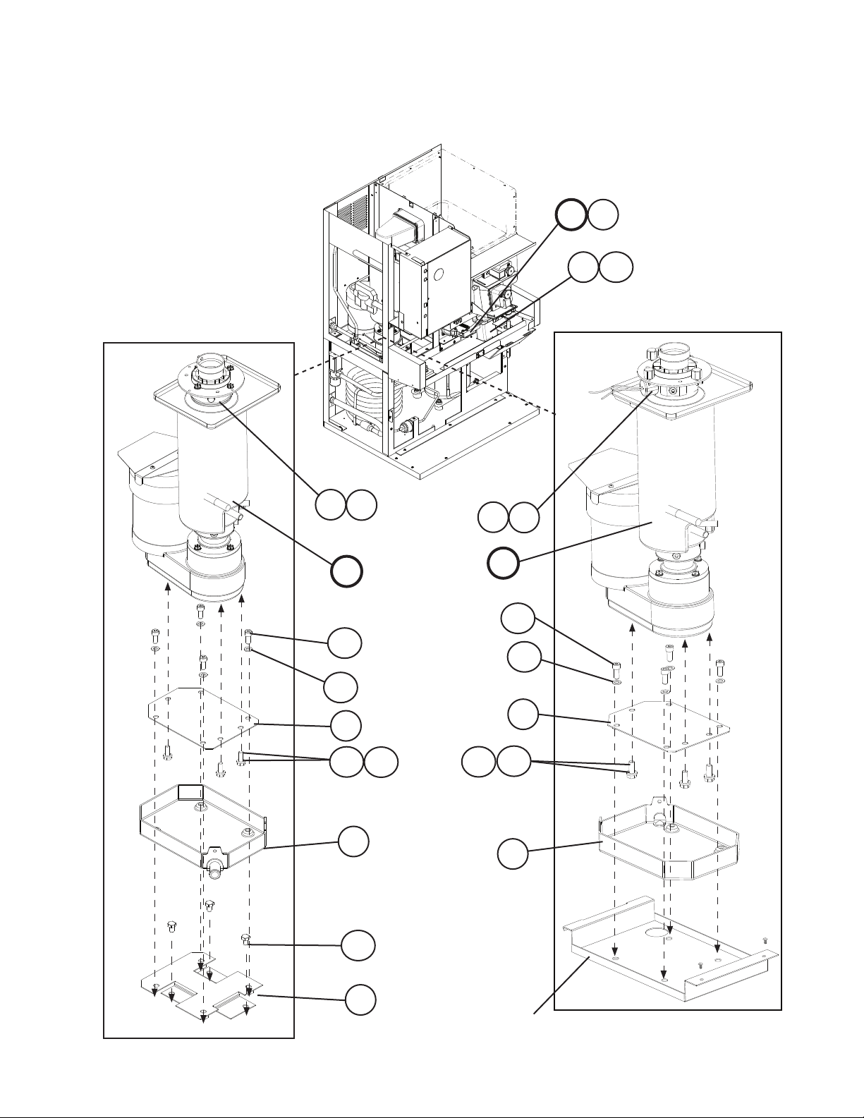
A. Ice Dispenser Assembly
1/2
DCM-500BAH-OS
M-0 to V-5
9
9a
6
5
10
5a
12
12a
13
20
N
20a
34
E
35
34a
E1
35a
K
J
K1
J1
D
33
11
14
18a
14a
24
L
L1
21
21a
7
8
32
4
18
23
22
2a
2
B
16
16a
F
F1
15
15a
M
G1
173
19
5
G
19a
G2
31
1a
1
A. Ice Dispenser Assembly
2/2
DCM-500BAH-OS
M-0 to V-5
H
25
H1
25a
S-1 to V-2
29
28b
28a
C
26
30
29
V-3 and later
30
C
28b
28a
26
26a
28
27a
27
26b
26b
26a
28
See "M. Frame Assembly," items 6 and 6a.
6

Title: A. Ice Dispenser Assembly Model: DCM-500BAH-OS
Required Number
M-0
Q-0
Index
No. Description
B Refrigeration Circuit 227494A02 1 1 1 1 1 1 -
C Icemaking Unit 3A0623A03 1 1 1 1 -
D Water Circuit 2A0395A02 1 1 1 1 -
E Control Box Assembly 2A2615A01 1 1 1 -
E1 Truss Head Screw 4×8 7C31-0408 3 3 3 3 3 3 3 3 -
FT Screw 4×8, SS 7F32-0408 4 4
F Apron Panel Assembly 3A2502A01 1 -
F1 Truss Head Screw 4×8, SS 7C32-0408 4 4 4 4 4 4 4 4 4 4
G Middle Front Frame Assembly 2A2603A01 1 1 1 1 1 -
G1 Taper Collar SS 4H0171-01 2 2 2 2 2 2 2 2 2 2
G2 Flat Head Screw 4×12, SS 7C22-0412 2 2 2 2 2 2 2 2 2 2
H Shutter Assembly 2A0410A01 1 1 1 1 1 1 1 1 1 1
H1 Truss Head Screw 4×8, SS 7C32-0408 2 2 2 2 2 2 2 -
FT Screw 7F32-0408 2 2 2
J Gear Motor Assembly (Agitator) 4A0620A01 1 1 1 1 1 1 1 1 1 1
J1 Thumbscrew 415949G12 2 2 2 2 2 2 2 2 2 2
K Gear Motor Assembly
(Dispense)
K1 Thumbscrew 415949G12 2 2 2 2 2 2 2 2 2 2
L Bin Assembly 2A0413A01 1 1 1 1 1 1 1 -
L1 Truss Head Screw 4×12, SS 7C32-0412 2 2 2 2 2 2 2 -
FT Screw 4×8, SS 7F32-0408 2 2 2
M Frame Assembly 2A0388A01 1 1 1 1 1 1 1 -
N Label Location 2A2604A01 1 1 1 1 -
Material or
Model Number Part Number
2A5916A01 1 1 1 2A5916A02 1
3A0623A04 1 1 1 1 1 1
2A0395A03 1 1 1 2A5455A01 1 1 1
2A2615A03 1 2A2615A05 1 2A2615A07 1 2A2615A09 1 2A5460A03 1 1 1
3A3618A01 1 1 1 1 1 1 1 1 1
2A2603A02 1 1 1 1 1
4A0622A01 1 1 1 1 1 1 1 1 1 1
2A0413A02 1 1 1
2A5324A02 1 1 1
2A2604A03 1 1 1 1 1 1
to
to
P-1
Q-1(G) Q-1(H)
R-0
to
S-0
S-1
U-1
to
to
U-0
V-0 V-2 V- 3 V-4 V-5
1 Louver 103121-03 2 2 2 2 2 2 2 2 2 2
1a Tapping Screw-Black 4×8 433954-01 2 2 2 2 2 2 2 2 2 2
2 Spout Cover 215773-01 1 1 1 1 1 1 1 1 1 1
2a Thumbscrew 415949G08 2 2 2 2 2 2 2 2 2 2
3 Cup Guide 326702-01 2 2 2 2
4 Bushing SR-30-1 420472-03 1 1 1 1 1 1 -
Cable Tie CV-150 8911-0150 1 1 1 1
2 2 2 2 2 2
7

Title: A. Ice Dispenser Assembly Model: DCM-500BAH-OS
Required Number
M-0
Q-0
Index
No. Description
5 Evaporator Bracket SS 3A0360-01 1 1 1 1 1 1 1 1 1 1
5a Hex Head Bolt w/Washer 5×10, SS 7B0230510 2 2 2 2 2 2 2 2 2 2
6 Packing 427151-02 1 1 1 1 1 1 1 1 1 1
7 Square Washer 433537-02 1 1 1 1 1 1 1 1 1 1
8 Ground Screw 433304-02 1 1 1 1 1 1 1 1 1 1
9 Spout 103329G01 1 1 1 1 1 1 1 1 1 1
9a Thumbscrew 415949G11 3 3 3 3 3 3 3 3 3 3
10 Packing (A) Spout 427195-01 1 1 1 1 1 1 1 1 1 1
11 Gasket 429758-01 2 2 2 2 2 2 2 2 2 2
12 Spout (B) 208807-01 1 1 1 1 1 1 1 1 1 1
12a Thumbscrew 415949G11 4 4 4 4 4 4 4 4 4 4
13 Packing (B) Spout 427196-01 1 1 1 1 1 1 1 1 1 1
14 Rear Panel GS 2A0405-01 1 1 1 1 1 1 1 -
14a Truss Head Screw 4×8, SS 7C32-0408 4 4 4 4 4 4 4 -
FT Screw 7F32-0408 4 4 4
15 Panel (Lo) SS 2A0699G01 1 1 1 1 1 1 1 1 1 1
15a FT Screw 4×8, SS 7F32-0408 6 6 6 6 6 6 6 6 6 6
16 Front Panel (A) 3A2853G01 1 1 1 1 1 -
16a T2 Screw 4×8, SS 7P32-0408 1 1 1 1 1 -
FT Screw 4×8, SS 7F32-0408 1 1 1 1 1
17 Grille 2A0827G01 1 1 1 1 1 1 1 1 1 1
18 Bin Cover 2A0880A02 1 1 1 1 1 1 1 1 1 1
18a Thumbscrew 415949G12 4 4 4 4 4 4 4 4 4 4
19 Drip Tray 2A2591G01 1 1 1 1 1 1 1 1 1 1
19a Truss Head Screw 4×8, SS 7C32-0408 4 4 4 4 4 4 4 -
FT Screw 7F32-0408 4 4 4
20 Side Panel (L) SS 2A2616-01 1 1 1 1 1 1 1 -
20a Truss Head Screw 4×8, SS 7C32-0408 6 6 6 6 6 6 6 -
FT Screw 7F32-0408 6 6 6
21 Side Panel (R) SS 2A2617-01 1 1 1 1 1 1 1 -
21a Truss Head Screw 4×8, SS 7C32-0408 6 6 6 6 6 6 6 -
FT Screw 7F32-0408 6 6 6
22 Auger (Dispense) SS 339192G01 1 1 1 1 1 1 1 1 1 1
23 Agitator SS 3A0895G01 1 1 1 1 1 1 1 1 1 1
24 Top Panel SS 3A2514G01 1 1 1 1 1 1 1 1 1 1
25 Ice Chute 4A2204-01 1 1 1 1 1 1 1 1 1 1
25a Thumbscrew 415949G08 2 2 2 2 2 2 2 2 2 2
26 Gear Motor Bracket SS 4A4308-01 1 1 1 1 1 1
26a Hex Head Bolt 8×12, SS 7B02-0812 3 3 3 3 3 3
26b Split Lock Washer M8, SS 7L22-0800 3 3 3 3 3 3
27 Drain Pan Bracket Assembly SS 4A4315G01 1 1 1 See "M. Frame
27a Hex Head Bolt 8×12, SS 7B02-0812 3 3 3
Material or
Model Number Part Number
2A5403-01 1 1 1
2A2891-01 1 1 1 1 1
2A6144-01 1 1 1
2A6143-02 1
to
to
P-1
Q-1(G) Q-1(H)
R-0
to
S-0
S-1
U-1
to
to
U-0
V-0 V-2 V- 3 V-4 V-5
Assembly,"
items 6 and 6a
1 1
8
Title: A. Ice Dispenser Assembly Model: DCM-500BAH-OS
Required Number
M-0
Q-0
Index
No. Description
28 Drain Pan Assembly 323765G02 See "D. Water Circuit,"
28a Flat Washer M8, SS 7W22-0800 4 4 4 4 4 4
28b Allen Head Cap Screw 8×20, SS 7S12-0820 4 4 4 4 4 4
29 Heater (includes item 30) 4A2292-01 1 1 1 1 1 1 1 1 1
30 Spring 4A2292F01 1 1 1 1 1 1 1 1 1
31 Air Filter 208283G03 1 1 1 1 1 1 1 1 1 1
32 Wire Saddle 4A0338-01 2 2 2
33 Bushing OCB-500 428394-02 1 1 1
34 Reservoir Bracket 3A5675-01 1 1 1
34a FT Screw 7F32-0408 2 2 2
35 Gear Motor Cover 3A1058-01 1 1 1 1 See "C. Icemaking Unit."
35a Truss Head Screw 4×8, SS 7C32-0408 2 2 2 2
Material or
Model Number Part Number
4A4354G01 1 1 1 4A4354G02 1 1 1
to
to
P-1
Q-1(G) Q-1(H)
item 40.
R-0
to
S-0
S-1
U-1
to
to
U-0
V-0 V-2 V- 3 V-4 V-5
-
9
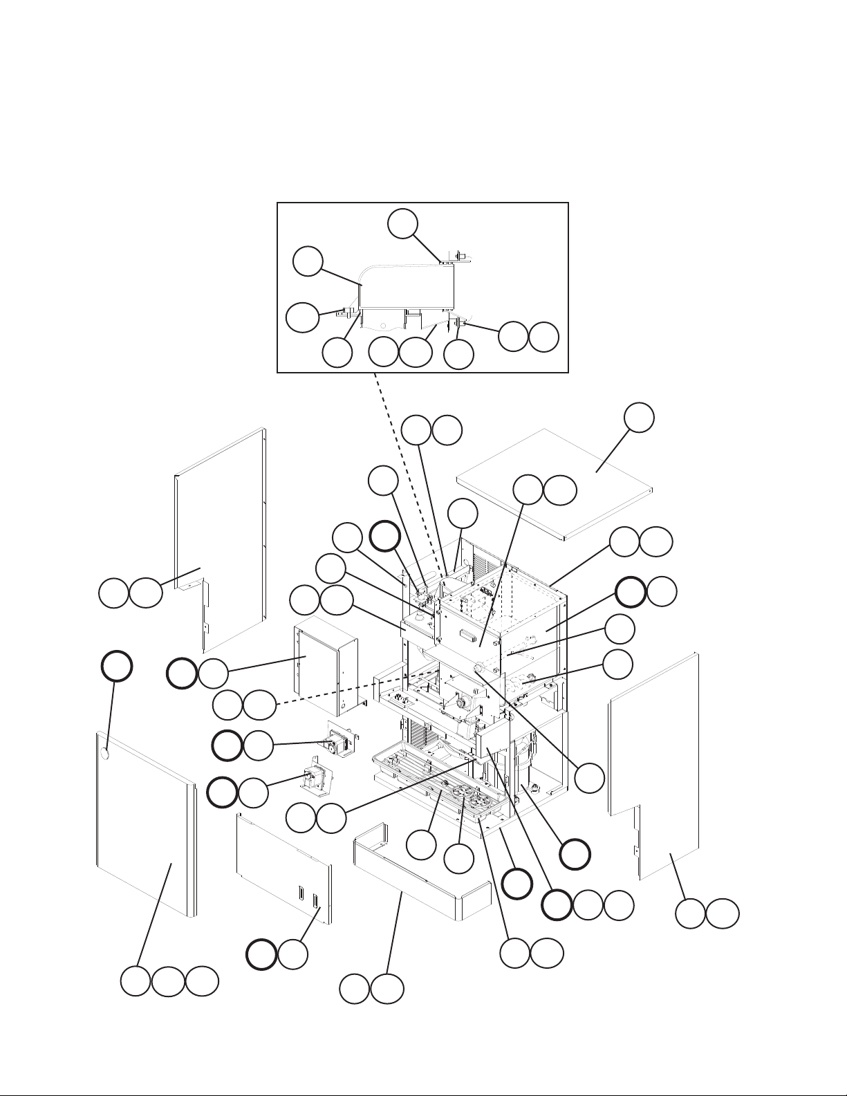
A. Ice Dispenser Assembly
1/2
DCM-500BWH-OS
N-0 to A-0
12
12a
7
1a
1
19a
19
6
8
30
N
30a
E
E1
32
K
J
32a
J1
K1
21
2
5
21a
2a
18
17
29
L
20
29a
L1
10
11
25
22
4
D
15
15a
9
15
15a
15b
F
F1
13
13a
14
10
3
B
M
G1
G2
31
31a
16
G
16a
A. Ice Dispenser Assembly
2/2
DCM-500BWH-OS
N-0 to A-0
H
23
H1
23a
S-1 to V-2
24
28b
28a
C
26
25
24
V-3 and later
25
C
28b
28a
26
26a
28
27a
27
26b
26b
26a
28
See "M. Frame Assembly," items 6 and 6a.
11

Title: A. Ice Dispenser Assembly Model: DCM-500BWH-OS
Required Number
N-0
Index
No. Description
B Refrigeration Circuit 2A2399A01 1 1 1 1 1 -
C Icemaking Unit 3A0623A03 1 1 1 -
D Water Circuit 2A0395A02 1 1 1 -
E Control Box Assembly 2A2615A02 1 1 -
E1 Truss Head Screw 4×8 7C31-0408 3 3 3 3 3 3 3 3 3 -
FT Screw 4×8, SS 7F32-0408 4
F Apron Panel Assembly 3A2502A01 1 -
F1 Truss Head Screw 4×8, SS 7C32-0408 4 4 4 4 4 4 4 4 4 4
G Middle Front Frame
Assembly
G1 Taper Collar SS 4H0171-01 2 2 2 2 2 2 2 2 2 2
G2 Flat Head Screw 4×12, SS 7C22-0412 2 2 2 2 2 2 2 2 2 2
H Shutter Assembly 2A0410A01 1 1 1 1 1 1 1 1 1 1
H1 Truss Head Screw 4×8, SS 7C32-0408 2 2 2 2 -
FT Screw 7F32-0408 2 2 2 2 2 2
J Gear Motor Assembly
(Agitator)
J1 Thumbscrew 415949G12 2 2 2 2 2 2 2 2 2 2
K Gear Motor Assembly
(Dispense)
K1 Thumbscrew 415949G12 2 2 2 2 2 2 2 2 2 2
L Bin Assembly 2A0413A01 1 1 1 1 1 1 -
L1 Truss Head Screw 4×12, SS 7C32-0412 2 2 2 2 2 2 -
FT Screw 4×8, SS 7F32-0408 3 3 3 3
M Frame Assembly 2A0388A06 1 1 1 1 1 1 -
N Label Location 2A2604A02 1 1 1 -
Material or
Model Number Part Number
2A5917A01 1 1 1 2A5917A02 1 1
3A0623A04 1 1 1 1 1 1 1
2A0395A03 1 1 1 2A5455A01 1 1 1 1
2A2615A04 1 2A2615A06 1 2A2615A08 1 2A2615A10 1 2A5460A05 1 1 1 1
3A3618A01 1 1 1 1 1 1 1 1 1
2A2603A01 1 1 1 1 2A2603A02 1 1 1 1 1 1
4A0620A01 1 1 1 1 1 1 1 1 1 1
4A0622A01 1 1 1 1 1 1 1 1 1 1
2A0413A02 1 1 1 1
2A5324A02 1 1 1 1
2A2604A04 1 1 1 1 1 1 1
to
Q-0 Q-1
R-0
to
S-0
S-1
U-1
to
to
U-0
V-0 V- 2 V-3 V-4 V- 5 A-0
1 Spout (B) 208807-01 1 1 1 1 1 1 1 1 1 1
1a Thumbscrew 415949G11 4 4 4 4 4 4 4 4 4 4
2 Spout Cover 215773-01 1 1 1 1 1 1 1 1 1 1
2a Thumbscrew 415949G08 2 2 2 2 2 2 2 2 2 2
3 Cup Guide 326702-01 2 2 2 2 2
4 Bushing 428394-02 1 1 1 1
2 2 2 2 2
12

Title: A. Ice Dispenser Assembly Model: DCM-500BWH-OS
Required Number
N-0
Index
No. Description
5 Bushing SR-30-1 420472-03 1 1 1 1 1 -
Cable Tie 8911-0150 1 1 1 1 1
6 Packing 427151-02 1 1 1 1 1 1 1 1 1 1
7 Packing (A) Spout 427195-01 1 1 1 1 1 1 1 1 1 1
8 Packing (B) Spout 427196-01 1 1 1 1 1 1 1 1 1 1
9 Gasket 429758-01 2 2 2 2 2 2 2 2 2 2
10 Square Washer 433537-02 1 1 1 1 1 1 1 1 1 1
11 Grounding Screw 433304-02 1 1 1 1 1 1 1 1 1 1
12 Spout 103329G01 1 1 1 1 1 1 1 1 1 1
12a Thumbscrew 415949G11 3 3 3 3 3 3 3 3 3 3
13 Panel (Lo) SS 2A0699G01 1 1 1 1 1 1 1 1 1 1
13a FT Screw 4×8, SS 7F32-0408 6 6 6 6 6 6 6 6 6 6
14 Grille 2A0827G01 1 1 1 1 1 1 1 1 1 1
15 Bin Cover 2A0880A02 1 1 1 1 1 1 1 1 1 1
15a Thumbscrew 415949G12 4 4 4 4 4 4 4 4 4
16 Drip Tray 2A2591G01 1 1 1 1 1 1 1 1 1 1
16a Truss Head Screw 4×8, SS 7C32-0408 4 4 4 4 4 -
FT Screw 7F32-0408 4 4 4 4 4
17 Auger (Dispense) SS 339192G01 1 1 1 1 1 1 1 1 1 1
18 Agitator SS 3A0895G01 1 1 1 1 1 1 1 1 1 1
19 Evaporator Bracket SS 3A0360-01 1 1 1 1 1 1 1 1 1 1
19a Hex Bolt w/Washer
(LF)
20 Top Panel SS 3A2514G01 1 1 1 1 1 1 1 1 1 1
21 Reservoir Bracket 3A5675-01 1 1 1 1
21a FT Screw 7F32-0408 2 2 2 2
22 Wire Saddle 4A0338-01 2 2 2 2
23 Ice Chute 4A2204-01 1 1 1 1 1 1 1 1 1 1
23a Thumbscrew 415949G08 2 2 2 2 2 2 2 2 2 2
24 Heater (includes
item25)
25 Spring 4A2292F01 1 1 1 1 1 1 1
26 Gear Motor Bracket SS 4A4308-01 1 1 1 1 1 1 1
26a Hex Head Bolt 8×12, SS
26b Split Lock Washer M8, SS 7L22-0800 3 3 3 3 3 3 3
27 Drain Pan Bracket
Assembly
27a Hex Head Bolt 8×12, SS 7B02-0812 3 3 3
28 Drain Pan Assembly 323765G02 See "D. Water
28a Flat Washer M8, SS 7W22-0800 4 4 4 4 4 4 4
28b Allen Head Cap Screw 8×20, SS 7S12-0820 4 4 4 4 4 4 4
29 Rear Panel GS 2A2471-01 1 1 1 1 1 1 -
29a Truss Head Screw 4×8, SS 7C32-0408 4 4 4 4 4 4 -
FT Screw 7F32-0408 4 4 4 4
Material or
Model Number Part Number
5×10, SS 7B0230510 2 2 2 2 2 2 2 2 2 2
4A2292-01 1 1 1 1 1 1 1
7B02-0812 3 3 3 3 3 3 3
SS 4A4315G01 1 1 1 See "M. Frame
4A4354G01 1 1 1 4A4354G02 1 1 1 1
2A5402-01 1 1 1 1
to
Q-0 Q-1
Circuit," item 40.
R-0
to
S-0
S-1
U-1
to
to
U-0
V-0 V- 2 V-3 V-4 V- 5 A-0
Assembly,"
items 6 and 6a
-
13
Title: A. Ice Dispenser Assembly Model: DCM-500BWH-OS
Required Number
N-0
Index
No. Description
30 Side Panel (L) SS 2A2624-01 1 1 1 1 1 1 -
30a Truss Head Screw 4×8, SS 7C32-0408 6 6 6 6 6 6 -
FT Screw 7F32-0408 6 6 6 6
31 Side Panel (R) SS 2A2625-01 1 1 1 1 1 1 -
31a Truss Head Screw 4×8, SS 7C32-0408 6 6 6 6 6 6 -
FT Screw 7F32-0408 6 6 6 6
32 Gear Motor Cover 3A1058-01 1 1 1 See "C. Icemaking Unit."
32a Truss Head Screw 4×8, SS 7C32-0408 2 2 2
Material or
Model Number Part Number
2A6142-01 1 1 1 1
2A6141-01 1 1 1 1
to
Q-0 Q-1
R-0
to
S-0
S-1
U-1
to
to
U-0
V-0 V- 2 V-3 V-4 V- 5 A-0
14
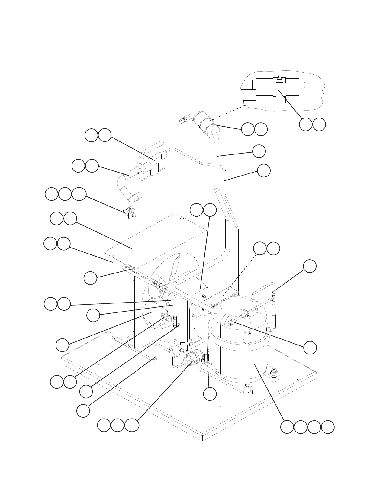
B. Refrigeration Circuit
DCM-500BAH-OS
M-0 to V-0
17
16
13
26
23a
23
22
5a
5
20
24
26
12
11
6a
6
21
4a
4
7
18 26
7a
8
10
25
27
2
3
19
9
27
9
14 15
15a
15
1a11b
1c
 Loading...