

Hoshizaki American, Inc. DB-200H Part Manual
Hoshizaki
“A Superior Degree
of Reliability”
www.hoshizaki.com
Model
DB-200H
Ice Dispensing Bin
Hoshizaki America, Inc.
Number: 71204
Issued: 4-9-2002
Revised: 4-19-200
6
PARTS LIST

CONTENTS
Auxiliary Codes ...................................................................................................................... 3
Note About Ordering Parts .................................................................................................... 3
Material Abbreviations ........................................................................................................... 4
A. Dispensing Bin Assembly .................................................................................................. 5
B. Mechanism Assembly ....................................................................................................... 9
C. Front Panel Assembly ..................................................................................................... 11
D. Spout Switch Assembly ................................................................................................... 12
E. Solenoid Assembly .......................................................................................................... 13
F. Drain Pan Assembly ......................................................................................................... 15
G. Shutter Assembly ............................................................................................................ 16
H. Safety Switch Assembly .................................................................................................. 17
J. Spout Assembly ............................................................................................................... 18
K. Label Location ................................................................................................................. 19
L. Frame ............................................................................................................................... 21
M. Gear Motor Assembly ..................................................................................................... 22
N. Accessories and Packaging ............................................................................................ 23
2

Auxiliary Codes
DB-200H L-0 September 2001
M-0 December 2001
M-1 June 2002
N-0 December 2002
P-0 December 2003
P-5 October 2004
Q-5 December 2004
R-5 December 2005
Note About Ordering Parts
Most assemblies cannot be ordered as complete units; parts in the assemblies generally
must be ordered separately.
3

Material Abbreviations
ALUMINUM
AL = Aluminum
COPPER
CU = Copper
PLASTIC
ABS = Acrylonitrile -butadiene - styrene
AC = Polyacetal
EVA = Ethylene vinyl acetate
PA = Polyamide = Nylon
PC = Polycarbonate
PE = Polyethylene
PES = Polyester
PETP = Polyethylene terephthalate = Tetlon
PP = Polypropylene
PS = Polystyrene
PTFE = Polytetrafluoroethylene = Teflon
PUR = Polyurethane
PVC = Polyvinyl chloride
RUBBER
VN = Vinyl Nitrile
EPDM = EP rubber
NBR = Nitrile butadiene rubber
NR = Natural rubber
NP = Neoprene
SI.R = Silicone rubber
SY.R = Synthetic rubber
EPH = Epichlorohydrin
STEEL
GS = Galvanized steel
SS = Stainless steel
PS = Plated steel
PAS = Primed steel
AUXILIARY CODE
K-0
Designates the year. "K" indicates the year 2000. Years progress or regress in alphabetical order.
"J" is 1999, "L" is 2001, "M" is 2002, and so on. The letters "I" and "O" were skipped.
Designates significant part changes within the same year for this model. Base is 5 (0 for auxiliary
codes P-0 and earlier) and this number advances for each change.
Example: P-6
"P" indicates 2004.
"6" indicates the first significant part change for 2004.
4
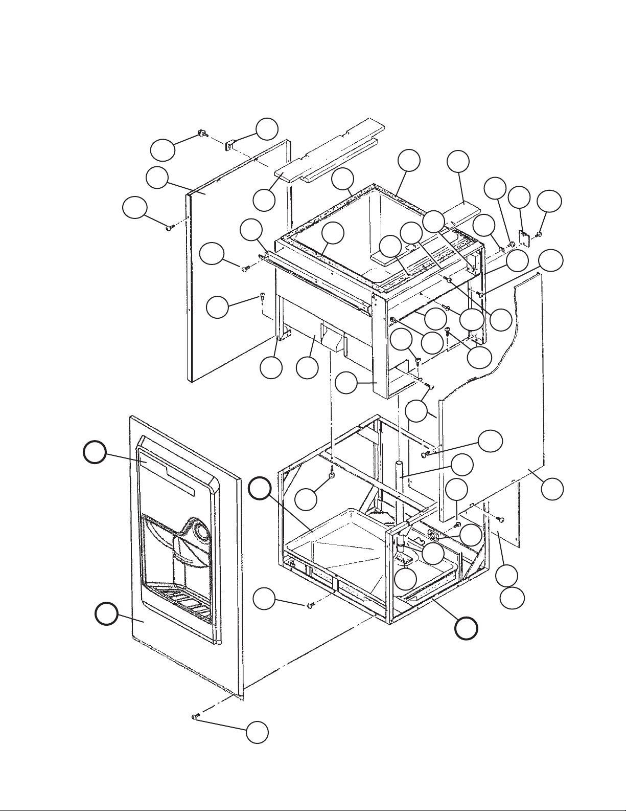
A. Dispensing Bin Assembly
(1/2)
DB-200H
L-0 through R-5
23a
17
17a
20a
3a
22
20
23
30
29
29
30
21
12
15
15a
14
9
27
27a
13
9a
10
10a
K
C
F
F2
8b
3
2
8
2a
32
8a
28
18
F1
10b
17a
1
17
31
16
16a
L
C1
5
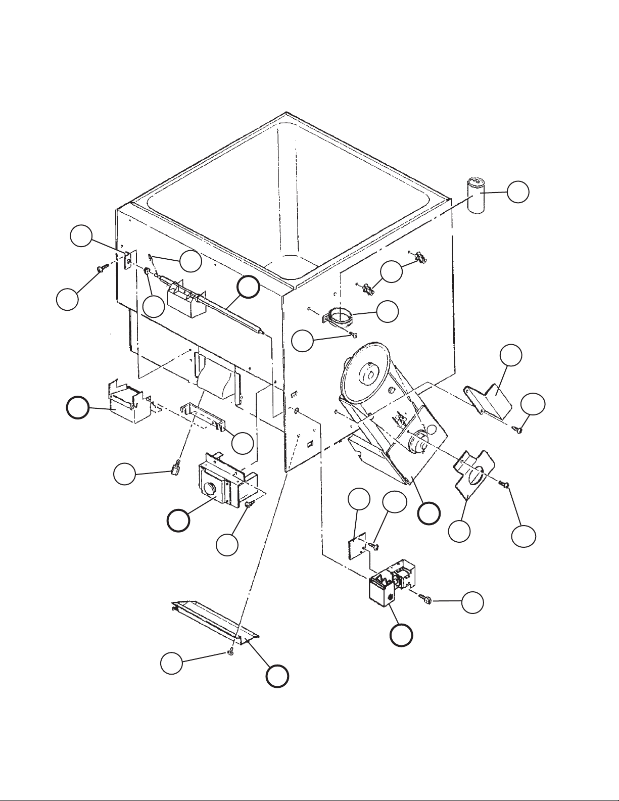
A. Dispensing Bin Assembly
(2/2)
DB-200H
L-0 through R-5
5
G1
5a
6
19
11
G
4
4a
24
J
7a
H1
D
D1
24a
7
26
26a
B
25
E1
25a
E
H
6

Title: A. Dispensing Bin Assembly Model: DB-200H
M-1
Index
No. Description
B Mechanism Assembly - 1A0109A01 1 1 1
C Front Panel Assembly - 1A0615A01 1 1 1
C1 Truss Head Screw 4×8, SS 7C32-0408 2 2 2
D Spout Switch Assembly - 4A2465A01 1 1 1
D1 T2 Screw 4×8 7P31-0408 2 2 2
E Solenoid Assembly - 2A0585A01 1 1 1
E1 Hex Head Bolt w/Washer (LF) 4×10, SS 7B0230410 4 4 4
F Drain Pan Assembly - 212963A02 1 1 1
F1 Truss Head Screw 5×12, SS 7C32-0512 2 2 2
F2 Truss Head Screw 4×8, SS 7C32-0408 2 2 2
G Shutter Assembly - 328650A01 1 1 1
G1 Snap Pin SSP-6, SS 715S-0006 1 1 1
H Safety Switch Assembly - 435549A01 1 1 1
H1 T2 Screw 4×8, SS 7P32-0408 4 4 4
J Spout Assembly - 326007A01 1 1 1
K Label Location - 2A2236A01 1 -
L Frame - 3A0184A01 1 1 1
Material or
Model Number Part Number
2A2629A01 1 1
L-0
M-0
to
P-0
Required Number
P-5
to
R-5
1 Vinyl Hose L=445 7716-2025 1 1 1
2 Bin Body - 106184G01 1 1 1
2a Hex Head Bolt w/Washer (LF) 8×20 7B0130820 4 4 4
3 Frame (E) GS 323052-01 1 1 1
3a FT Screw 4×8, SS 7F32-0408 3 3 3
4 Strap - 4A0506-01 1 1 1
4a FT Screw 4×12, SS 7F32-0412 1 1 1
5 Collar - Bracket GS 439399-01 1 1 1
5a T2 Screw 4×8, SS 7P32-0408 2 2 2
6 Collar - Shutter POLYOXY-
METHYLENE
7 Hook SS 439398-01 1 1 1
7a Thumbscrew ABS, SS 415949G01 2 2 -
8 Control Box (A) GS 217314-01 1 1 1
8a T2 Screw 4×8 7P31-0408 3 3 3
8b FT Screw 4×8, SS 7F32-0408 2 2 2
9 Control Box (B) GS 323683G01 1 1 1
9a T2 Screw 4×8 7P31-0408 3 3 3
10 Control Box (C) GS 323186G02 1 1 1
10a T2 Screw 4×8 7P31-0408 3 3 3
10b FT Screw 4×8, SS 7F32-0408 1 1 1
11 Clamp NO. 4253 427902-05 5 5 5
12 Screw - Grounding BRASS 433304-02 1 1 1
13 Square Washer COPPER 433537-02 1 1 1
435533-01 1 1 1
415949G12 2
7
 Loading...