

Hoshizaki America TempGuard Service Manual
Hoshizaki
“A Superior Degree
of Reliability”
www.hoshizaki.com
Models
TempGuard
Commercial Refrigerators & Freezers
Hoshizaki America, Inc.
Number: 73077
Issued: 3-8-1999
Revised: 2-21-2007
SERVICE MANUAL
®
®

IMPORTANT
Only qualified service technicians should attempt to service or maintain this
unit. No such service or maintenance should be undertaken until the technician
has thoroughly read this Service Manual.
HOSHIZAKI provides this manual primarily to assist qualified service technicians in the
service and maintenance of the unit.
Should the reader have any questions or concerns which have not been satisfactorily
addressed, please call, write or send an e-mail message to the HOSHIZAKI Technical
Support Department for assistance.
HOSHIZAKI AMERICA, INC.
618 Highway 74 South
Peachtree City, GA 30269
Attn: HOSHIZAKI Technical Support Department
Phone: 1-800-233-1940 Technical Service
(770) 487-2331
Fax: 1-800-843-1056
(770) 487-3360
E-mail: techsupport@hoshizaki.com
Web Site: www.hoshizaki.com
NOTE: To expedite assistance, all correspondence/communication MUST include the
following information:
• Model Number
• Serial Number
• Complete and detailed explanation of the problem
2

Please review this manual. It should be read carefully before the unit is serviced or
maintenance operations are performed. Only qualified service technicians should service
and maintain the unit. This manual should be made available to the technician prior to
service or maintenance.
CONTENTS
I. Specifications ...................................................................................................................... 5
A. Nameplate Ratings........................................................................................................ 5
B. Dimensions ................................................................................................................... 6
1. Notes for All Units .................................................................................................... 6
2. RH1-SSB(-HD), FH1-SSB(-HD), RFH1-SSB-HD, RH1-SSB-GD ............................ 7
3. RH2-SSB(-HD), FH2-SSB(-HD), RFH2-SSB(-HD), RH2-SSB-GD ......................... 8
4. RH3-SSB(-HD), FH3-SSB(-HD), RFH3-SSB(-HD), RH3-SSB-GD ......................... 9
5. PTR1SSB-xxxx, PTR1-SSB01-10 ......................................................................... 10
II. General Information ......................................................................................................... 11
A. Sequence of Operation and Timing Charts ................................................................. 11
1. Refrigerator and Refrigerator Side of Dual Temp Models ...................................... 11
2. Freezer (except freezer side of RFH1-SSB-HD) auxiliary code P5 and earlier .....
3. Freezer (except freezer side of RFH1-SSB-HD) auxiliary code P6 and later ........ 15
4. Freezer Side of RFH1-SSB-HD ............................................................................. 17
B. Display Board .............................................................................................................. 19
C. Control Board .............................................................................................................. 20
1. Location ................................................................................................................. 20
2. Control Board Layout .............................................................................................
D. Settings and Diagnostics ............................................................................................. 22
1. Guarded Access Menu ......................................................................................... 22
a) Temperature Setpoint ...................................................................................... 22
b) Defrost Frequency ......................................................................................... 22
c) Temperature Display Scale (°F or °C) .............................................................. 23
2. Diagnostics Menu ................................................................................................. 24
E. Alarm Signals and Countermeasures ......................................................................... 25
F. Compressor Protector .................................................................................................. 26
G. Perimeter Frame Heater ............................................................................................. 26
H. Glass Door Heater ...................................................................................................... 26
III. Service Diagnosis ........................................................................................................... 27
A. Diagnosis Chart .......................................................................................................... 27
B. Thermistor Check ........................................................................................................ 30
IV. Removal and Replacement of Components ................................................................... 31
A. Service for Refrigerant Lines ...................................................................................... 31
1. Refrigerant Recovery ............................................................................................. 31
2. Brazing .................................................................................................................. 31
3. Evacuation and Recharge ..................................................................................... 32
B. Removal and Replacement of Compressor ................................................................ 33
C. Removal and Replacement of Expansion Valve ......................................................... 34
D. Removal and Replacement of Evaporator .................................................................. 35
E. Removal and Replacement of Evaporator Fan Shroud Assembly .............................. 36
F. Removal and Replacement of Heat Shield on FH2-SSB(-HD) .................................... 37
G. Removal and Replacement of Door Gasket ............................................................... 37
13
21
3

H. Removal and Replacement of Door Closure Spring ................................................... 38
I. Removal and Replacement of Control Board ............................................................... 39
J. Door Re-Hinging (except glass doors) ......................................................................... 40
V. Cleaning Instructions ....................................................................................................... 41
VI. Wiring Diagrams ............................................................................................................. 42
A1. RH1-SSB(-HD) (auxiliary code L5 and earlier) ......................................................... 42
A2. RH1-SSB(-HD) (auxiliary code M5 and later) ...........................................................
B1. RH2-SSB(-HD) (auxiliary code L5 and earlier) .........................................................
B2. RH2-SSB(-HD) (auxiliary code M5 and later) ........................................................... 45
C1. RH3-SSB(-HD) (auxiliary code L5 and earlier) ......................................................... 46
C2. RH3-SSB(-HD) (auxiliary code M5 and later) ........................................................... 47
D1. RH1-SSB-GD (auxiliary code N6 and earlier) ........................................................... 48
D2. RH1-SSB-GD (auxiliary code P5 and later) ..............................................................
E1. RH2-SSB-GD (auxiliary code N6 and earlier) ........................................................... 50
E2. RH2-SSB-GD (auxiliary code P5 and later) .............................................................. 51
F1. RH3-SSB-GD (auxiliary code K0) ............................................................................. 52
F2. RH3-SSB-GD (auxiliary code N6 and later) .............................................................. 53
G1. FH1-SSB(-HD) (auxiliary code P5 and earlier) ......................................................... 54
G2. FH1-SSB(-HD) (auxiliary code P6 and later) ............................................................ 55
H1. FH2-SSB(-HD) (auxiliary code P5 and earlier) ......................................................... 56
H2. FH2-SSB(-HD) (auxiliary code P6 and later) ............................................................ 57
I. RFH1-SSB-HD ............................................................................................................. 58
1. Refrigerator ........................................................................................................... 58
2a. Freezer (auxiliary code P5 and earlier) ............................................................... 59
2b. Freezer (auxiliary code Q5 and later) .................................................................. 60
J. RFH2-SSB(-HD) .......................................................................................................... 61
K. RFH3-SSB(-HD).......................................................................................................... 61
L. RIR2-SSB51-02 ........................................................................................................... 62
M. PTR1SSB-xxxx, PTR1-SSB01-10 .............................................................................. 63
43
44
49
4
I. Specifications
A. Nameplate Ratings
Design Pressure (PSIG) Refrigerant
AC Supply Voltage Amperes HI LO R-404A
RH1-SSB / RH1-SSB-HD 115/60/1 7.0 450 200 12.2 OZ
RH1-SSB-GD 115/60/1 10.7 450 200 16.1 OZ
FH1-SSB / FH1-SSB-HD 115/60/1 12.0 450 250 15.2 OZ
RH2-SSB / RH2-SSB-HD
RH2-SSB-GD
FH2-SSB / FH2-SSB-HD
RH3-SSB / RH3-SSB-HD 115/60/1 13.0 450 200 23.2 OZ
RH3-SSB-GD 115/60/1 15.5 450 250 31.4 OZ
RIR2-SSB51-02
PTR1SSB-xxxx / PTR1-SSB01-10 115/60/1 12.0 450 250 15.5 OZ
AC Supply
Voltage Amperes
RFH2-SSB / RFH2-SSB-HD
RFH3-SSB / RFH3-SSB-HD 115/60/1 22 450 200 450 250 18.2 OZ 15.2 OZ
RFH1-SSB-HD 115/60/1 16.0 450 250 450 250 9.5 OZ 12.0 OZ
115/60/1 19 450 200 450 250 12.2 OZ 15.2 OZ
115/60/1 10.0 450 200 18.2 OZ
115/60/1 11.8 400 200 21.5 OZ
115/60/1 15.5 450 250 20.1 OZ
115/60/1 11.0 450 200 18.2 OZ
Design Pressure (PSIG) Refrigerant
Refrigerator Freezer R-404A
HI LO HI LO Refrigerator Freezer
See the nameplate for electrical and refrigeration specifications. The nameplate is located
on the right side wall of the cabinet interior.
Note: We reserve the right to make changes in specifications and design without prior
notice.
5
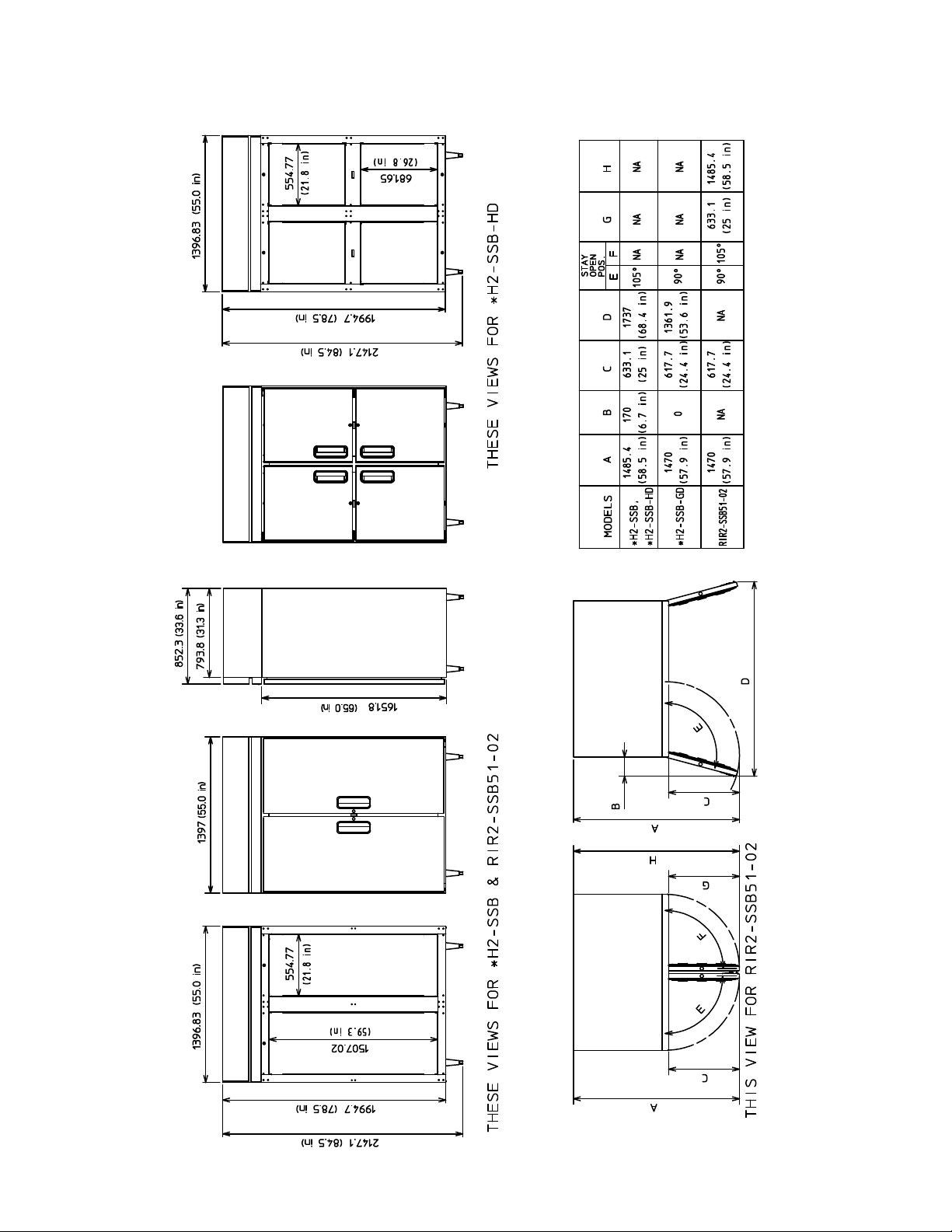
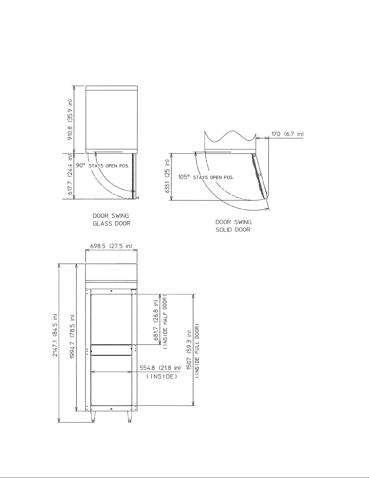
B. Dimensions
1. Notes for All Units
a) Units: mm (in.)
b) Legs have 25.4 mm (1 in.) height adjustment
Door Opening Total Refrigerated
Width
mm (in.)
RH1-SSB / FH1-SSB 554.8 (21.8) 1507(59.3) 22.3 11.5
RH1-SSB-GD 554.8 (21.8) 1507(59.3) 22.3
RH1-SSB-HD / FH1-SSB-HD 554.8 (21.8) 681.7(26.8) 22.3
RH2-SSB / FH2-SSB 554.8 (21.8)
RH2-SSB-GD / RIR2-SSB51-02 554.8 (21.8)
RH2-SSB-HD / FH2-SSB-HD 554.8 (21.8) 681.7(26.8)
RH3-SSB / FH3-SSB 554.8 (21.8) 1507(59.3) 73.7 39
RH3-SSB-GD 554.8 (21.8) 1507(59.3) 73.7
RH3-SSB-HD / FH3-SSB-HD 554.8 (21.8) 681.7(26.8) 73.7
RFH2-SSB 554.8 (21.8)
RFH2-SSB-HD 554.8 (21.8) 681.7(26.8) 22.3 22.3
RFH3-SSB 554.8 (21.8) 1507(59.3) 48.3 22.3 25.3 11.5
RFH3-SSB-HD 554.8 (21.8) 681.7(26.8) 48.3 22.3 25.3 11.5
RFH1-SSB-HD 554.8 (21.8) 681.7 (26.8) 9.1 10.5 11.5 (total)
Height
mm (in.)
1507(59.3) 48.3 25.3
1507(59.3) 48.3
1507(59.3) 22.3 22.3 11.5 11.5
Volume ft
Refrigerator Freezer Refrigerator Freezer
3
48.3
Total Shelf Space ft
11.5 11.5
2
Depth with
Doors Open
PTR1SSB-FSFS 2,177 (85.9) 554.8 (21.8) 1507(59.3) 23.8 13.6
PTR1SSB-FGFG 2,146.2 (84.7)
PTR1SSB-HSHS 2,177 (85.9) 554.8 (21.8) 681.7 (26.8)
PTR1SSB-HGHG 2,146.2 (84.7)
PTR1SSB-HGHS /
PTR1-SSB01-10
(Half glass and half solid
door combo)
2,161.6 (85.3)
Door Opening Total Refrigerated
Width
mm (in.)
Height
mm (in.)
Volume ft
3
Total Shelf Space ft
See the nameplate for electrical and refrigeration specifications. The nameplate is located
on the right side wall of the cabinet interior.
Note: We reserve the right to make changes in specifications and design without prior
notice.
2
6
2. RH1-SSB(-HD), FH1-SSB(-HD), RFH1-SSB-HD, RH1-SSB-GD
mm (in.)
7
3. RH2-SSB(-HD), FH2-SSB(-HD), RFH2-SSB(-HD), RH2-SSB-GD
mm (in.)
8
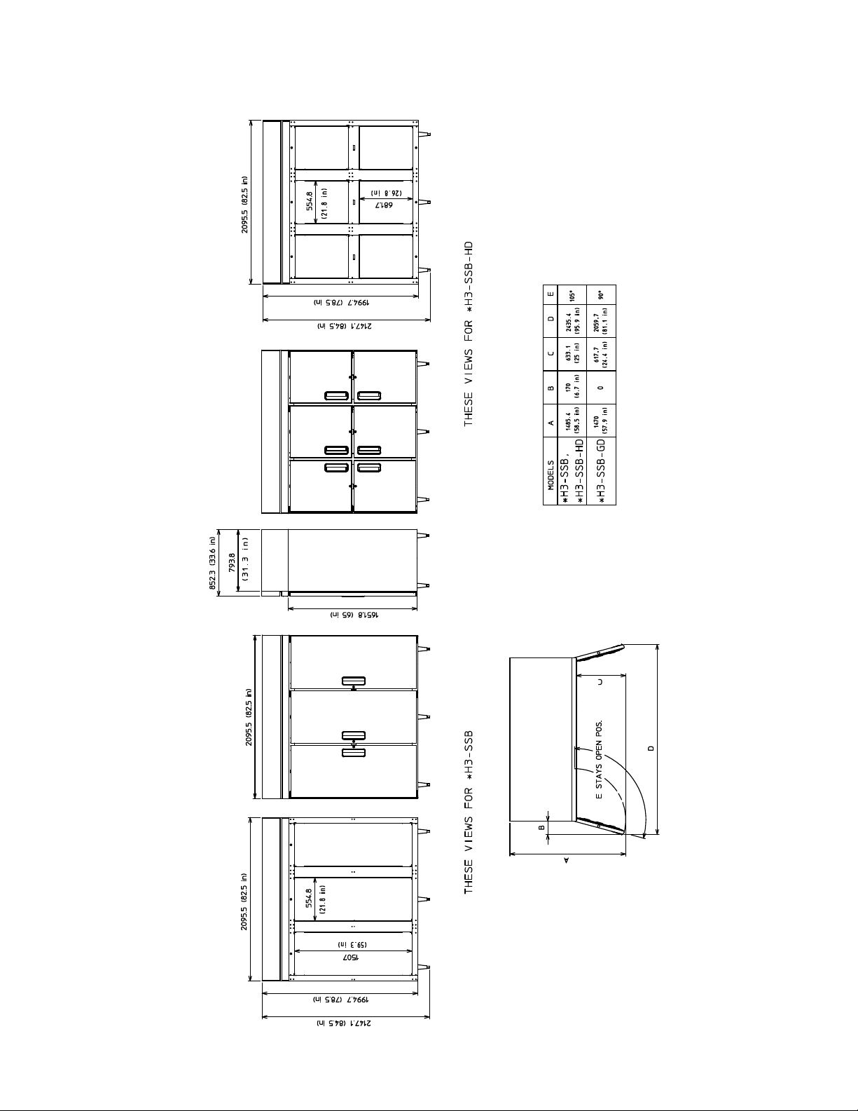
4. RH3-SSB(-HD), FH3-SSB(-HD), RFH3-SSB(-HD), RH3-SSB-GD
mm (in.)
9
5. PTR1SSB-xxxx, PTR1-SSB01-10
mm (in.)
10
II. General Information
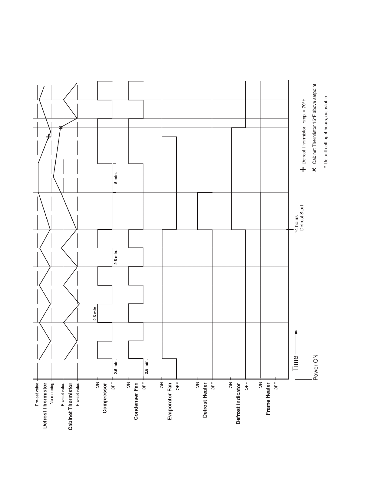
A. Sequence of Operation and Timing Charts
1. Refrigerator and Refrigerator Side of Dual Temp Models
a) Sequence of Operation
POWER ON
Board Self Check
Display reads "r_##"
(## is board revision)
1. Frame heaters on
2. Evaporator fan on
Cycle On (Cut-on
temperature reached)
[Minimum 2.5 minutes]
1. Compressor on
2. Condenser fan on
2.5 minute delay
1. Compressor start-up
2. Condenser fan start-up
If evaporator temperature
reaches 13°F (8°F for Pass Thru),
unit initiates defrost.
1. Compressor off
(Note: Condenser fan and
evaporator fan are on.)
Cycle Off (Cut-out
temperature reached)
[Minimum 2.5 minutes]
1. Compressor off
2. Condenser fan off
Evaporator temperature
reaches 40°F, defrost
terminated
1. Compressor on
2. Condenser fan on
Normal cycling continues
Note: The start circuit of the compressor is timed such that at power-up and during
any compressor off time, there will be at least a 2 1/2 minute delay before the
compressor will start. The only exception is when the overload activates and
deactivates. The compressor has a 2 1/2 minute minimum run time during every
run cycle.
11
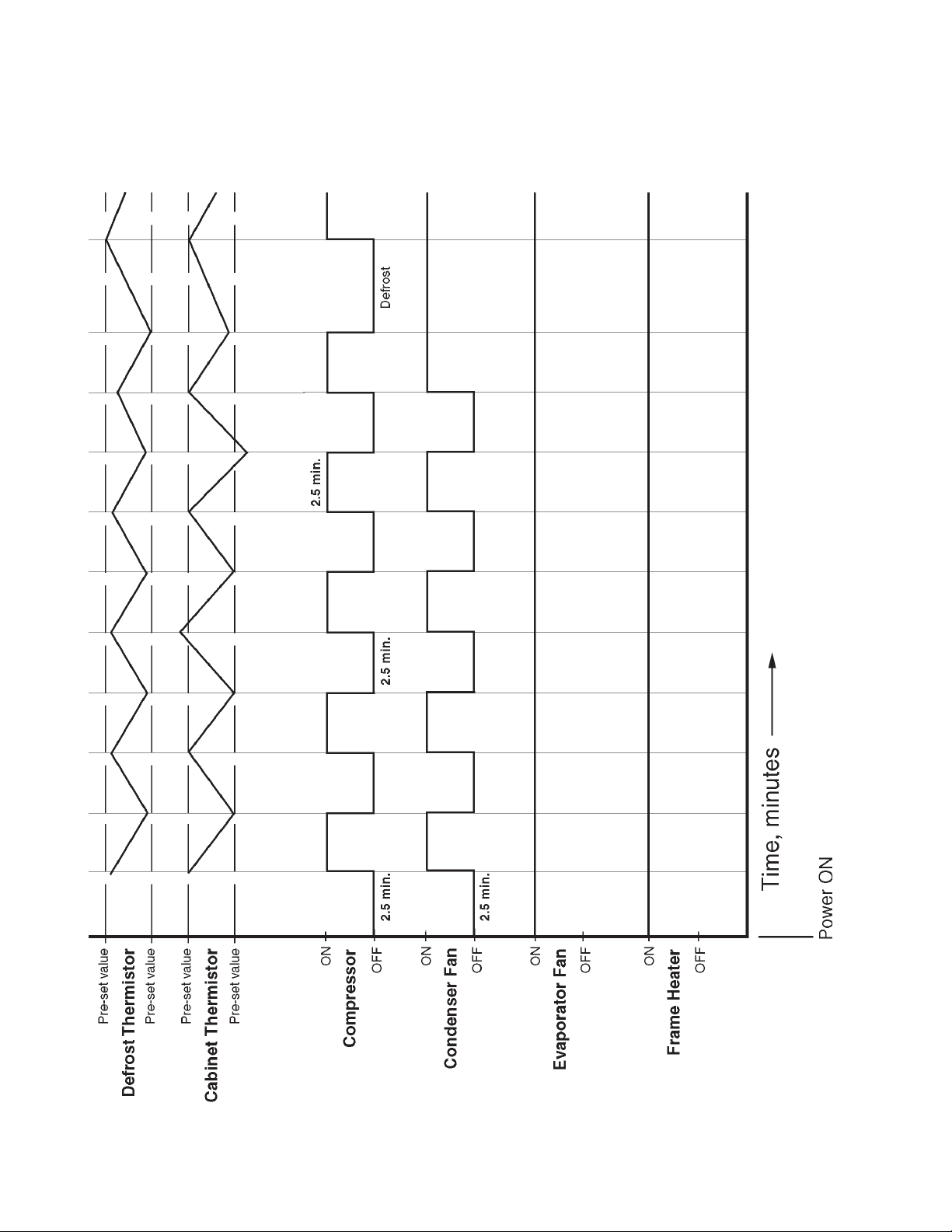
b) Timing Chart
For refrigerator, and refrigerator side of Dual Temp models.
12
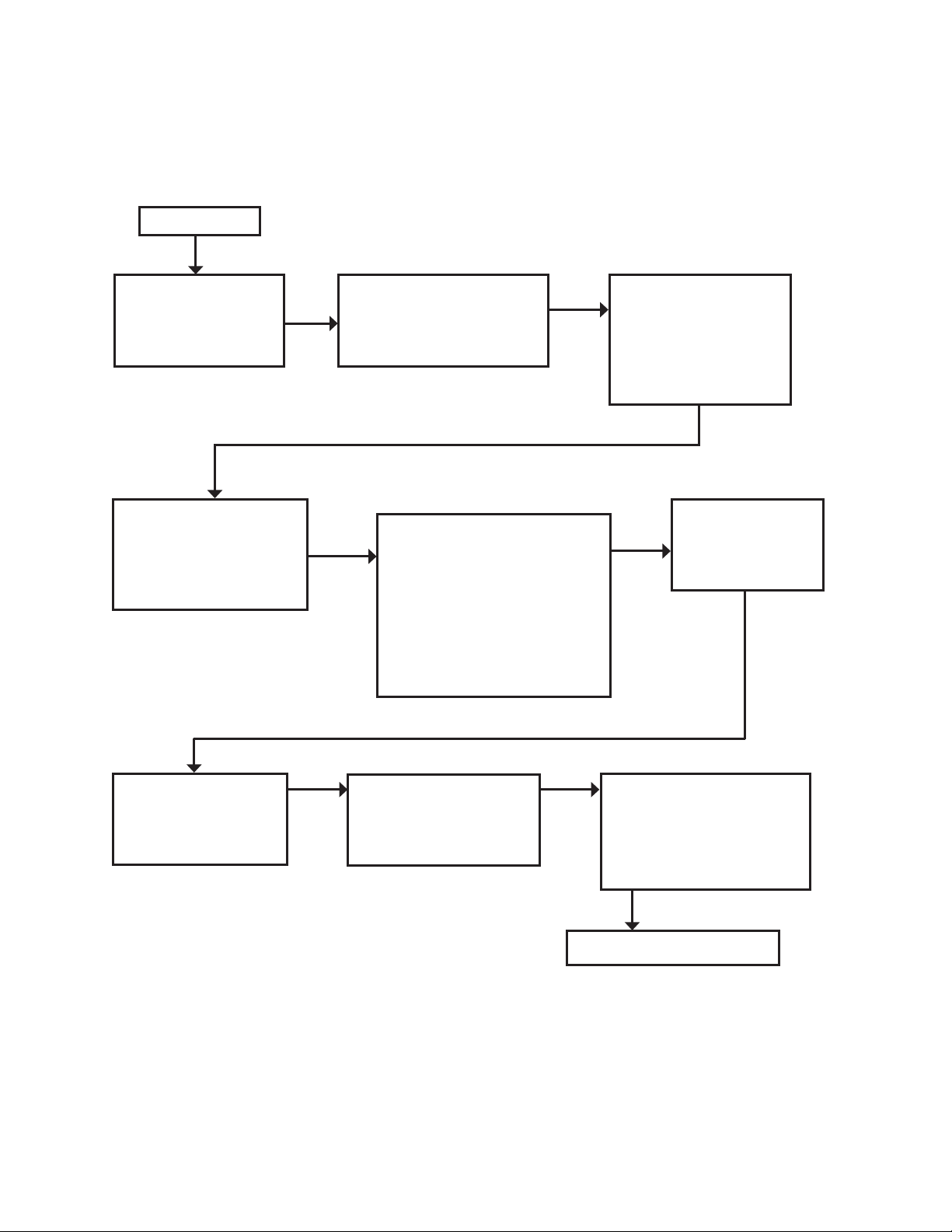
2. Freezer (except freezer side of RFH1-SSB-HD) auxiliary code P5 and earlier
a) Sequence of Operation
POWER ON
Board Self Check
Display reads "r_##"
(## is board revision)
Frame heaters on
Cycle On (Cut-on
temperature reached)
[Minimum 2.5 minutes]
1. Compressor on
2. Condenser on
3. Evaporator on
2.5 minute delay
1. Compressor start-up
2. Condenser fan start-up
3. Evaporator fan start-up
Defrost Start
Preprogrammed time interval
1. Compressor off
2. Evaporator fan off
3. Condenser fan off
4. Defrost heater on
5. "dEF" displayed
Cycle Off (Cut-out
temperature reached)
[Minimum 2.5 minutes]
1. Compressor off
2. Condenser fan off
3. Evaporator fan off
Defrost End
Defrost thermistor
reaches 100°F;
Defrost heater off
Five minutes after
defrost heater off
1. Compressor on
2. Condenser fan on
Note: The start circuit of the compressor is timed such that at power-up and during
any compressor off time, there will be at least a 2 1/2 minute delay before the
compressor will start. The only exception is when the overload activates and
deactivates. The compressor has a 2 1/2 minute minimum run time during every
run cycle.
Evaporator temperature
reaches below 70°F
1. Evaporator fan on
13
Cabinet temperature reads
a value below 15°F above
the setpoint.
"dEF" no longer displayed,
cabinet temp. displayed.
Normal cycling continues
b) Timing Chart
For freezer (except freezer side of RFH1-SSB-HD) auxiliary code P5 and earlier.
14
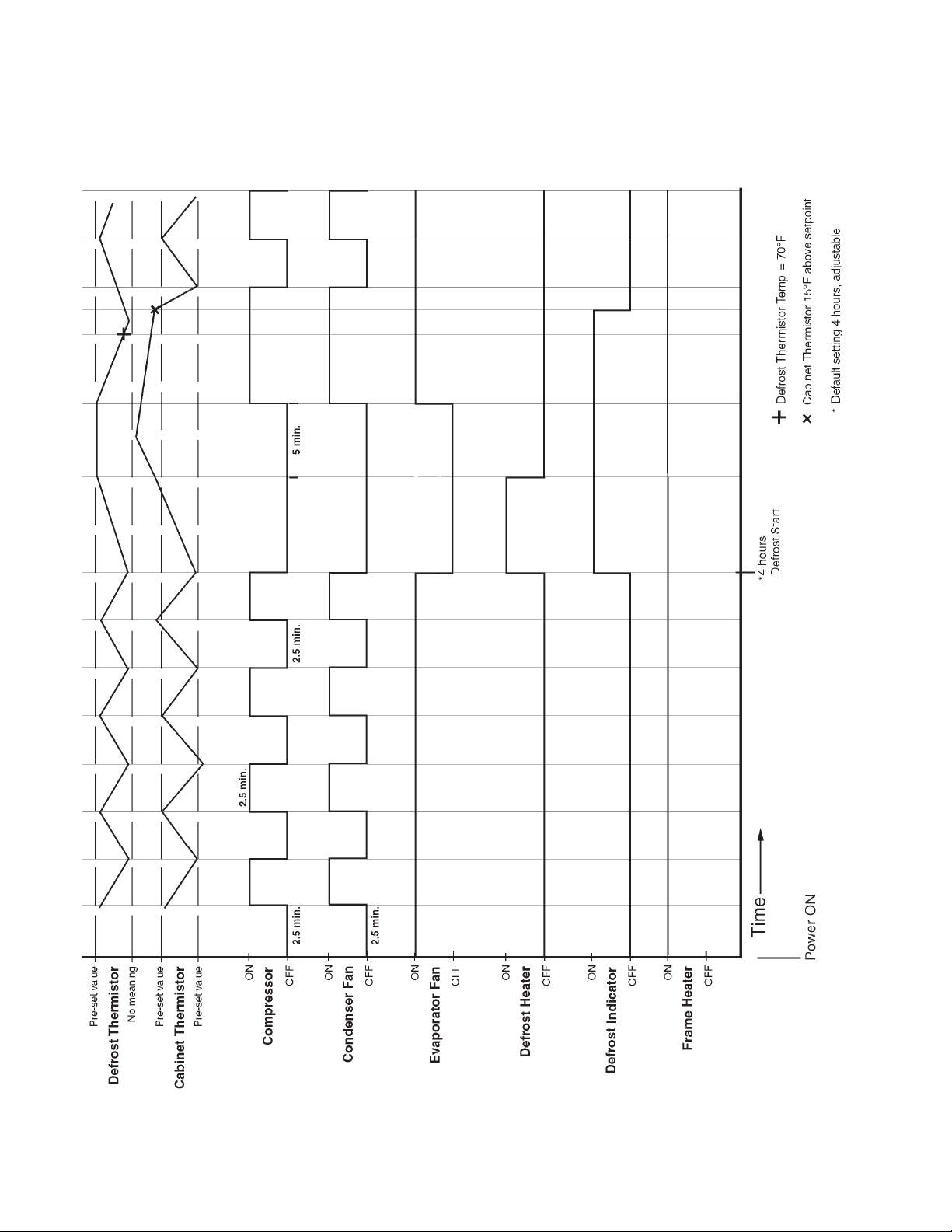
3. Freezer (except freezer side of RFH1-SSB-HD) auxiliary code P6 and later
a) Sequence of Operation
POWER ON
Board Self Check
Display reads "r_##"
(## is board revision)
1. Frame heaters on
2. Evaporator fan on
Cycle On (Cut-on
temperature reached)
[Minimum 2.5 minutes]
1. Compressor on
2. Condenser fan on
2.5 minute delay
1. Compressor start-up
2. Condenser fan start-up
Defrost Start
Preprogrammed time interval
1. Compressor off
2. Evaporator fan off
3. Condenser fan off
4. Defrost heater on
5. "dEF" displayed
Cycle Off (Cut-out
temperature reached)
[Minimum 2.5 minutes]
1. Compressor off
2. Condenser fan off
Defrost End
Defrost thermistor
reaches 100°F;
Defrost heater off
Five minutes after
defrost heater off
1. Compressor on
2. Condenser fan on
Evaporator temperature
reaches below 70°F
1. Evaporator fan on
Normal cycling continues
Cabinet temperature reads
a value below 15°F above
the setpoint.
"dEF" no longer displayed,
cabinet temp. displayed.
Note: The start circuit of the compressor is timed such that at power-up and during
any compressor off time, there will be at least a 2 1/2 minute delay before the
compressor will start. The only exception is when the overload activates and
deactivates. The compressor has a 2 1/2 minute minimum run time during every
run cycle.
15
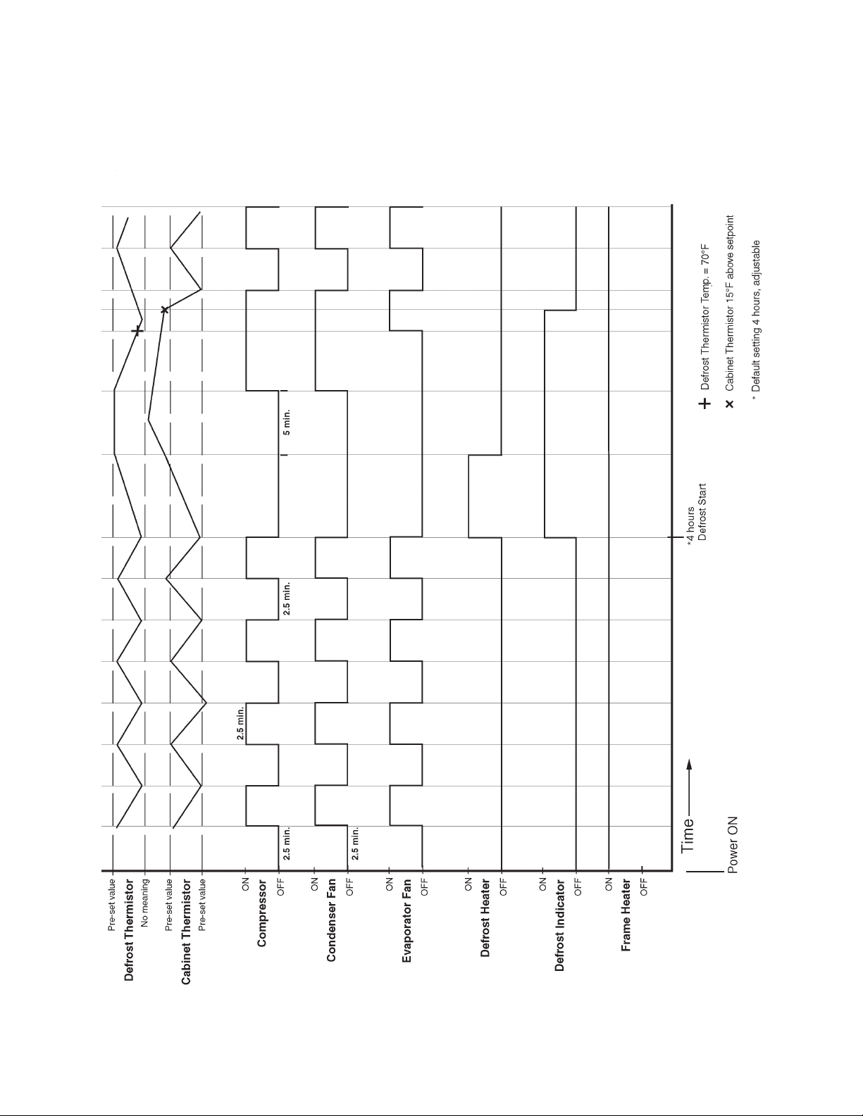
b) Timing Chart
For freezer (except freezer side of RFH1-SSB-HD) auxiliary code P6 and later.
16
4. Freezer Side of RFH1-SSB-HD
a) Sequence of Operation
POWER ON
Board Self Check
Display reads "r_##"
(## is board revision);
Frame heaters on
Cycle On (Cut-on
temperature reached)
[Minimum 2.5 minutes]
1. Compressor on
2. Condenser fan on
2.5 minute delay
1. Compressor start-up
2. Condenser fan start-up
3. Evaporator fan start-up
Defrost Start
Preprogrammed time interval
1. Compressor off
2. Evaporator fan off
3. Condenser fan off
4. Defrost heater on
5. "dEF" displayed
Cycle Off (Cut-out
temperature reached)
[Minimum 2.5 minutes]
1. Compressor off
2. Condenser fan off
Defrost End
Defrost thermistor
reaches 100°F;
Defrost heater off
Five minutes after
defrost heater off
1. Compressor on
2. Condenser fan on
Evaporator temperature
reaches below 70°F
1. Evaporator fan on
Cabinet temperature reads
a value below 15°F above
the setpoint.
"dEF" no longer displayed,
cabinet temp. displayed.
Normal cycling continues
Note: The start circuit of the compressor is timed such that at power-up and during
any compressor off time, there will be at least a 2 1/2 minute delay before the
compressor will start. The only exception is when the overload activates and
deactivates. The compressor has a 2 1/2 minute minimum run time during every
run cycle.
17
b) Timing Chart
For freezer side of RFH1-SSB-HD.
18
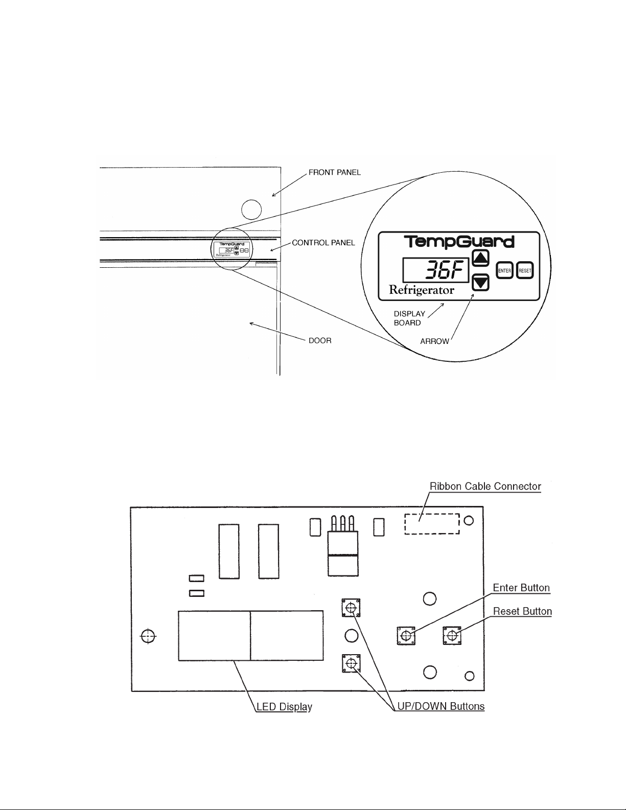
B. Display Board
The display board is located on the right hand side of the control panel between the top
of the door and the front panel. From this area, information regarding the functioning
of the unit can be obtained. When the unit is turned on, the first display reads "r_##",
where "##" indicates the board revision level. From the display board, various electronic
controls and functions can also be adjusted. See "D. Settings and Diagnostics."
Evercheck Display Board
19
 Loading...