

Page 1
Hoshizaki America, Inc.
Hoshizaki
Modular Crescent Cuber
Serenity Series
Model
KMS-1401MLJ
“A Superior Degree
of Reliability”
www.hoshizaki.com
PARTS LIST
Number: 71342
Issued: 8-19-2011
Revised: 8-1-2012
Page 2

CONTENTS
Auxiliary Codes ...................................................................................................................... 3
Note About Ordering Parts .................................................................................................... 3
A. Ice Cuber Assembly and Refrigeration Circuit ................................................................... 4
B. Water Circuit ...................................................................................................................... 7
C. Control Box Assembly ..................................................................................................... 10
D. Label Location ..................................................................................................................11
E. Accessories & Packaging ................................................................................................ 12
2
Page 3

Auxiliary Codes
KMS-1401MLJ A-0 October 2011
B-0 January 2012
Auxiliary Code Breakdown
The auxiliary code is the rst two characters in the serial number. The rst character
indicates the year. Years progress or regress in alphabetical order. The series runs from
"A" through "V" and the letters "I" and "O" are skipped. The second character indicates
signicant part changes within a year. Base is "0" and this number advances for each
change. In cases where there is a letter in parentheses, this designates the month. This is
the last character in the serial number. The series runs from "(A)" through "(M)" and the
letter "(I)" is skipped. This designation is only included when identifying a parts change
within an auxiliary code.
Note About Ordering Parts
Most assemblies cannot be ordered as complete units; parts in the assemblies generally
must be ordered separately.
3
Page 4
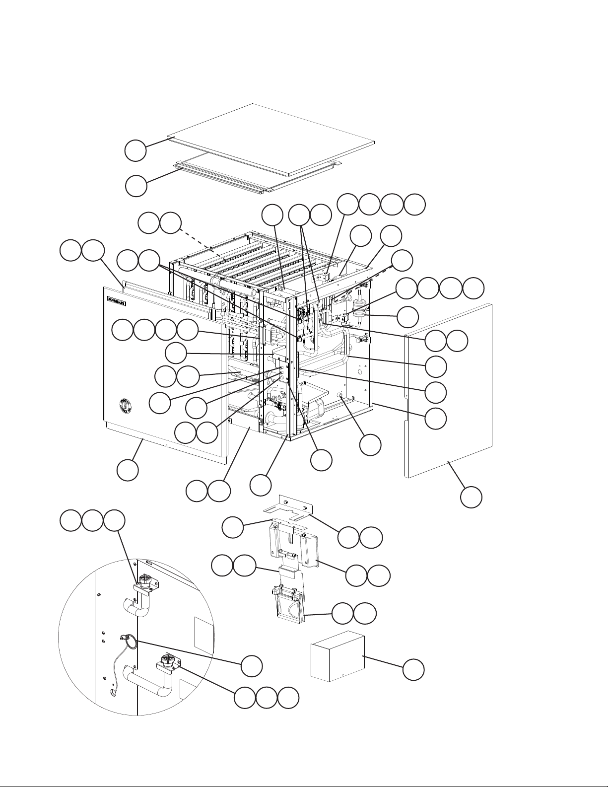
A. Ice Cuber Assembly and Refrigeration Circuit
KMS-1401MLJ
A-0, B-0
15
13
12
12a
24
36
35
29 30
16
6
25
31
18
4
32
18a
8
7
11
9
11a
26
28
33
34
5
39 40
37
10
40a
27
43
38
42
41
40
49
48
3
51
40a
50
41
14
1
4746
23
22
23a
17
1
44
45
19a
19
20a
20
21a
21
2
4
Page 5

Title: A. Ice Cuber Assembly and Refrigeration Circuit Model: KMS-1401MLJ
Index
No. Description
Ice Cuber Assembly
Order Assembly Parts Individually
1 Coupling Bracket 4A3891-02 2
2 Control Box Cover 3A3248-01 1
3 Switch Box Bracket 3A3304-01 1
4 Switch Box Cover 4A3623-01 1
5 Switch Box 3A3277-01 1
6 Control Switch 443119-01 1
7 Service Switch 4A0985-01 1
8 Fuse Holder 4A3449-01 1
9 Fuse 4A0893-07 1
10 Evaporator Case Pipe B 4A3525-01 1
11 Lower Front Frame 4A3542G01 1
11a Thumbscrew 415949G10 2
12 Front Insulation 3A3250G01 1
12a Thumbscrew 415949G10 4
13 Top Insulation 3A3251G01 1
14 Right Side Panel 2A3225G01 1
15 Top Panel 2A3226-01 1
16 Front Panel 2A3236-01 1
17 Wire Harness (KMS-SRK) 469256G01 1
18 Splash Curtain 3A6842-01 1
18a Thumbscrew 415949G08 2
19 Bin Control Bracket 4A4678-01 1
19a Thumbscrew 415949G08 2
20 Bin Control Mount 3A3278G01 1
20a Thumbscrew 415949G08 2
21 Bin Control 2A4393G01 1
21a Thumbscrew 415949G08 2
22 Bin Control Cover 4A3580-01 1
23 Bin Control Extension Bracket 4A4296G01 1
23a Thumbscrew 415949G08 2
Material or
Model Number Part Number
1A2292A01 1
A-0
B-0
Required Number
Refrigeration Circuit
Order Assembly Parts Individually
24 Evaporator (includes item 25) 2A6657G01 1
25 Evaporator Plate HS-0214 1A1514G01 6
26 Side Frame A 2A5022-01 1
27 Side Frame B 3A3256-01 1
28 Upper Front Frame 3A3257-01 1
29 Insulation Holder 3A0979-01 1
30 Rubber Tube 323974-01 1
31 Insulation 436671-02 1
32 Insulation 436597-01 1
33 Thermostatic Expansion Valve 4A1482-01 2
34 Thermostatic Expansion Valve
Cover
1A2302A01 1
3A0944-01 2
5
Page 6

Title: A. Ice Cuber Assembly and Refrigeration Circuit Model: KMS-1401MLJ
Index
No. Description
35 Thermostatic Expansion Valve
Bulb Holder
36 Clamp 443461-02 2
37 Strainer 441569-02 1
38 Liquid Line Valve Body 4A3276-01 1
39 Hot Gas Valve Body 4A3978-01 1
40 Valve Coil (includes item 40a) 4A3277-01 2
40a Bolt 4A3277F01 2
41 Bracket 4A3890-01 2
42 Drier 4A2663-01 1
43 Check Valve 4A1373-01 2
44 Suction Line Coupling 4A3826-01 1
45 Suction Line Tube Holder 438245-02 1
46 Liquid Line Coupling 434072-01 1
47 Liquid Line Tube Holder 438245-01 1
48 Heat Exchanger 3A3263G01 1
49 Thermistor 429006-05 1
50 Thermistor Holder 438247-01 1
51 Rear Panel 2A5016-01 1
Material or
Model Number Part Number
3A0107-01 2
A-0
B-0
Required Number
6
Page 7

B. Water Circuit
KMS-1401MLJ
A-0, B-0
20
42
43
31
61
14
16
45
21
22
37
23
59
17
15
56
39
10
28
19
11
29
38
24
25
13
102855
58
44
12
62
50
46
40
35
32
36
34
53
57
60
35
18
41
47
33
9b
52
30
51
7
48
27
58
54
1
26
49
4
5
9a
8
9
3c
3a
6
3d
Pump Motor Assembly
2
3e
3b
3
7
Page 8

Title: B. Water Circuit Model: KMS-1401MLJ
Index
No. Description
Water Circuit
Order Assembly Parts Individually
1 Pump Motor Assembly
(includes items 2 through 9b)
2 Pump Motor 2U0106-01 1
3 Pump Flange 215662-01 1
3a Hex Head Bolt 6×40, SS 7B02-0640 4
3b Split Lock Washer M6, SS 7L22-0600 4
3c Tooth Washer M6, SS 7R22-0600 2
3d Flat Washer M6, SS 7W22-0600 4
3e Hex Nut M6, SS 7N12-0600 4
4 Pump Motor Bracket 3A3252-01 1
5 Mechanical Seal 4A3820-01 1
6 Packing 428547-01 1
7 Impeller 436584-01 1
8 Pin 4A0648-01 1
9 Pump Housing 2A3214-01 1
9a Hex Head Bolt 4×55, SS 7B02-0455 4
9b Hex Flange Nut M4, SS 7J02-0400 4
10 Water Valve Bracket 3A5725-01 2
11 Inlet Water Valve 4A5251-04 1
12 Water Supply Pipe 3A5118G01 1
13 Rubber Gasket 413854-03 2
14 Distributor A 4A3528-01 1
15 Distributor B 3A3239-01 1
16 Distributor C 4A3530-01 1
17 Flange 439267-02 1
18 Flange 439267-03 2
19 Flange 4A3573-01 1
20 Distributor Hose A 325738-01 1
21 Distributor Hose B 325738-02 1
22 Distributor Hose C 325739-02 2
23 Joint Pipe 439297-02 1
24 Spray Tube 437049G04 6
25 Spray Guide 2A4282-03 6
26 Pump Drain 3A5841G01 1
27 Drain Pipe 4A3568G01 1
28 Water Valve (drain and wash) 4A3722-05 2
29 Drain Valve Bracket A 4A3569-01 1
30 Drain Valve Bracket B 4A3570-01 1
31 Tank 1A2291G01 1
32 Suction Hose A 3A3234-01 1
33 Suction Hose B 4A3534-01 1
34 Evaporator Case Pipe A 4A3524-01 1
35 Evaporator Case Pipe C 4A3526-01 2
36 Evaporator Case Pipe D 4A3527-01 1
37 Evaporator Case Pipe E 4A3765-01 1
38 Upper Inlet Hose 3A3496-01 1
39 Outlet Hose 3A3497-01 1
Material or
Model Number Part Number
1A2290A01 1
HS-0183 2A3237A01 1
Required Number
A-0
B-0
8
Page 9

Title: B. Water Circuit Model: KMS-1401MLJ
Index
No. Description
40 Overow Drain Hose 4A3536-01 1
41 Overow Cap 2A3215-01 1
42 Cube Guide 1A0966-01 2
43 Tank Separator 2A3220-01 1
44 Discharge Hose A 4A3532-01 1
45 Discharge Hose B 4A3533-01 1
46 Lower Inlet Hose 4A3535-01 1
47 Drain Hose A 4A3537-01 1
48 PVC Pipe 433509-03 1
49 Drain Hose B 434808-01 1
50 Pump Motor Cover 4A3586-01 1
51 Float Switch 4A3624-01 1
52 Float Switch Connector 3A4169-01 1
53 Pipe Stopper 4A3767-01 1
54 Float Switch Hose 4A4851-01 1
55 Water Valve 4A5251-05 1
56 Vinyl Hose L=40 7716-1216 1
57 Vinyl Hose L=80 7716-1216 1
58 Vinyl Hose L=50 7716-1519 2
59 Vinyl Hose L=320 7716-1519 1
60 Vinyl Hose L=45 7716-1519 1
61 Vinyl Hose L=124 7716-2732 1
62 Silicone Hose L=320 7730I3812 1
Hose Clamp 25mm, SS 427443-03 3
Hose Clamp 16.5mm, SS 427443-04 1
Hose Clamp 18mm, SS 427443-05 7
Hose Clamp 20mm, SS 427443-06 4
Hose Clamp 13.5mm, SS 427443-07 6
Hose Clamp 27mm, SS 427443-08 1
Hose Clamp 32mm, SS 427443-09 8
Material or
Model Number Part Number
Hose Clamps
Required Number
A-0
B-0
9
Page 10

C. Control Box Assembly
KMS-1401MLJ
A-0, B-0
2
1
8
7
3
X10 X12
X11 X13
6
4
5
9
Title: C. Control Box Assembly Model: KMS-1401MLJ
Index
No. Description
Control Box Assembly
Order Assembly Parts Individually
1 "G" Control Board 2A3792-01 1
2 Control Board Support 4A0336-03 4
3 Terminal Block 4A4201-01 1
4 Pump Motor Capacitor 10MFD,
5 X10, X11, X12, X13 Relay 406132-07 4
6 Control Transformer 3A0172-01 1
7 Ground Screw 433304-02 1
8 Square Washer 433537-02 1
9 Wire Harness 4A2200G04 1
Material or
Model Number Part Number
3A3247A01 1
443192-01 1
250VAC
10
Required Number
A-0
B-0
Page 11

D. Label Location
KMS-1401MLJ
A-0, B-0
1
5
12
10
2
9
3
8
11
13
Title: D. Label Location Model: KMS-1401MLJ
Index
No. Description
Label Location
Order Assembly Parts Individually
1 Emblem 4A0560-01 1
2 Penguin Label 4A0526-01 1
3 Maintenance Label 2A3296-01 1
4 Warning Label K 4A4736-01 1
5 Instruction Label 444575-01 1
6 Manual Label 3A3331-01 1
7 Fuse Label 4A2817-01 1
8 Caution Label 4A4209-01 1
9 Alarm Label 4A3517-01 1
10 Control Board Label 3A4784-01 1
11 Caution 4A5356-01 1
12 Nameplate 3A6835-01 1
13 Rating Label 3A6836-01 1
14 Wiring Label 3A6637-01 1
14
4
Material or
Model Number Part Number
2A4558A04 1
6
7
Required Number
A-0
B-0
11
Page 12

E. Accessories & Packaging
KMS-1401MLJ
A-0, B-0
Title: E. Accessories & Packaging Model: KMS-1401MLJ
Index
No. Description
1 Instruction Manual 91A1YH10A 1
2 Universal Brace 4A0363-01 2
2a Hex Head Bolt 5×12, SS 7B02-0512 2
3 Sealant RTV-748 8 601- 0111 1
Packaging 2A5858A02
Material or
Model Number Part Number
Required Number
A-0
B-0
12
 Loading...