

Page 1

NO.:
ISSUED:
REVISED:
73085
AUG. 18, 1999
JAN. 13, 2004
HOSHIZAKI
MODULAR CRESCENT CUBER
MODELS
KML “F” SERIES
KML “H” SERIES
SERVICE MANUAL
Page 2

IMPORTANT
Only qualified service technicians should attempt to service or maintain this icemaker.
No service or maintenance should be undertaken until the technician has thoroughly
read this Service Manual.
HOSHIZAKI provides this manual primarily to assist qualified service technicians in the
service and maintenance of the icemaker.
Should the reader have any questions or concerns which have not been satisfactorily
addressed, please call or write to the HOSHIZAKI Technical Support Department for
assistance.
HOSHIZAKI AMERICA, INC.
618 Highway 74 South
Peachtree City , GA 30269
Attn: HOSHIZAKI T echnical Support Department
Phone: 1-800-233-1940 T echnical Service
(770) 487-2331
Fax: (770) 487-3360
NOTE: T o expedite assistance, all correspondence/communication MUST include the following
information:
• Model Number
• Serial Number
• Complete and detailed explanation of the problem
2
Page 3

• Please review this manual. It should be read carefully before the icemaker is serviced
or maintenance operations performed. Only qualified service technicians should service
and maintain the icemaker. This manual should be made available to the technician
prior to service or maintenance.
CONTENTS
PAGE
I. SPECIFICATIONS.........................................................................................................................6
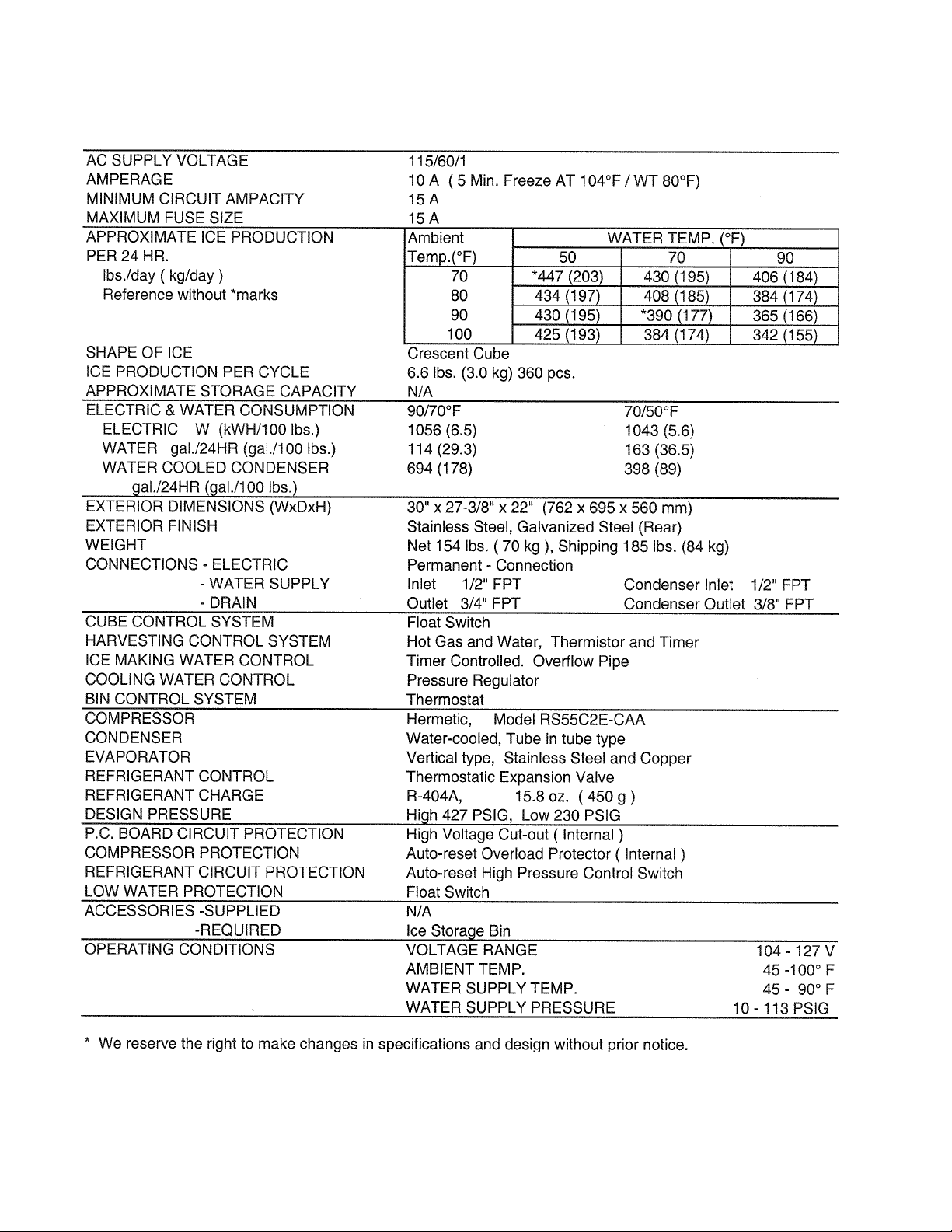
1. KML-250MAH (Air-cooled) .................................................................................................... 6
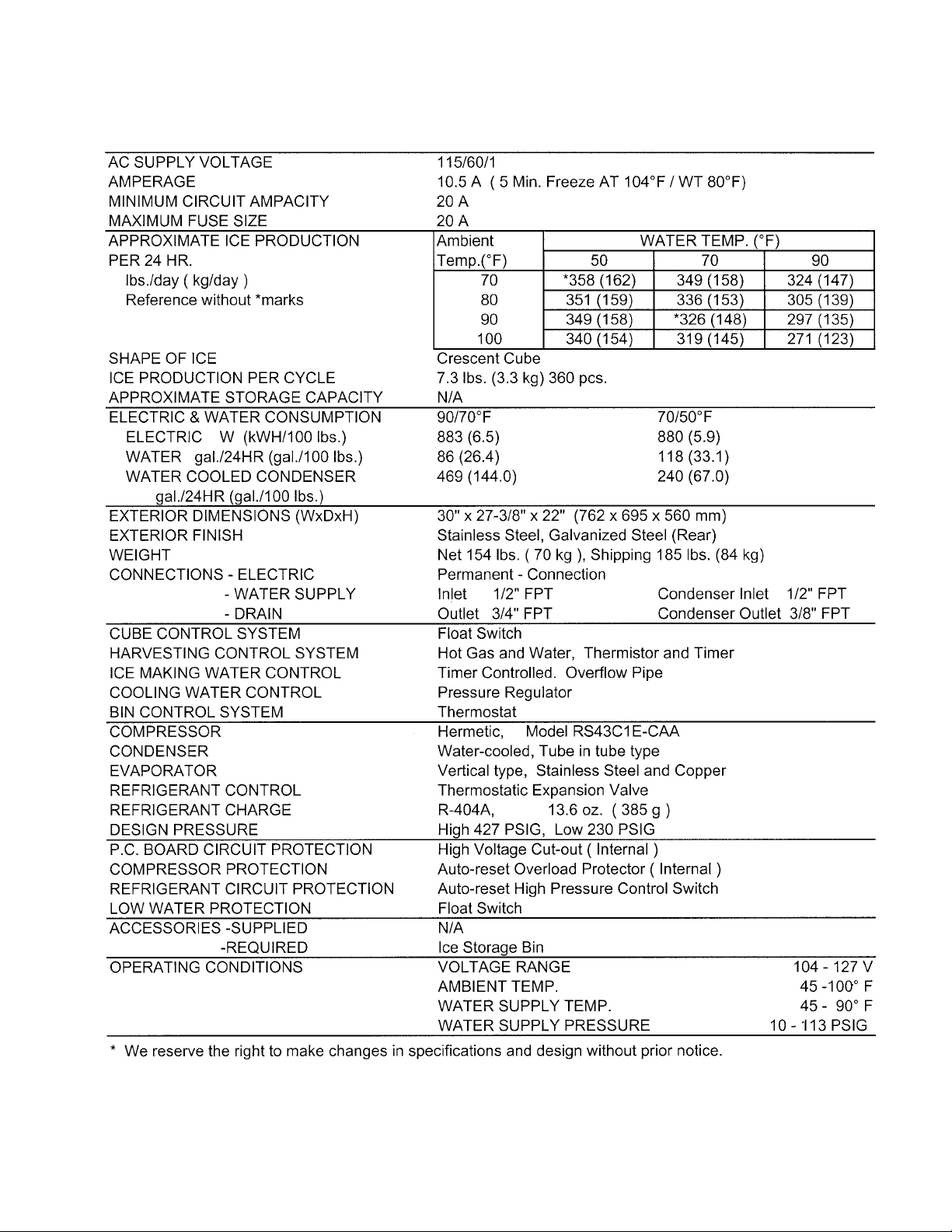
2. KML-250MWH (Water-cooled) ............................................................................................. 7
3. KML-350MAF (Air-cooled) ....................................................................................................8
KML-350MWF (Water-cooled) .............................................................................................. 9
4.
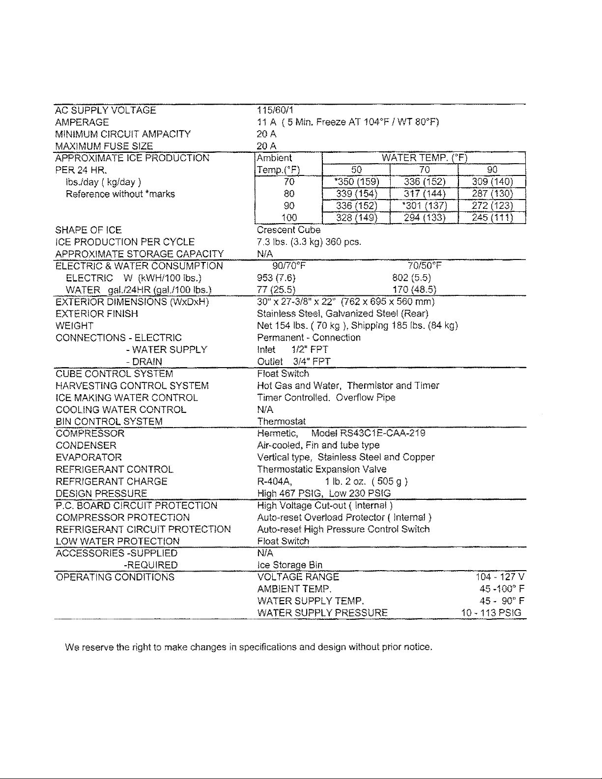
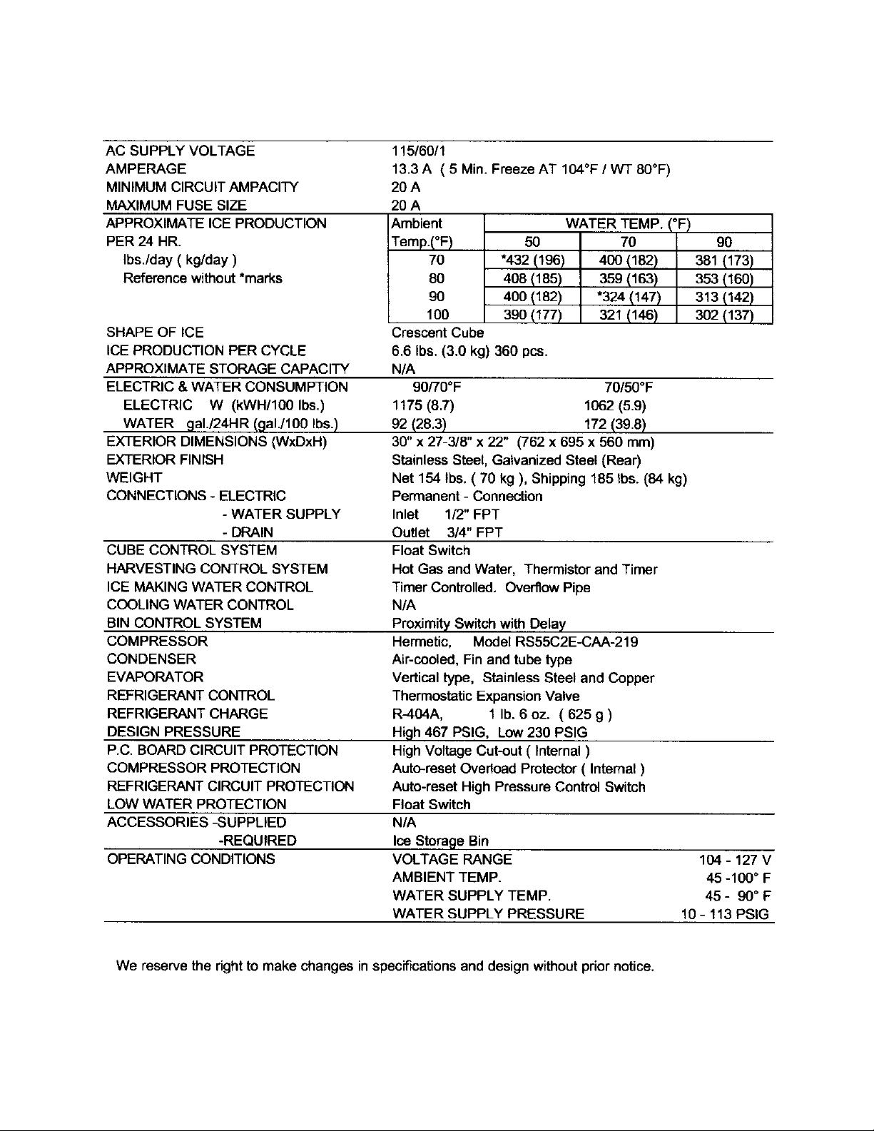
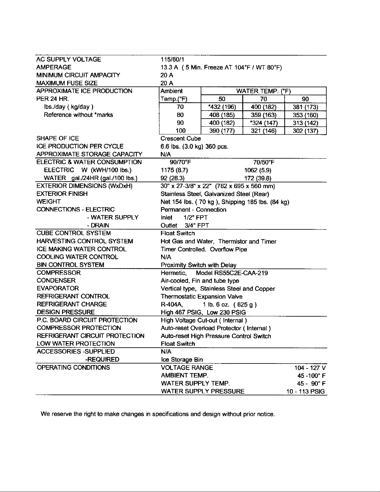
5. KML-350MAH (Air-cooled) ..................................................................................................10
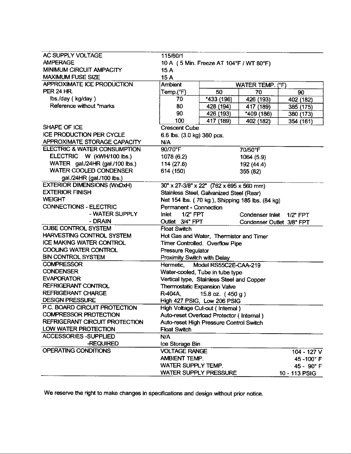
6. KML-350MWH (Water-cooled; Serial #L00001J through M20060C) .................................11
7.
KML-350MWH (Beginning Serial #M30061E) ....................................................................12
8. KML-450MAF (Air-cooled) ..................................................................................................13
KML-450MWF (Water-cooled) ............................................................................................ 14
9.
10. KML-450MAH (Air-cooled) ..................................................................................................15
11. KML-450MWH (Water-cooled; Serial #L00001D through M10530B).................................16
12. KML-450MWH (Beginning Serial #M20531D) ....................................................................17
13. KML-600MAF (Air-cooled) ..................................................................................................18
14.
KML-600MWF (Water-cooled)............................................................................................ 19
15.
KML-600MRF (Remote air-cooled) ....................................................................................20
16. KML-600MAH (Air-cooled) ..................................................................................................21
17.
KML-600MWH (Water-cooled; Serial #L00001D through M10115C) ..................................22
18. KML-600MWH (Water-cooled; Beginning Serial #M10121E)..............................................23
19.
KML-600MRH (Remote air-cooled) .....................................................................................24
20.
CONDENSER UNIT, URC-7F .............................................................................................25
II. GENERAL INFORMATION .........................................................................................................27
1. CONSTRUCTION................................................................................................................27
[a] KML-250MAH, KML-350MAF, KML-350MAH, KML-450MAF, KML-450MAH....................27
[b]
KML-250MWH, KML-350MWF, KML-350MWH, KML-450MWF, KML-450MWH .................
[c] KML-600MAF, KML-600MAH ..........................................................................................29
[d] KML-600MWF, KML-600MWH .......................................................................................30
[e] KML-600MRF, KML-600MRH .........................................................................................31
2. CONTROLLER BOARD .......................................................................................................32
[a] SOLID-STATE CONTROL.............................................................................................32
[b] CONTROLLER BOARD ................................................................................................ 32
[c] SEQUENCE................................................................................................................... 36
[d] CONTROLS AND ADJUSTMENTS ...............................................................................39
[e] CHECKING CONTROLLER BOARD ...........................................................................43
3. SWITCHES ..........................................................................................................................44
4. MECHANICAL BIN CONTROL ..............................................................................................45
PROXIMITY SWITCH.....................................................................................................45
[a]
[b] EXPLANATION OF OPERATION .................................................................................46
[c]
TROUBLESHOOTING ..................................................................................................46
28
3
Page 4

III. TECHNICAL INFORMATION........................................................................................................47
1. WATER CIRCUIT AND REFRIGERANT CIRCUIT..................................................................47
[a] AIR-COOLED MODELS ...................................................................................................47
[b] WATER-COOLED MODELS ............................................................................................ 48
[c] REMOTE AIR-COOLED MODELS...................................................................................49
2. WIRING DIAGRAMS ................................................................................................................50
[a] KML-250MAH (Beginning Serial #L00001E, ending Serial #M10460F);.................................
KML-250MWH (Beginning Serial #L10001K, ending Serial #M10090D) ...........................50
[b] KML-250MAH (Beginning Serial #M20461G); ........................................................................
KML-250MWH (Beginning Serial #M20091G) ...................................................................51
[c]
KML-350MAF, KML-350MWF............................................................................................52
[d] KML-350MAH (Beginning Serial #L00001L, ending Serial #M10290F);.................................
KML-350MWH (Beginning Serial #L00001J, ending Serial #M30080F) ............................53
[e] KML-350MAH (Beginning Serial #M20291G); .......................................................................
KML-350MWH (Beginning Serial #M40081G) ...................................................................54
[f]
KML-450MAF, KML-450MWF ............................................................................................55
[g] KML-450MAH (Beginning Serial #L00101C, ending Serial #L00950G); ................................
KML-450MWH (Beginning Serial #L00001D, ending Serial #L00200G)............................56
[h] KML-450MAH (Beginning Serial #L20951H, ending Serial #M12770F); ................................
KML-450MWH (Beginning Serial #L10201H, ending Serial #M20710F)............................57
[i]
KML-450MAH (Beginning Serial #M22771G); .......................................................................
KML-450MWH (Beginning Serial #M30711G)...................................................................57
[j]
KML-600MAF, KML-600MWF, KML-600MRF.....................................................................59
[k] KML-600MAH (Beginning Serial #L00001F, ending Serial #L00070F);..................................
KML-600MWH (Beginning Serial #L00001D, ending Serial #L00080E)................................
KML-600MRH (Beginning Serial #L00001F, ending Serial #L00050F)..............................60
[l]
KML-600MAH (Beginning Serial #L10071H, ending Serial #M10460G); ................................
KML-600MWH (Beginning Serial #L10081K, ending Serial #M10140E) ...............................
KML-600MRH (Beginning Serial #L10051H, ending Serial #M10350E) ............................61
[m]
KML-600MAH (Beginning Serial #M2_ _ _ _ _); ....................................................................
KML-600MWH (Beginning Serial #M20141F) .......................................................................
KML-600MRH (Beginning Serial #M20331E) ....................................................................62
3. TIMING CHART........................................................................................................................63
4. PERFORMANCE DATA ..........................................................................................................65
[a] KML-250MAH ....................................................................................................................65
[b]
KML-250MWH ...................................................................................................................66
[c]
KML-350MAF .....................................................................................................................67
[d]
KML-350MWF ...................................................................................................................68
[e]
KML-350MAH.....................................................................................................................69
[f]
KML-350MWH (Serial #L00001J through M20060C) .........................................................70
[g]
KML-350MWH (Beginning Serial #M30061E) ....................................................................71
4
Page 5

[h]
KML-450MAF .....................................................................................................................72
[i]
KML-450MWF ...................................................................................................................73
[j]
KML-450MAH ....................................................................................................................74
[k]
KML-450MWH (Serial #L00001D through M10530B) .......................................................75
[l]
KML-450MWH (Beginning Serial #M20531D)...................................................................76
[m]
KML-600MAF ....................................................................................................................77
[n] KML-600MWF ...................................................................................................................78
[o] KML-600MRF.....................................................................................................................79
[p]
KML-600MAH.....................................................................................................................80
KML-600MWH (Serial #L00001D through M10115C) ........................................................81
[q]
[
r ]
KML-600MWH (Beginning Serial #M10121E)....................................................................82
[s]
KML-600MRH ....................................................................................................................83
IV. SERVICE DIAGNOSIS ................................................................................................................84
1. NO ICE PRODUCTION ...........................................................................................................84
2. EVAPORATOR IS FROZEN UP..............................................................................................87
3. LOW ICE PRODUCTION........................................................................................................87
4. ABNORMAL ICE ......................................................................................................................88
5. OTHERS .................................................................................................................................89
V. REMOVAL AND REPLACEMENT OF COMPONENTS...............................................................89
1. SERVICE FOR REFRIGERANT LINES ..................................................................................89
[a] REFRIGERANT RECOVERY ...........................................................................................89
[b] EVACUATION AND RECHARGE [R-404A].......................................................................89
2. BRAZING .................................................................................................................................90
REMOVAL AND REPLACEMENT OF COMPRESSOR .........................................................91
3.
4. REMOVAL AND REPLACEMENT OF DRIER.........................................................................92
5. REMOVAL AND REPLACEMENT OF EXPANSION VALVE....................................................93
6. REMOVAL AND REPLACEMENT OF HOT GAS VALVE AND....................................................
LINE VALVE ............................................................................................................... .............94
7. REMOVAL AND REPLACEMENT OF EVAPORATOR ...........................................................96
8. REMOVAL AND REPLACEMENT OF WATER-REGULATING VALVE ....................................
- WATER COOLED MODEL ONLY ......................................................................................97
9. ADJUSTMENT OF WATER-REGULATING VALVE ..................................................................
- WATER COOLED MODEL ONLY ......................................................................................98
10. REMOVAL AND REPLACEMENT OF CONDENSING PRESSURE .........................................
REGULATOR (C.P.R.) - REMOTE AIR-COOLED MODEL ONLY ........................................99
11. REMOVAL AND REPLACEMENT OF THERMISTOR ...........................................................100
12. REMOVAL AND REPLACEMENT OF FAN MOTOR..............................................................101
13. REMOVAL AND REPLACEMENT OF WATER VALVE..........................................................102
14. REMOVAL AND REPLACEMENT OF PUMP MOTOR ..........................................................103
15. REMOVAL AND REPLACEMENT OF SPRAY TUBES..........................................................103
VI. CLEANING AND MAINTENANCE INSTRUCTIONS...................................................................104
1. PREPARING THE ICEMAKER FOR LONG STORAGE........................................................104
2. CLEANING PROCEDURE ....................................................................................................106
3. SANITIZING PROCEDURE ...................................................................................................108
4. MAINTENANCE......................................................................................................................109
5
Page 6
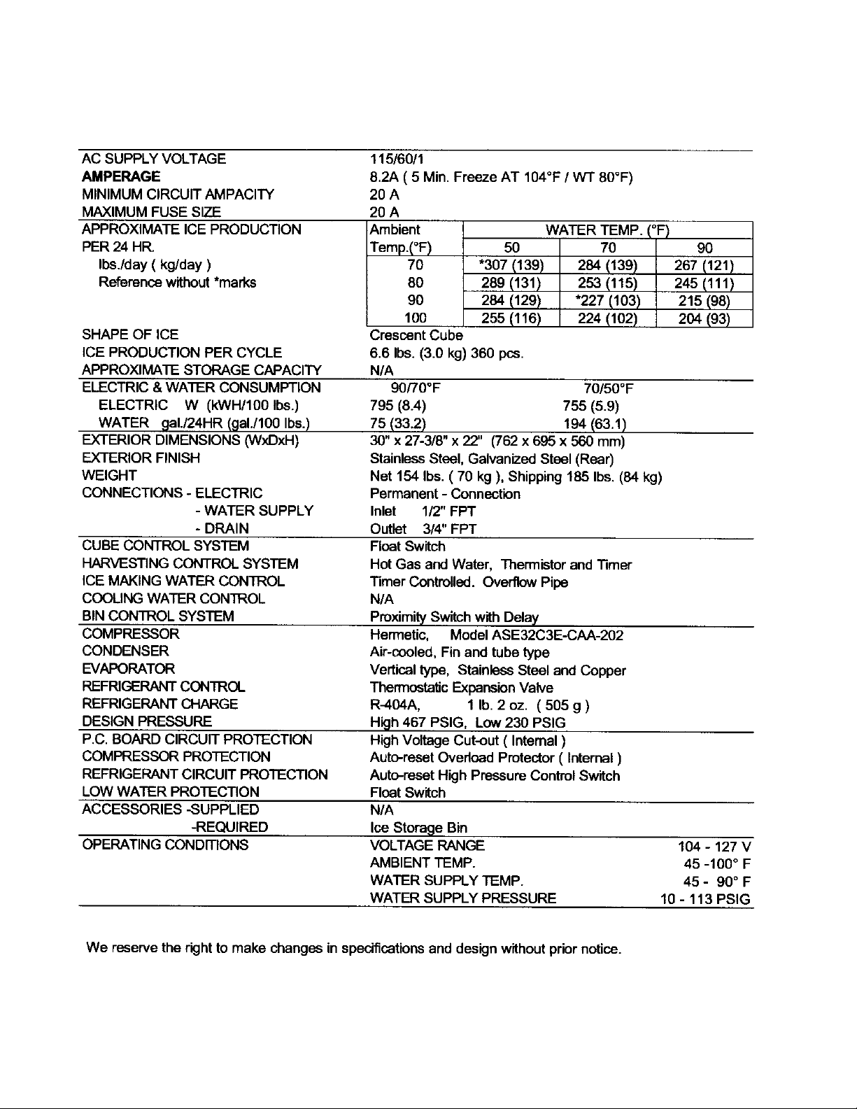
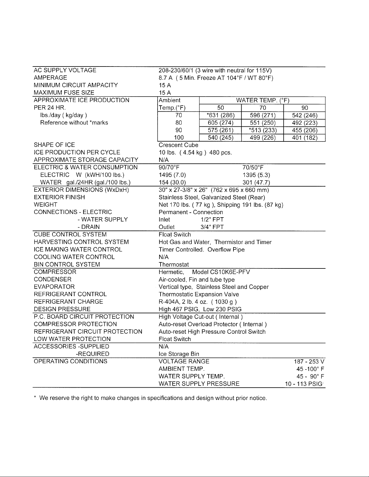
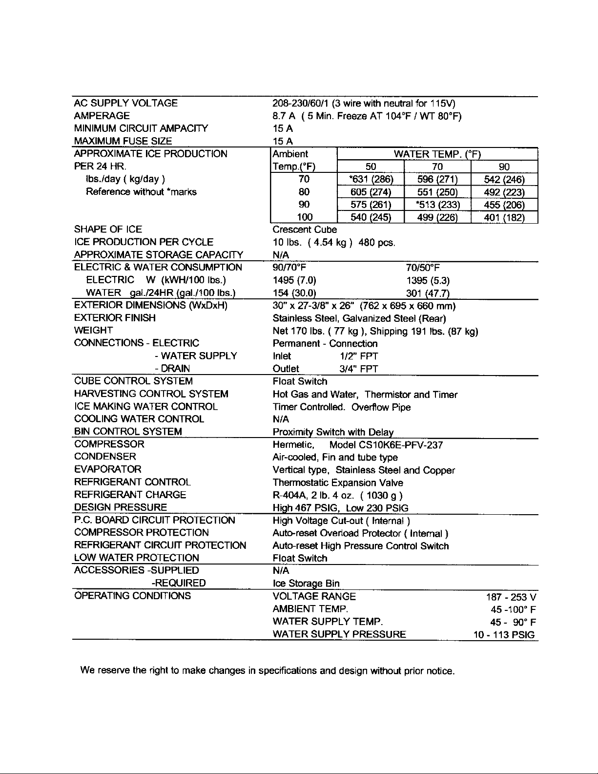
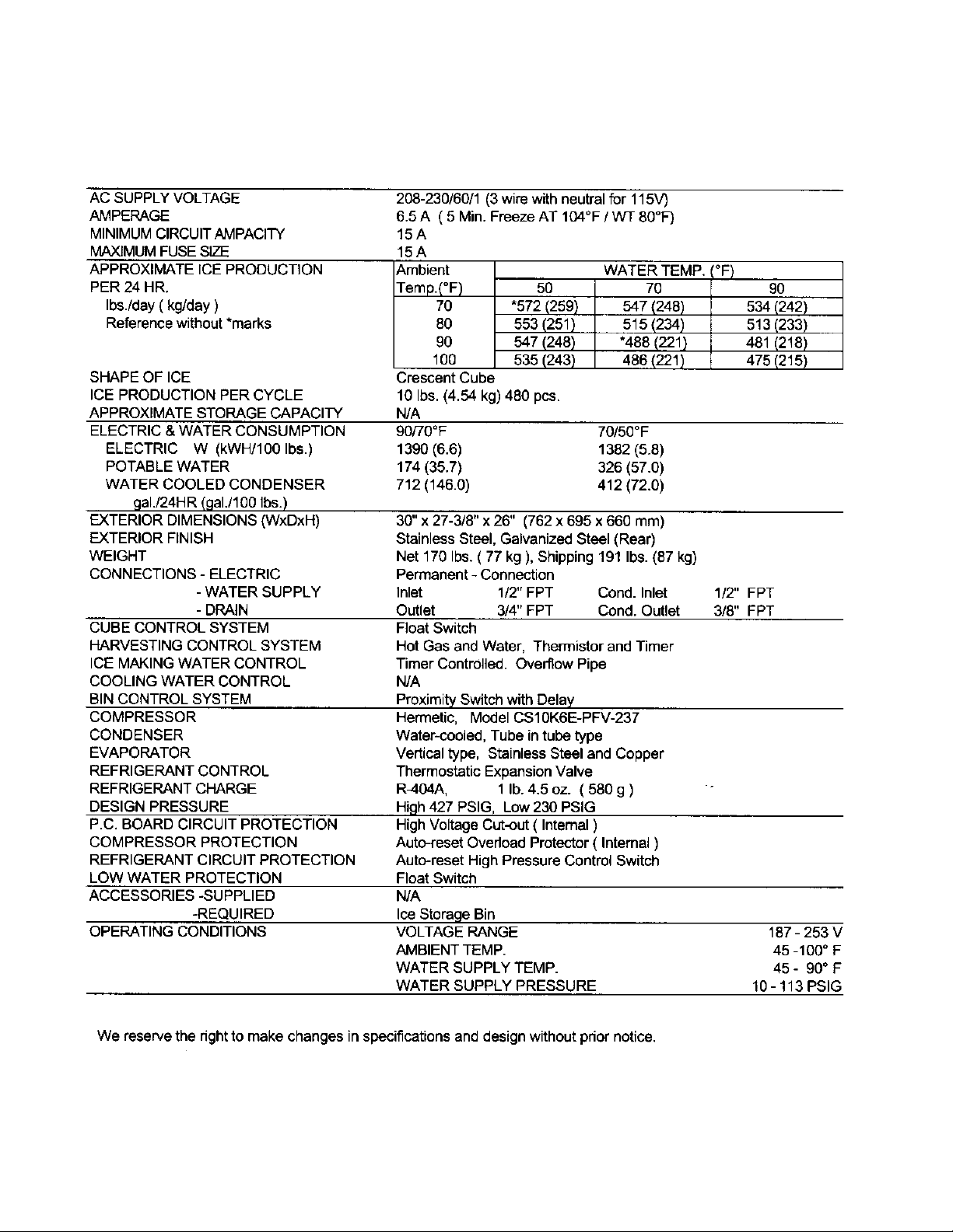
I. SPECIFICATIONS
1. KML-250MAH
6
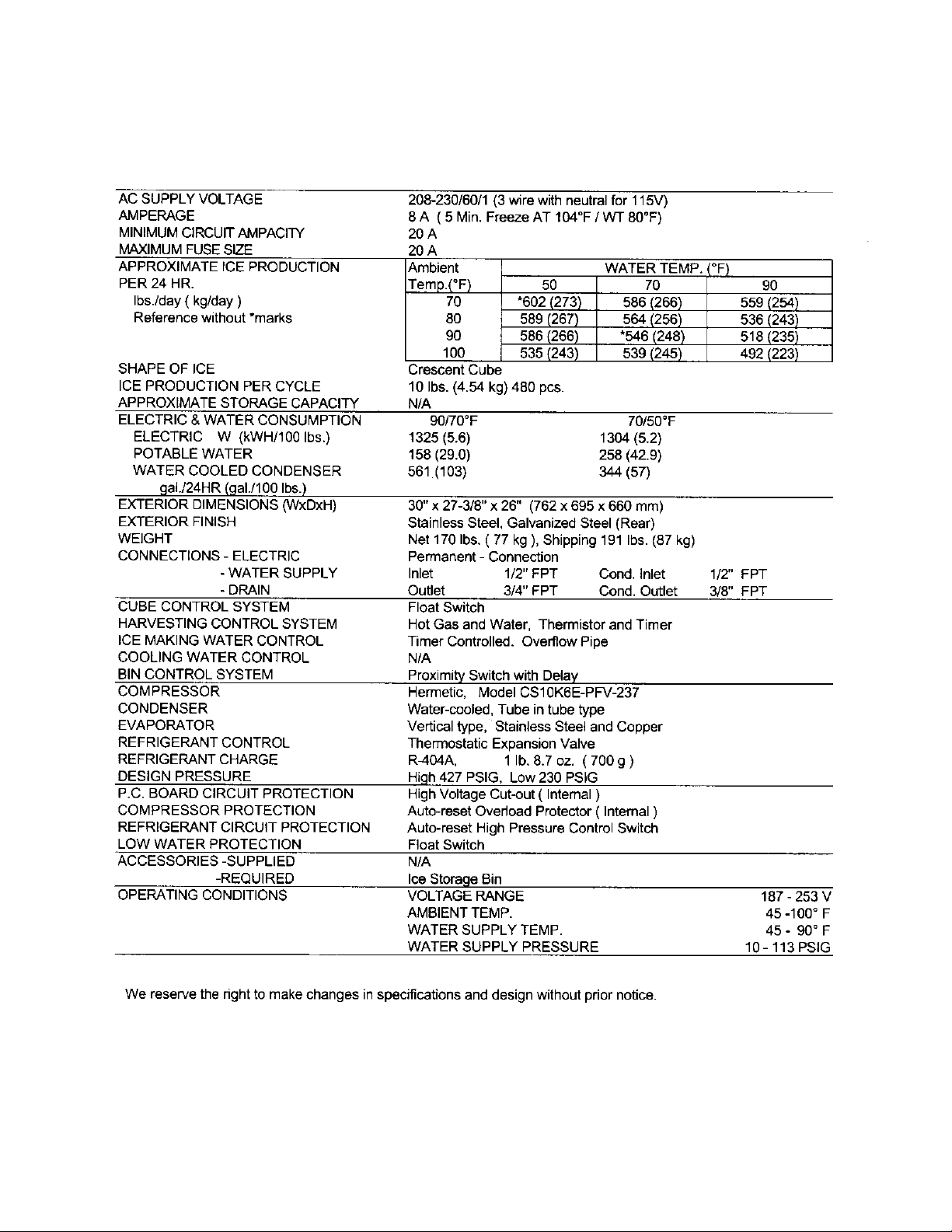
Page 7
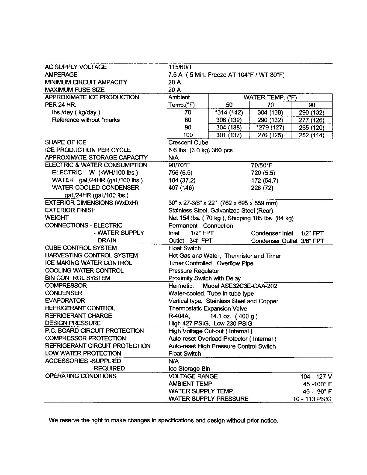
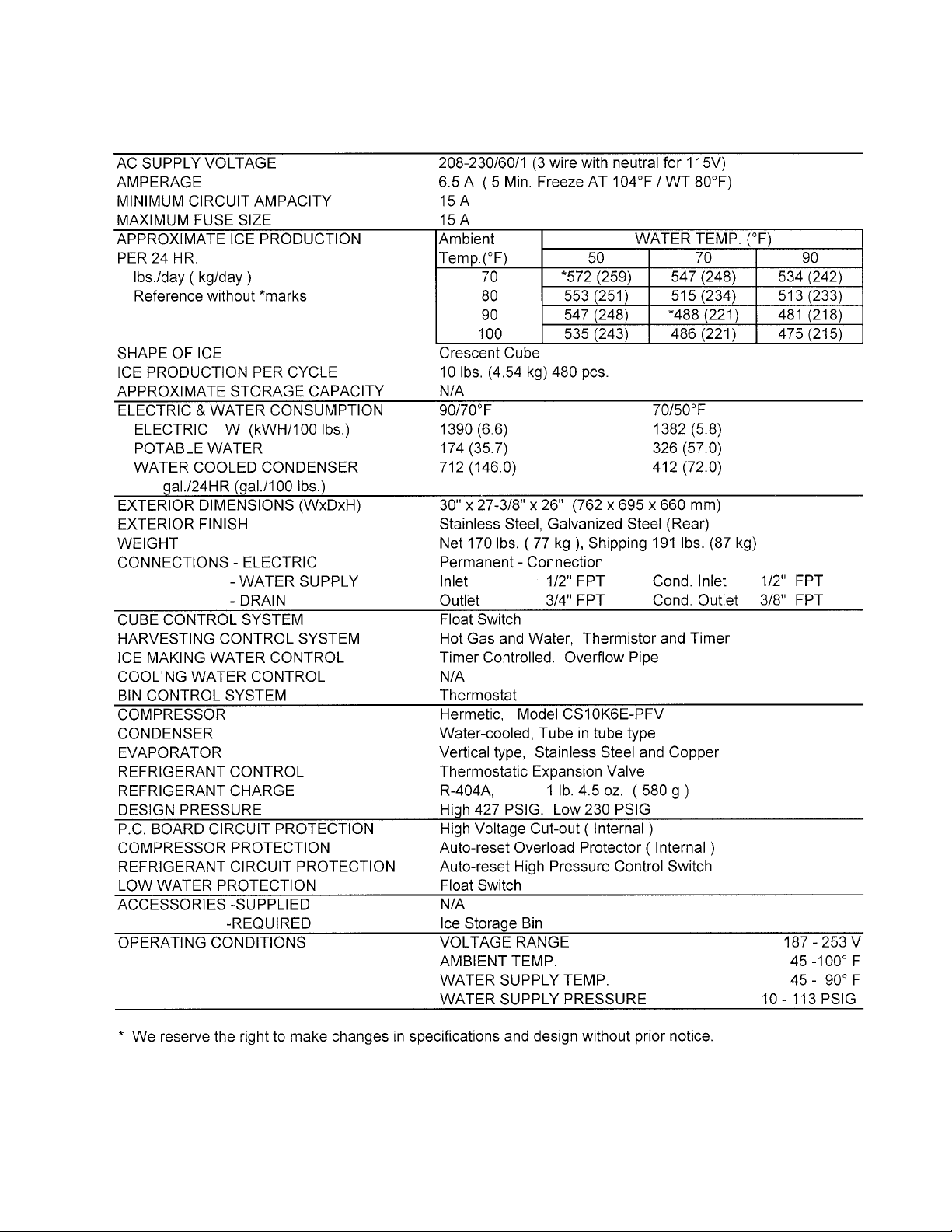
2. KML-250MWH
7
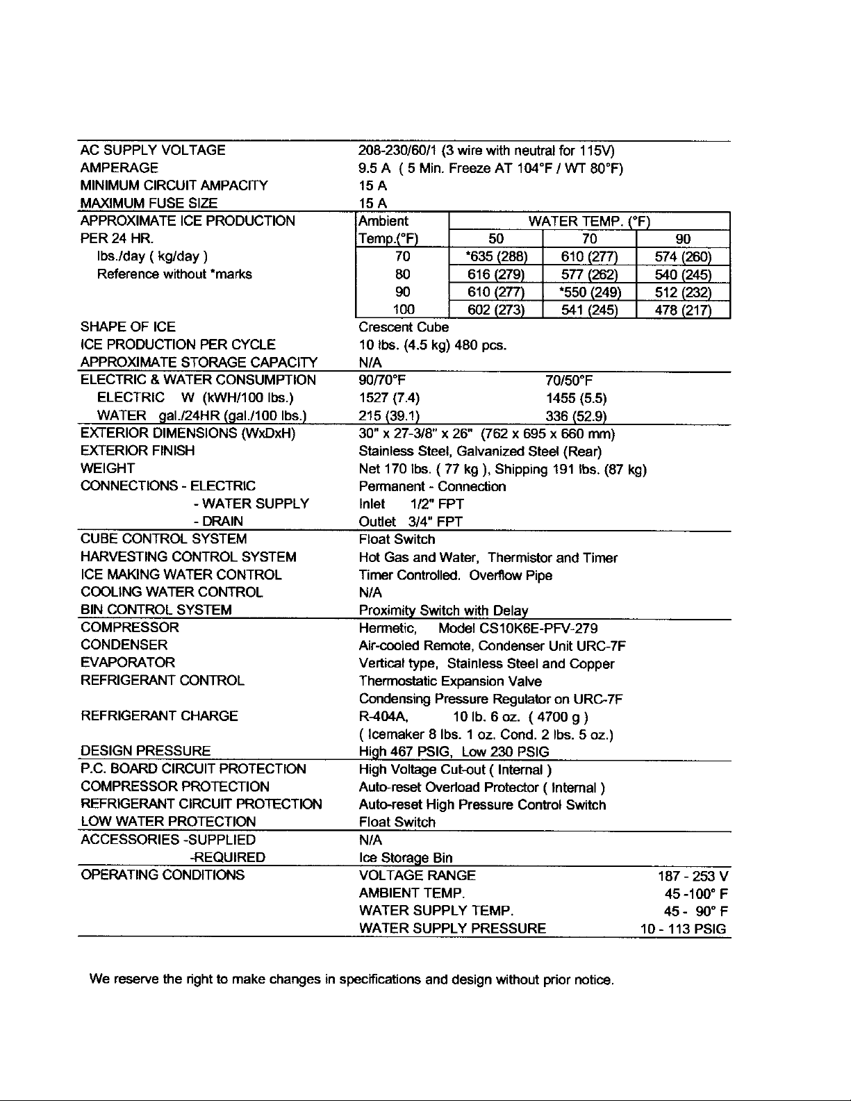
Page 8
3. KML-350MAF
8
Page 9
4. KML-350MWF
9
Page 10
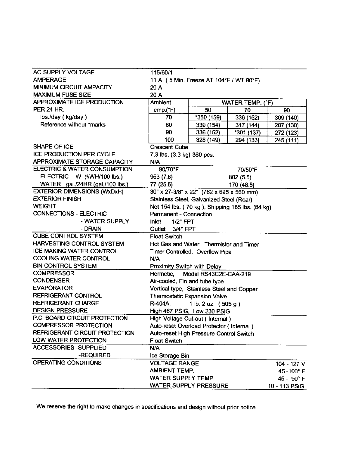
5. KML-350MAH
10
Page 11
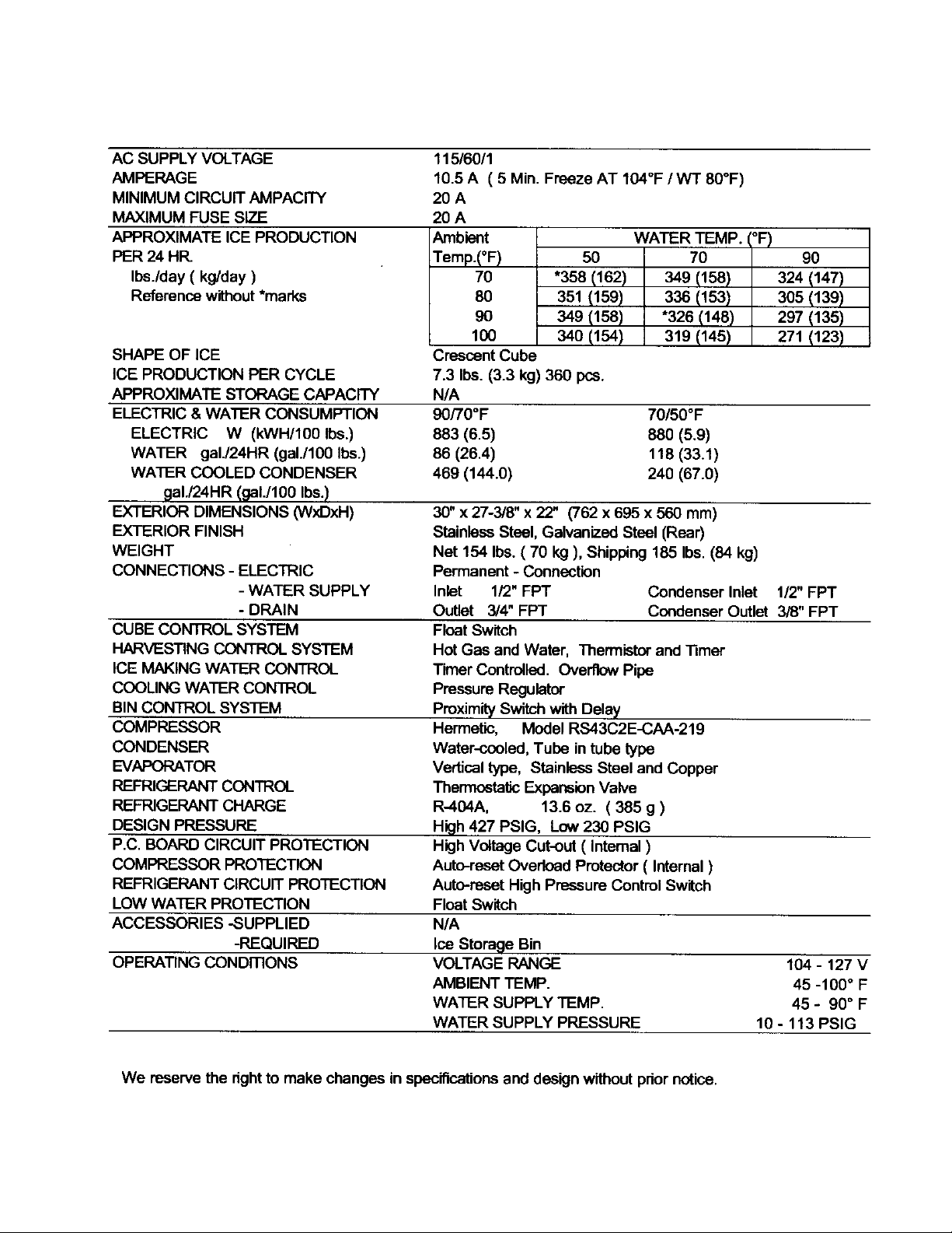
6. KML-350MWH (Beginning serial #L00001J, ending Serial #M20060C)
11
Page 12
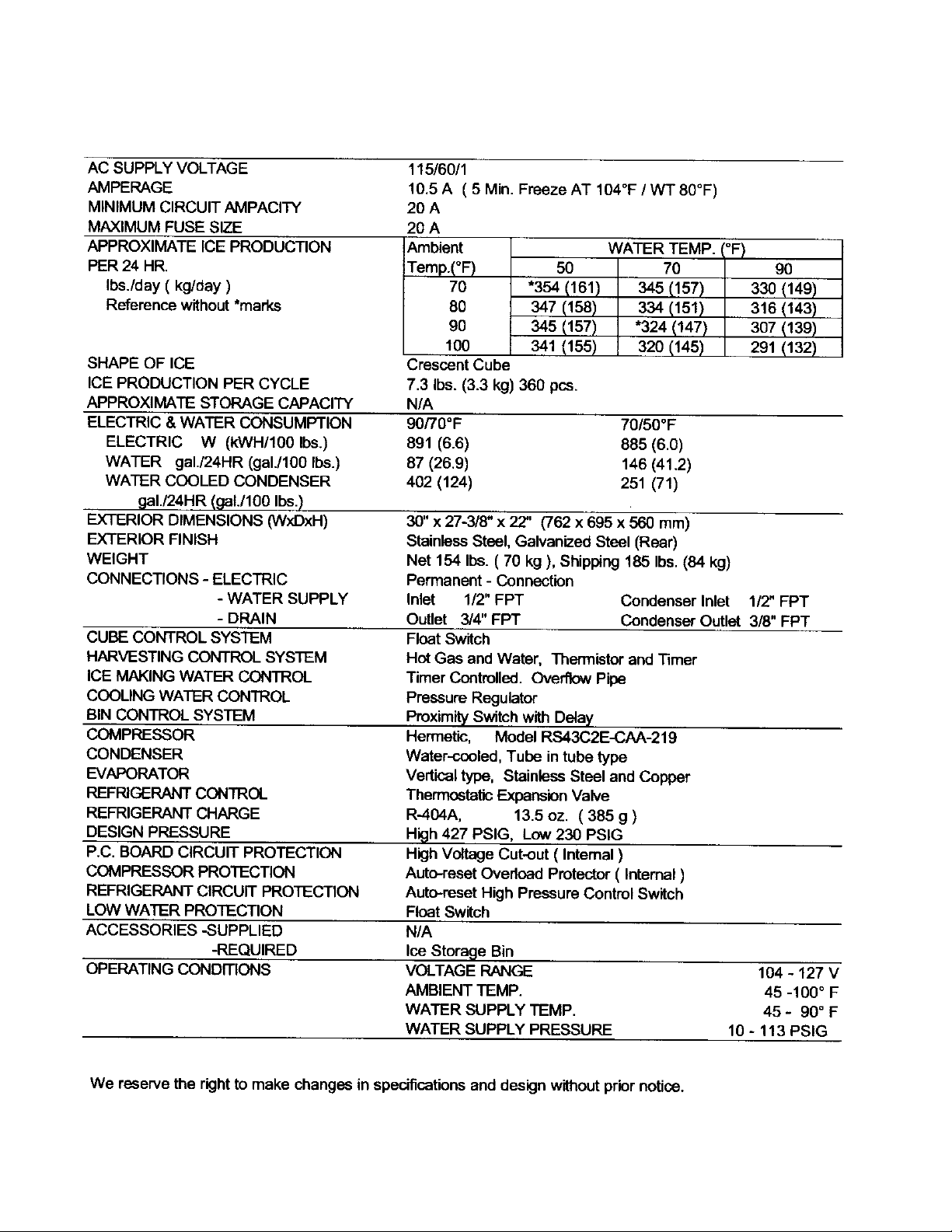
7. KML-350MWH (Beginning serial #M30061E)
12
Page 13
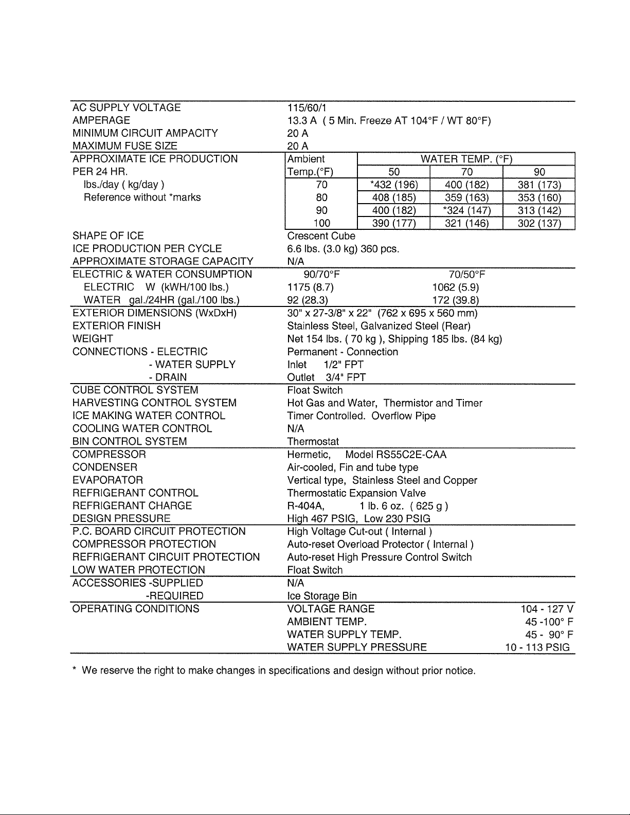
8. KML-450MAF
13
Page 14
9. KML-450MWF
14
Page 15
10. KML-450MAH
15
Page 16
11. KML-450MWH (Beginning Serial #L00001D, ending Serial #M10530B)
16
Page 17
12. KML-450MWH (Beginning Serial #M20531D)
17
Page 18
13. KML-600MAF
18
Page 19
14. KML-600MWF
19
Page 20
15. KML-600MRF
20
Page 21
16. KML-600MAH
21
Page 22
17. KML-600MWH (Beginning Serial #L00001D, ending Serial #M10115C)
22
Page 23
18. KML-600MWH (Beginning Serial # M10121E)
23
Page 24
19. KML-600MRH
24
Page 25
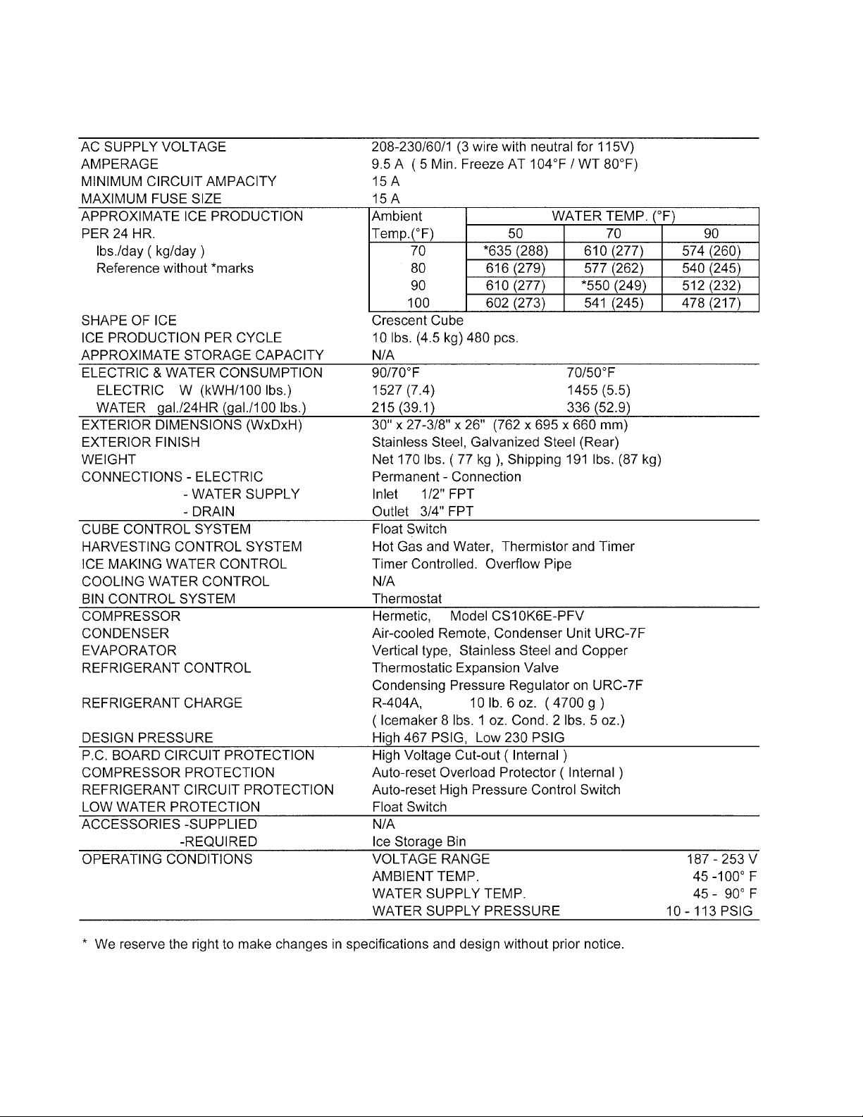
20. CONDENSER UNIT
URC-7F
Unit: mm. (inches)
25
Page 26
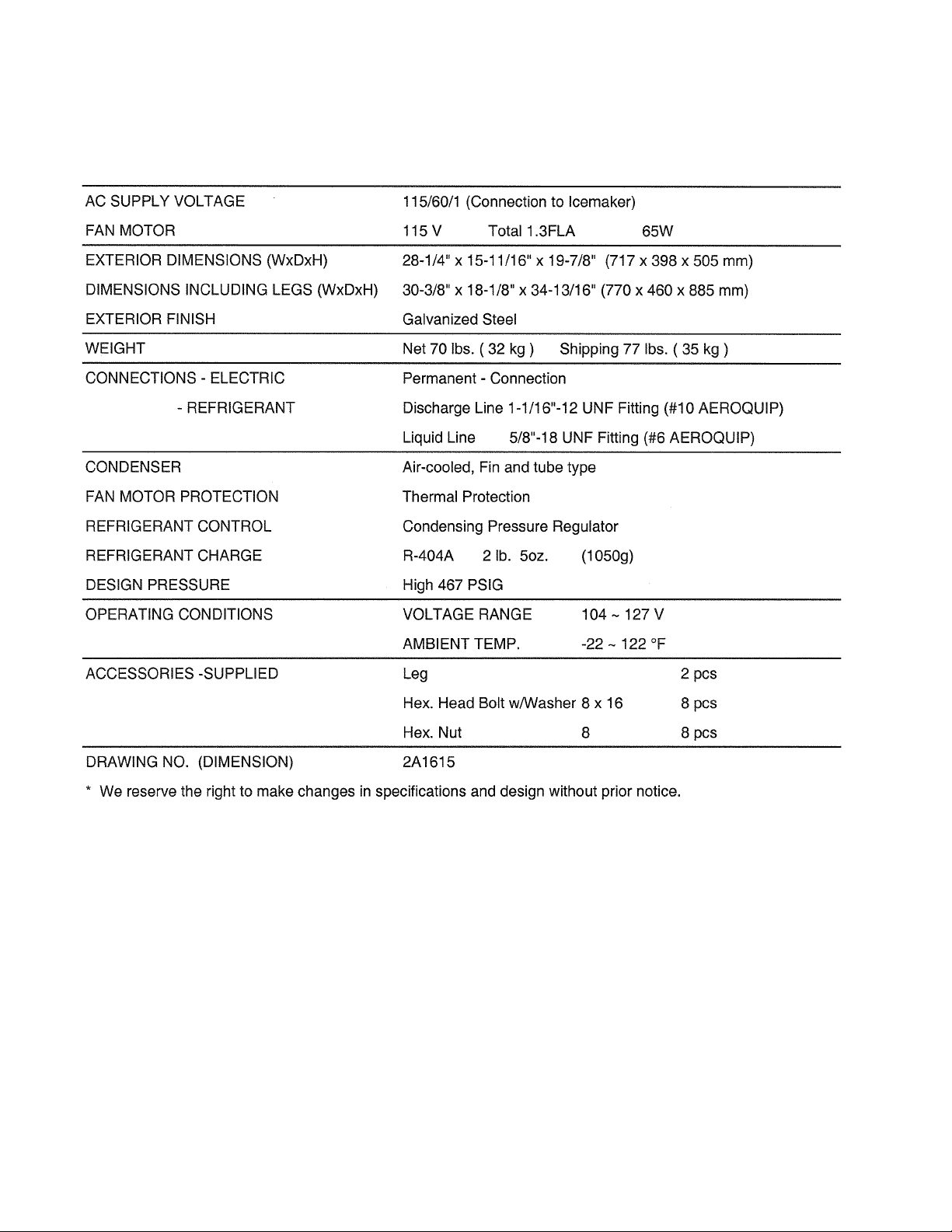
SPECIFICATIONS
URC-7F
26
Page 27
II. GENERAL INFORMATION
1. CONSTRUCTION
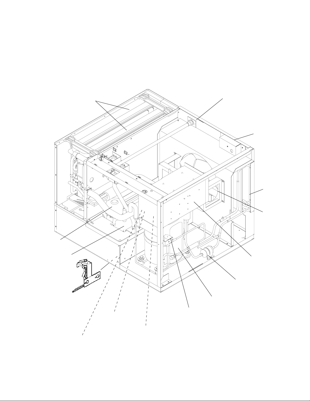
[a] KML-250MAH, KML-350MAF, KML-350MAH, KML-450MAF, KML-450MAH
Water Pump
Spray Tubes
Water Supply
Inlet
Junction Box
Condenser
Condenser
Fan Motor
Float Switch
Mechanical
Bin Control
(except models
with Thermostat)
Control
Switch
Control Box
Drier
Compressor
Hot Gas Valve
Expansion
Valve
Bin Control
Thermostat
(except models with
Mechanical Bin Control)
27
Page 28

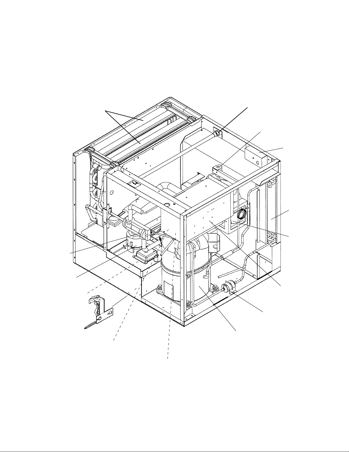
[b] KML-250MWH, KML-350MWF, KML-350MWH, KML-450MWF, KML-450MWH
Spray Tubes
Water Supply
Inlet
Water
Regulator
Junction Box
Water Pump
Float Switch
Mechanical
Bin Control
(except models
with Thermostat)
Control
Switch
Control Box
Drier
Compressor
Hot Gas Valve
Expansion
Valve
Bin Control
Thermostat
(except models with
Mechanical Bin Control)
28
Page 29
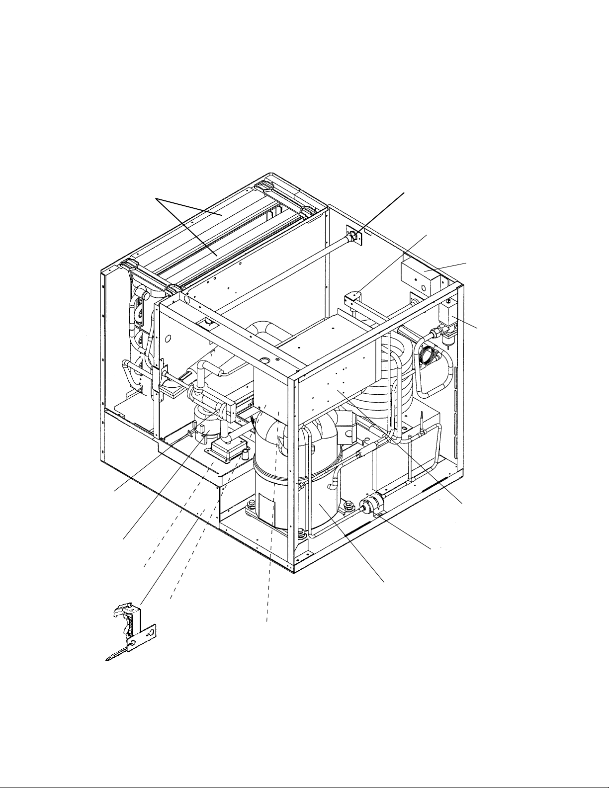
[c] KML-600MAF, KML-600MAH
Spray Tubes
Expansion
Valve
Water Supply
Inlet
Hot Gas Valve
Junction Box
Condenser
Condenser
Fan Motor
Water Pump
Float Switch
Mechanical
Bin Control
(except models
with Thermostat)
Control Box
Drier
Compressor
Control Switch
Bin Control
Thermostat
(except models with
Mechanical Bin Control)
29
Page 30
[d] KML-600MWF, KML-600MWH
Spray Tubes
Water Supply
Inlet
Hot Gas Valve
Junction Box
Water
Regulator
Expansion
Valve
Water Pump
Float Switch
Mechanical
Bin Control
(except models
with Thermostat)
Control Box
Drier
Compressor
Control Switch
Bin Control
Thermostat
(except models with
Mechanical Bin Control)
30
Page 31

[e] KML-600MRF, KML-600MRH
Spray Tubes
Water Supply
Inlet
Hot Gas Valve
Junction Box
Receiver
Tank
Expansion
Valve
Water Pump
Float Switch
Mechanical
Bin Control
(except models
with Thermostat)
Control Box
Drier
Compressor
Control Switch
Hot Gas Valve
Bin Control
Thermostat
(except models with
Mechanical Bin Control)
31
Page 32

2. CONTROLLER BOARD
[a] SOLID-STATE CONTROL
1) A HOSHIZAKI exclusive solid-state control is employed in Modular Crescent Cubers.
2) A Printed Circuit Board (hereafter called “Controller Board”) includes a stable and high
quality control system.
3) All models are pretested and factory-adjusted.
[b] CONTROLLER BOARD
CAUTION
1. Fragile, handle very carefully.
2. A controller board contains integrated circuits, which are susceptible to
failure due to static discharge. It is especially important to touch the metal
part of the unit when handling or replacing the board.
3. Do not touch the electronic devices on the board or the back of the board to
prevent damage to the board.
4. Do not change wiring and connections. Do not misconnect K3, K4 and K5,
because the same connector is used for the Thermistor (white), Float
Switch (black), and Mechanical Bin Control (red).
(For machines with thermostat, there is no connection on K4.)
5. Always replace the whole board assembly when it goes bad.
6. Do not short out power supply to test for voltage.
PART NUMBER TYPE
2A1410-01 HOS-001A (Control Products)
Features of Control Products “E” Controller Board
1) Maximum Water Supply Period - 6 minutes
Water Solenoid Valve opening, in the Defrost (Harvest) Cycle, is limited by the defrost
timer. The Water Valve cannot remain open longer than the
maximum period. The Water Valve can close in less than six minutes if the defrost cycle
is completed.
32
Page 33

2) Defrost Timer
The defrost cycle starts when the Float Switch opens and completes the freeze cycle.
But the Defrost Timer does not start counting until the Thermistor senses 48°F at the
Evaporator outlet. The period from the end of the freeze cycle up to the point of the
Thermistor's sensing varies depending on the ambient and water temperatures.
3) High Temperature Safety - 127 ± 7°F
The temperature of the suction line in the refrigerant circuit is limited by the High
Temperature Safety.
During the defrost cycle the Evaporator temperature rises. The Thermistor senses
48°F and starts the Defrost Timer. After the Defrost Timer counts down to zero,
the normal freeze cycle begins. If the Evaporator temperature continues to rise,
the Thermistor will sense the rise in temperature and at 127 ± 7°F the Thermistor
operates the High Temperature Safety.
This High Temperature Safety shuts down the circuit and the icemaker automatically
stops. To reset the safety, turn the power off and back on again.
This High Temperature Safety protects the unit from excessive temperature. The Control
Board will Beep every 3 seconds. The white Reset Button on the Control Board must be
pressed with power on to reset the Safety.
4) Low Water Safety
If the Pump Motor is operated without water, the mechanical seal can fail. To prevent this
type of failure, the Controller Board checks the position of the Float Switch at the end of
the initial one minute water fill cycle and at the end of each defrost cycle.
If the Float Switch is in the up position (electrical circuit closed), the Controller Board
changes to the ice making cycle. If the Float Switch is in the down position (electrical
circuit open), the Controller Board changes to a one minute water fill cycle before starting
the ice making cycle. This method allows for a Low Water Safety shut down to protect
the Water Pump from mechanical seal failure.
For water-cooled model, if the water is shut off, the unit is protected by the High Pressure
Switch.
5) High Voltage Cutout
The maximum allowable supply voltage of this icemaker is limited by the High Voltage Cutout.
If miswiring (especially on single phase 3 wire models) causes excessive voltage on the
Controller Board, the High Voltage Cutout shuts down the circuit in 3 seconds and the icemaker
automatically stops. When the proper supply voltage is resumed, the icemaker automatically
starts running again. The Control Board will signal this problem using 7 Beeps every 3 seconds.
6) LED Lights and Audible Alarm Safeties
The red LED indicates proper control voltage and will remain on unless a control voltage
problem occurs. At startup a 5 second delay occurs while the board conducts an internal
timer check. A short beep occurs when the power switch is turned ON or OFF.
33
Page 34

The green LED’s 1-4 represent the corresponding relays and energize and sequence 5
seconds from initial start-up as follows:
Sequence Step LED’s on Length: Min. Max. Avg.
1 Minute Fill Cycle LED4 60 sec.
Harvest Cycle LED1, 4, & 2 2 min. 20 min. 3-5 min.
Freeze Cycle LED1 5 min. 60 min. 30-35 min.
Reverse Pump Out LED1, 3, & 2 10 sec. 20 sec. Factory set.
{LED 1 – Comp; LED 2 - HGV/CFM; LED 3 – PM; LED 4 - WV}
The built in safeties shut down the unit and have alarms as follows:
1 beep every 3 sec. = High Evaporator Temperature >127 ° F.
Check for defrost problem (stuck HGV or relay), hot water entering unit, stuck
headmaster, or shorted thermistor.
2 beeps every 3 sec. = Defrost Back Up Timer. Defrost >20 minutes.
Orange LED marked 20 MIN energizes.
Check for open thermistor, HGV not opening, TXV leaking by, low charge, or inefficient
compressor.
3 beeps every 3 sec. = Freeze Back Up Timer. Freeze > 60 minutes.
Yellow LED marked 60 MIN energizes.
Check for F/S stuck closed (up), WV leaking by, HGV leaking by, TXV not feeding
properly, low charge, or inefficient compressor.
4 beeps every 3 sec. = Short Circuit between the K4 connection on
Machines
with
mechanical
bin control
ONLY
the control board and the bin control relay. Check connections and
replace wire harness if necessary.
5 beeps every 3 sec. = Open Circuit between the K4 connection
on the control board and the bin control relay. Check connections and
replace wire harness if necessary.
To manually reset the above safeties, depress white alarm reset button with the power
supply ON.
6 beeps every 3 sec. = Low Voltage. Voltage is 92 Vac or less.
7 beeps every 3 sec. = High Voltage. Control voltage > 147 Vac ±5%.
The red LED will de-energize if voltage protection operates.
The voltage safety automatically resets when voltage is corrected.
The Output Test switch “S3” provides a relay sequence test. With power OFF, place S3
ON and switch power to ICE. The correct lighting sequence should be none, 2, 3, 4, 1, &
4, normal sequence every 5 seconds. S3 should remain in the “OFF” position for normal
operation.
34
Page 35

The application switch located between relay X3 & X4 must be set to match the original
board application. Place this switch in the ALP position if there is no white wire supplied
to the K1 connector. If there is a white wire, place the switch in the C position. If this
switch is placed in the wrong position, either the compressor contactor will remain energized with the control switch OFF, or the unit will not start.
The dip switches should be adjusted per the adjustment chart published in the Tech
Specs book. Number 8 must remain in the OFF position.
(Control Products HOS-001A Board)
35
Page 36

[c] SEQUENCE
1st Cycle
1. Unit energized and Control Switch to “ICE”
position. Water supply cycle starts.
2. After 1 minute,
Defrost cycle starts.
3. Thermistor reads 48° F.
Defrost Timer starts counting.
5. After the first 5 minutes in freeze cycle.
Ready to complete freeze cycle when Float
Switch circuit opens.
IMPORTANT
Board never accepts freeze completion signal
within the first 5 minutes in freeze cycle.
IMPORTANT
Water Valve
opening is limited
to 6 minutes.
&
4. Defrost Timer stops counting.
Defrost cycle is completed and freeze cycle
starts.
IMPORTANT
1. Board never accepts defrost completion
signal within the first 2 minutes in defrost
cycle.
2. Defrost cycle time is limited to 20 minutes
even if Defrost Timer does not stop counting.
36
Page 37

2nd Cycle and after with pump drain
IMPORTANT
Freeze cycle time is limited to 60 minutes even
if Float Switch does not open.
1. Float Switch opens and signals to complete
freeze cycle.
Drain timer starts counting.
2. Drain timer stops counting.
Pump drain is completed
3. Thermistor reads 48° F.
Defrost Timer starts
counting.
IMPORTANT
Water Valve
opening is limited to 6
minutes.
5. After the first 5 minutes in freeze cycle.
Ready to complete freeze cycle when Float
Switch circuit opens.
IMPORTANT
Board never accepts freeze completion signal
within the first 5 minutes in freeze cycle.
4. Defrost Timer stops counting.
Defrost cycle is completed and freeze cycle
starts.
IMPORTANT
1. Board never accepts defrost completion
signal within the first 2 minutes in defrost
cycle.
2. Defrost cycle time is limited to 20 minutes
even if Defrost Timer does not stop counting.
37
Page 38

2nd Cycle and after with no pump drain
IMPORTANT
Freeze cycle time is limited to 60 minutes even
if Float Switch does not open.
1. Float Switch opens and signals to complete
freeze cycle.
&
2. Thermistor reads 48° F.
Defrost Timer starts counting.
IMPORTANT
Water Valve
opening is limited to 6
minutes.
4. After the first 5 minutes in freeze cycle.
Ready to complete freeze cycle when Float
Switch circuit opens.
IMPORTANT
Board never accepts freeze completion signal
within the first 5 minutes in freeze cycle.
3. Defrost Timer stops counting.
Defrost cycle is completed and freeze cycle
starts.
IMPORTANT
1. Board never accepts defrost completion
signal within the first 2 minutes in defrost
cycle.
2. Defrost cycle time is limited to 20 minutes
even if Defrost Timer does not stop counting.
38
Page 39

[d] CONTROLS AND ADJUSTMENTS
The Dip Switch is factory-adjusted to the following positions:
FOR MODELS WITH THERMOSTAT:
DIP SWITCH NO. 1 2 3 4 5 6 7 8 9 10
KML-250 MAH OFF OFF OFF ON ON ON OFF OFF ON OFF
KML-250 MWH OFF OFF OFF ON ON ON OFF OFF OFF ON
350M_F, 350M_H OFF OFF OFF ON ON ON OFF OFF OFF ON
KML-450M_F, M_H
KML-600MAF, MAH
KML-600MWF, MWH
KML-600MRF, MRH ON OFF OFF OFF ON ON OFF OFF OFF ON
OFF OFF OFF OFF ON ON OFF OFF OFF ON
FOR MODELS WITH MECHANICAL BIN CONTROL:
DIP SWITCH NO. 1 2 3 4 5 6 7 8 9 10
KML-250 MAH OFF OFF OFF ON ON ON ON OFF ON OFF
KML-250 MWH OFF OFF OFF ON ON ON ON OFF OFF ON
350M_F, 350M_H OFF OFF OFF ON ON ON ON OFF OFF ON
KML-450M_F, M_H
KML-600MAF, MAH
KML-600MWF, MWH
KML-600MRF, MRH ON OFF OFF OFF ON ON ON OFF OFF ON
OFF OFF OFF OFF ON ON ON OFF OFF ON
Switch Nos. 1 and 2:
Used for adjustment of the Defrost Timer.
The Defrost Timer starts counting when the Thermistor reads a certain temperature
at the Evaporator outlet.
Switch Nos. 3 and 4:
Used for adjustment of the Drain Timer.
When a freeze cycle is completed, the Pump Motor stops, and the icemaker
resumes operation in 2 seconds. Then the Pump Motor drains the Water Tank
for the time determined by the Drain Timer. The Drain Timer also determines the
time to restrain completion of a defrost cycle, i.e. the minimum defrost time.
Switch Nos. 5 and 6:
Used for adjustment of the Drain Counter.
The Pump Motor drains the Water Tank at the frequency determined by the Drain
Counter.
39
Page 40

Switch No. 7:
Used only on models with mechanical bin control. Dip Switch should be set “ON”.
(Models with bin thermostat, Switch No. 7 should be set in the “OFF” position.)
Switch No. 8:
Used only for checking the Controller Board. Usually set in OFF position.
Switch Nos. 9 and 10:
Used for adjustment of Freeze Timer.
The Freeze Timer determines maximum
freeze cycle time. Upon termination of
Freeze Timer, machine initiates the
harvest cycle. After 2 consecutive timer
terminations, machine will shut down,
possibly indicating a problem.
1) Defrost Control
A thermistor (Semiconductor) is used for a defrost control sensor. The resistance
varies depending on the Suction Line temperatures. The Thermistor detects the
temperature of the Evaporator outlet to start the Defrost Timer. No adjustment is
required. If necessary, check for resistance between Thermistor leads, and visually
check the Thermistor mounting, located on the Suction Line next to the Evaporator
outlet.
Temperature (°F) Resistance (kΩ)
0 14.401
10 10.613
32 6.000
50 3.871
70 2.474
90 1.633
Check a thermistor for resistance by using the following procedures.
(i) Disconnect the connector K3 on the board.
(ii) Remove the Thermistor. See “V. 11. REMOVAL AND REPLACEMENT OF
THERMISTOR.”
(iii) Immerse the Thermistor sensor portion in a glass containing ice and water for 2 or 3
minutes.
(iv) Check for a resistance between Thermistor leads.
Normal reading is within 3.5 to 7 kΩ. Replace the Thermistor if it exceeds the normal
reading.
40
Page 41

2) Defrost Timer
No adjustment is required under normal use, as the Defrost Timer is adjusted to the suit-
able position. However, if necessary when all the ice formed on the Evaporator does not
fall into the bin in the harvest cycle, adjust the Defrost Timer to longer setting by adjusting
the Dip Switch (No. 1 & 2) on the Controller Board.
SETTING TIME
Dip Switch Dip Switch
No. 1 No. 2
OFF OFF 60 seconds
ON OFF 90 seconds
OFF ON 120 seconds
ON ON 180 seconds
3) Drain Timer
The Drain Timer is factory-adjusted, and no adjustment is required.
SETTING TIME
Dip Switch Dip Switch
No. 3 No. 4 T1 T2
OFF OFF 10 seconds 150 seconds
ON OFF 10 seconds 180 seconds
OFF ON 10 seconds 120 seconds
ON ON 20 seconds 180 seconds
T1: Time to drain the Water Tank
T2: Time to restrain defrost completion
4) Drain Counter
CAUTION
Do not adjust the Drain Counter, or the Evaporator may freeze up.
The Drain Counter is factory-adjusted to drain the Water Tank every 10 cycles, and no
adjustment is required. However, where water quality is bad and the icemaker needs a
pump drain more often, the Drain Counter can be adjusted as shown in the table below:
41
Page 42

SETTING FREQUENCY
Dip Switch Dip Switch
No. 5 No. 6
OFF OFF every cycle
ON OFF every 2 cycles
OFF ON every 5 cycles
ON ON every 10 cycles
5) Freeze Timer
CAUTION
Adjust to proper specification, or the unit may not operate correctly.
Two new dip switches numbered 9 and 10 have been added to the improved “E”
board to better prevent possible freeze ups. These settings come factory set to the
default setting of 60 min. (OFF, OFF). Check the adjustment chart published in the
Tech Specs for proper settings. If the old board does not have these two dip switches,
(only 8 instead of 10), leave setting as OFF, OFF.
6) Bin Control
MODELS WITH THERMOSTAT
When the ambient temperature is below 45°F, the Bin Control Thermostat
operates to stop the icemaker even if the Ice Storage Bin is empty. When
the Thermostat is set in the prohibited range, the icemaker operates
continuously even if the Ice Storage Bin is filled with ice. Setting in the
prohibited range might cause severe damage to the icemaker resulting in
failure.
SETTING TIME
Dip Switch Dip Switch
No. 9 No. 10
OFF OFF 60 min.
ON OFF 70 min.
OFF ON 50 min.
ON ON 60 min.
CAUTION
No adjustment is required under normal use, as the Bin Control is factory-adjusted.
Adjust it, if necessary, so that the icemaker stops automatically within 10 seconds after
ice contacts the Bin Control Thermostat Bulb.
42
Page 43

MODELS WITH MECHANICAL BIN CONTROL
CAUTION
Dip Switch No. 7 must be set to the ON position. If No. 7 is set to the OFF
position, the machine will run continuously, causing a freeze-up condition.
No adjustment is required. The Bin Control is factory-adjusted.
[e] CHECKING THE CONTROLLER BOARD
1) Visually check the sequence with the icemaker operating.
2) Visually check the Controller Board by using the following procedures.
(i) Adjust the Defrost Timer to minimum position.
Disconnect the Thermistor from the Controller Board.
Connect a 1.5 kΩ - 3.5 kΩ resistor to the Connector K3 (pins #1 and #2), and energize
the unit.
After the 1 minute ± 5 second water supply cycle and the 2 minute ± 10 second defrost
cycle, the unit should start the freeze cycle.
(ii) After the above step (i), disconnect the Float Switch leads from the Controller Board
within the first 5 minutes of the freeze cycle.
The unit should go into the defrost cycle after the first 5 minutes ± 20 seconds of the
freeze cycle.
(iii) Reconnect the Float Switch Connector to the Controller Board. After the first 5
minutes of the freeze cycle, disconnect the Float Switch leads from the Controller
Board.
At this point, the unit should start the defrost cycle.
(iv) After Step (iii), de-energize the unit and confirm that the Defrost Timer is in the
minimum position. Disconnect the resistor from the Controller Board, and energize the unit.
After the 1 minute water supply cycle, the defrost cycle starts.
Reconnect a 1.5 kΩ - 3.5 kΩ resistor to the Connector K3 (pins #1 and #2) after the
first 2 minutes of the defrost cycle.
The unit should start the freeze cycle after 1 minute ± 5 seconds from the resistor
connection.
43
Page 44

3) Check the Controller Board by using test program of the Controller Board.
The Output Test Switch “S3” provides a relay sequence test. With power OFF, place S3
on and switch power to ICE. The correct lighting sequence should be none, 2, 3, 4, 1, and
4, normal sequence every 5 seconds. S3 should remain in the “OFF” position for normal
operation.
3. SWITCHES
Two control switches are used to control operation in the KML Series Modular Crescent
Cubers. These switches are referred to as the “Control Switch” and the “Service Switch.”
[a] CONTROL SWITCH
The Control Switch is located on the lower left section of the control box when facing
the front of the machine. This switch is used to place the machine into one of three
modes: “Power Off” (Center position), “Ice Making” (Right position), and “Service” (Left
position).
[b] SERVICE SWITCH
When the Control Switch is pushed to the left, the machine is placed in “Service” mode.
In this position the Control Switch supplies power to the Service Switch. The Service
Switch can be used to perform three functions: Drain the tank (left position), Circulate
water (center position), Wash the ice making compartment (right position). When the
Service Switch is activated power is supplied to the pump in all three positions.
1) Drain
The KML series utilizes a pump-out drain system. When the Service Switch is active
and placed in the left position, power is supplied to the pump and the Drain solenoid
valve.
2) Wash
The KML series utilizes a solenoid operated cleaning valve. When the Service Switch
is active and placed in the right position, power is supplied to the pump and the Bypass
solenoid valve. This cleans both the inside and outside of the evaporator plate
assembly.
3) Circulate
When the Service switch is active and placed in the center position, power is supplied
to the pump only. This operation can be used to circulate cleaner for extended periods
of time over the outside surface of the Evaporator.
44
Page 45

4. MECHANICAL BIN CONTROL
(THESE INSTRUCTIONS NOT APPLICABLE TO MODELS WITH THERMOSTAT)
[a] PROXIMITY SWITCH
1) This machine uses a lever-actuated proximity switch (hereafter called “mechanical bin
control”) to control the ice level in the storage bin.
[b] EXPLANATION OF OPERATION
1) The startup and shutdown of the ice machine is controlled via the controller board.
Dip Switch number seven must be in the ON position for the controller board to receive input from the bin control.
The controller board receives a resistance value input via the red K4 connector
(i)
from the bin control. A resistor wire harness is connected from the bin control to
the controller board.
(ii) When the bin control is activated in the bin full position (pushed to the right), a
15.8 KΩ signal will be sent to the control board to shut down the unit.
(iii) When the bin control is in the normal position (bin is not full), a 7.9 KΩ reading is
sent to the control board to continue operation.
2) During operation, the controller board will only shut down the machine if a 15.8 KΩ
signal is received from the bin control during the first 5 minutes of the freeze cycle.
(i) If ice pushes the lever to the right after the first five minutes of the freeze cycle,
the controller board will allow the machine to complete the freeze cycle and the
following harvest cycle before shutting down the machine. This will prevent
incomplete batches of ice from forming on the evaporator.
(ii) If the sensor detects ice within ½ inch of the face and energizes the bin control
relay during the harvest cycle, the controller board will allow the machine to
complete the harvest cycle before shutting down the machine. This will ensure
that all ice has been removed from the evaporator before shutting the machine
down.
45
Page 46

[c] TROUBLESHOOTING (MECHANICAL BIN CONTROL ONLY)
1) Machine will not start
(i) Move dip switch No. 7 to the “OFF” position. If the machine starts up within a few
seconds, the bin control is the likely problem. If the machine does not start up,
refer to Section “IV. Service Diagnosis” to verify that non-bin control related issues
are resolved.
(ii)
Check to make sure shipping tape has been removed and the wires are connected
properly.
(iii) Check to make sure no obstruction prevents the lever from moving to the bin empty
position.
2) Machine will not shut off
(i)
Refer to Section “IV. Service Diagnosis” to verify that non-bin control related issues
are resolved.
(ii) Dip switch No. 7 should be in the on position. If the switch is in the off position, the
controller board will not receive input from the bin control.
(iii) Move the lever to the far right.
a. If the machine does not shut off, check the resistance values of the resistor
wire harness. You should read approximately 15.8 KΩ between the black
terminal and the red terminal that connect to the K4 connector on the controller board, when the lever is in the bin full position (far right). If this reads
approximately 7.9 KΩ, the resistors are miswired. Switch the black and
white wires in the terminal housing or order a replacement wire harness.
b. Check the stainless steel bracket that the bin control is mounted to.
c. If the preceding items do not resolve the problem, replace the Bin Control
Assembly.
46
Page 47

III. TECHNICAL INFORMATION
1. WATER CIRCUIT AND REFRIGERANT CIRCUIT
[a] KML-250MAH
KML-350MAF, KML-350MAH
KML-450MAF, KML-450MAH
KML-600MAF, KML-600MAH
47
Page 48

[b] KML-250MWH
KML-350MWF, KML-350MWH
KML-450MWF, KML-450MWH
KML-600MWF, KML-600MWH
48
Page 49

[c] KML-600MRF, KML-600MRH
49
Page 50

2. WIRING DIAGRAMS
[a] KML-250MAH (Beginning Serial #L00001E, ending Serial #M10460F;
KML-250MWH (Beginning Serial #L10001K, ending Serial #M10090D)
KML-250MWH Pressure Switch
Cut-out 384 PSIG
Cut-in 284.5 ± 21.3 PSIG
Cut-out 412.5 PSIG
Cut-in 327 ± 21.3 PSIG
Note: KML-250MAH Pressure Switch
50
Page 51

51
[b]
KML-250MAH (Beginning Serial #M20461G);
KML-250MWH (Beginning Serial #M20091G)
Note: KML-250MAH Pressure Switch
Cut-out 412.5 PSIG
Cut-in 327 ± 21.3 PSIG
KML-250MWH Pressure Switch
Cut-out 384 PSIG
Cut-in 284.5 ± 21.3 PSIG
Page 52

52
[c] KML-350MAF and KML-350MWF
Note: KML-350MAF Pressure Switch
Cut-out 412.5 PSIG
Cut-in 327 ± 21.3 PSIG
KML-350MWF Pressure Switch
Cut-out 384 PSIG
Cut-in 284.5 ± 21.3 PSIG
Page 53

53
[d]
KML-350MWH (Beginning Serial #L00001J, ending Serial #M30080F)
KML-350MAH (Beginning Serial #L00001L, ending Serial #M10290F);
Note: KML-350MAH Pressure Switch
Cut-out 412.5 PSIG
Cut-in 327 ± 21.3 PSIG
KML-350MWH Pressure Switch
Cut-out 384 PSIG
Cut-in 284.5 ± 21.3 PSIG
Page 54

54
[e]
KML-350MAH (Beginning Serial #M20291G);
KML-350MWH (Beginning Serial #M40081G)
Note: KML-350MAH Pressure Switch
Cut-out 412.5 PSIG
Cut-in 327 ± 21.3 PSIG
KML-350MWH Pressure Switch
Cut-out 384 PSIG
Cut-in 284.5 ± 21.3 PSIG
Page 55

55
[f] KML-450MAF and KML-450MWF
Note: KML-450MAF Pressure Switch
Cut-out 412.5 PSIG
Cut-in 327 ± 21.3 PSIG
KML-450MWF Pressure Switch
Cut-out 384 PSIG
Cut-in 284.5 ± 21.3 PSIG
Page 56

56
[g]
KML-450MAH (Beginning Serial #L00101C, ending Serial #L00950G);
KML-450MWH (Beginning Serial #L00001D, ending Serial #L00200G)
Note: KML-450MAH Pressure Switch
Cut-out 412.5 PSIG
Cut-in 327 ± 21.3 PSIG
KML-450MWH Pressure Switch
Cut-out 384 PSIG
Cut-in 284.5 ± 21.3 PSIG
Page 57

57
[h]
KML-450MWH (Beginning Serial #L10201H, ending Serial #M20710F)
KML-450MAH (Beginning Serial #L20951H, ending Serial #M12770F);
Note: KML-450MAH Pressure Switch
Cut-out 412.5 PSIG
Cut-in 327 ± 21.3 PSIG
KML-450MWH Pressure Switch
Cut-out 384 PSIG
Cut-in 284.5 ± 21.3 PSIG
Page 58

58
[i]
KML-450MWH (Beginning Serial #M30711G)
KML-450MAH (Beginning Serial #M22771G);
Note: KML-450MAH Pressure Switch
Cut-out 412.5 PSIG
Cut-in 327 ± 21.3 PSIG
KML-450MWH Pressure Switch
Cut-out 384 PSIG
Cut-in 284.5 ± 21.3 PSIG
Page 59

59
[j] KML-600MAF, KML-600MWF, and KML-600MRF
Note: KML-600MWF Pressure Switch
Cut-out 384 PSIG
Cut-in 284.5 ± 21.3 PSIG
KML-600MAF, MRF Pressure Switch
Cut-out 412.5 PSIG
Cut-in 327 ± 21.3 PSIG
+21.3
- 0
+21.3
- 0
Page 60

[k] KML-600MAH (Beginning Serial #L00001F, ending Serial #L00070F);
KML-600MWH (Beginning Serial #L00001D, ending Serial #L00080E);
KML-600MRH (Beginning Serial #L00001F, ending Serial #L00050F)
60
Cut-out 384 PSIG
Cut-in 284.5 ± 21.3 PSIG
KML-600MAH, MRH Pressure Switch
Cut-out 412.5 PSIG
Cut-in 327 ± 21.3 PSIG
Note: KML-600MWH Pressure Switch
Page 61

[l] KML-600MAH (Beginning Serial #L10071H, ending Serial #M10460G);
KML-600MWH (Beginning Serial #L10081K, ending Serial #M10140E);
KML-600MRH (Beginning Serial #L10051H, ending Serial #M10350E)
61
Cut-out 384 PSIG
Cut-in 284.5 ± 21.3 PSIG
KML-600MAH, MRH Pressure Switch
Cut-out 412.5 PSIG
Cut-in 327 ± 21.3 PSIG
Note: KML-600MWH Pressure Switch
Page 62

62
[m]
KML-600MRH (Beginning Serial #M20331E)
KML-600MAH (Beginning Serial #M2_ _ _ _ _);
KML-600MWH (Beginning Serial #M20141F);
Note: KML-600MWH Pressure Switch
Cut-out 384 PSIG
Cut-in 284.5 ± 21.3 PSIG
KML-600MAH, MRH Pressure Switch
Cut-out 412.5 PSIG
Cut-in 327 ± 21.3 PSIG
Page 63

3. TIMING CHART
When Control Sw. is turned OFF, Pressure Sw. is OFF, Thermistor Temp. exceeds t1,
or Bin Control is in full position (during first 5 minutes of freeze cycle for
mechanical bin control only *3).
If Float Sw. is OFF
Hi Temp Mid Temp Lo Temp Too Lo Temp Normal Too Hi Temp Lo Water
Time Up (60 sec)
Control
Sw. in
ICE
Bin
Thermostat ON
Pressure
Sw. ON
Overheat
Protect
Reset
From Defrost Cycle
To Defrost Cycle
Max. Min.
60 min 5 min
*1
*
*1
*
*NOTE:
*1 The icemaker does not complete a defrost cycle in the first 2 or 3 minutes. See “II. 2. [d]
CONTROLS AND ADJUSTMENTS.”
*3 (Mechanical bin control only) The bin control will only shut off the ice machine during the first five
minutes of the freeze cyle.
Min. Max. Max.
2 min 6 min 6 min
Max.
20 min
63
Page 64

To Stand-by Cycle (When Control Sw. is turned OFF, Pressure Sw. is OFF, Thermistor Temp. exceeds
t1, or Bin Control is in full position)
To Freeze Cycle
From Freeze Cycle
Control
Sw. in
1
*
WASH
2
*
2
*
Min. Max. Max.
3 min 6 min 6 min
Max.
20 min
*1 The Pump Motor waits for 2 seconds before starting a drain cycle. See “II. 2. [d] CONTROLS AND
ADJUSTMENTS.”
*2 The icemaker does not complete a defrost cycle in the first 2 or 3 minutes. See “II. 2. [d] CONTROLS
AND ADJUSTMENTS.”
*3 (Mechanical bin control only) The bin control will only shut off the ice machine during the first five
minutes of the freeze cyle.
64
Page 65

4. PERFORMANCE DATA
[a] KML-250MAH
65
Page 66

[b] KML-250MWH
66
Page 67

[c] KML-350MAF
67
Page 68

[d] KML-350MWF
68
Page 69

[e] KML-350MAH
69
Page 70

[f] KML-350MWH (Serial #L00001J through M20060C)
70
Page 71

[g] KML-350MWH (Beginning Serial #M30061E)
71
Page 72

[h] KML-450MAF
72
Page 73

[i] KML-450MWF
73
Page 74

[j] KML-450MAH
74
Page 75

[k] KML-450MWH (Serial #L00001D through M10530B)
75
Page 76

[l] KML-450MWH (Beginning Serial #M20531D)
76
Page 77

[m] KML-600MAF
77
Page 78

[n] KML-600MWF
78
Page 79

[o] KML-600MRF
79
Page 80

[p] KML-600MAH
80
Page 81

[q] KML-600MWH (Serial #L00001D through Serial #M10115C)
81
Page 82

[r] KML-600MWH (Beginning Serial #M10121E)
82
Page 83

[s] KML-600MRH
83
Page 84

IV. SERVICE DIAGNOSIS
1. NO ICE PRODUCTION
PROBLEM POSSIBLE CAUSE REMEDY
[1] The icemaker a) Power Supply 1. “OFF” position. 1. Move to “ON” position
will not start 2. Loose connections. 2. Tighten
3. Bad contacts. 3. Check for continuity and
replace.
4. Voltage too high. 4. Check and get
recommended voltage.
b) Fuse (Inside Fused 1. Blown out. 1. Check for short circuit
Disconnect, if any) and replace
c) Control Switch 1. “OFF” position. 1. Move to “ICE” position.
2. Bad contacts. 2. Check for continuity and
replace.
d) Bin Control 1. Tripped with bin filled 1. Remove ice.
Thermostat with ice.
2. Ambient temperature 2. Increase ambient
For mechanical
bin control,
see “II. 4. [c]”
e) High Pressure 1. Bad contacts. 1. Check for continuity and
Control replace.
f) Transformer 1. Thermal fuse blown out 1. Replace.
g) Wiring to 1. Loose connections or 1. Check for continuity and
Controller Board open. replace.
h) Thermistor 1. Leads short-circuit or 1. See “II.2.[d] CONTROLS
i) Hot Gas Solenoid 1. Continues to open in 1. Check for power off in
Valve freeze cycle and High freeze cycle and replace.
j) Water Supply Line 1. Water supply off and 1. Check and get
k) Water Solenoid 1. Mesh filter or orifice gets 1. Clean.
too cool. temperature.
3. Set too warm. 3. See “II.2.[d]
CONTROLS AND
ADJUSTMENTS, 5) Bin
Control.”
4. Bulb out of position. 4. Place in position.
5. Bad contacts or leaks 5. Check for continuity and
bulb. replace.
or coil winding opened.
open and High AND ADJUSTMENTS, 1)
Temperature Safety Defrost Control.”
operates.
Temperature Safety
operates.
water supply cycle does recommended
not finish. pressure.
2. Condenser water 2. Check and get
pressure too low or off recommended
and Pressure Control pressure.
opens and closes fre quently to finally operate
High Temperature Safety.
clogged and water supply
cycle does not finish.
2. Coil winding opened. 2. Replace.
3. Wiring to Water Valve. 3. Check for loose
connection or open, and
replace.
84
Page 85

PROBLEM POSSIBLE CAUSE REMEDY
l) Controller Board 1. Defective 1. See “II.2[e] CHECKING
CONTROLLER BOARD.”
[2] Water a) Float switch 1. Connector disconnected. 1. Place in position.
continues to 2. Leads opened or defective 2. Check and replace.
be supplied, switch.
and the ice- 3. Float does not move freely. 3. Clean or replace.
maker will not b) Controller Board 1. Defective. 1. Replace.
start.
[3] Compressor a) Control Switch 1. “SERVICE” position. 1. Move to “ICE” position.
2. Bad contacts. 2. Check and replace.
b) High Pressure 1. Dirty Air Filter or 1. Clean.
Controller Condenser.
2. Ambient or condenser 2. Reduce ambient temp.
water temp. too warm.
3. Refrigerant overcharged. 3. Recharge.
4. Condenser water pressure 4. Check and get
too low or off. [Water- recommended pressure.
cooled model only].
5. Fan not operating. [Except 5. See chart 1 - [6].
water-cooled model].
6. Refrigerant line or 6. Clean and replace Drier.
components plugged.
c) Water Regulator 1. Set too high. 1. Adjust lower.
d) Overload Protector 1. Bad contacts. 1. Check for continuity and
replace.
2. Voltage too low. 2. Increase voltage.
3. Refrigerant overcharged or 3. Recharge.
undercharged.
4. Line Valve continues to 4. Check Line Valve's
close in freeze cycle and operation in freeze cycle
Overload Protector and replace.
operates.
e) Starter 1. Bad contacts. 1. Check and replace.
2. Coil winding opened. 2. Replace.
f) Start Capacitor or 1. Defective. 1. Replace.
Run Capacitor
g) Magnetic Contactor 1. Bad contacts. 1. Check for continuity and
replace.
2. Coil winding opened. 2. Replace.
h) Compressor 1. Wiring to Compressor. 1. Check for loose
connection or open, and
replace.
2. Defective. 2. Replace.
3. Protector tripped. 3. Reduce temperature.
i) Controller board 1. Defective. 1. See “II.2. [e] CHECKING
CONTROLLER BOARD.”
85
Page 86

PROBLEM POSSIBLE CAUSE REMEDY
[4] Water a) Water Solenoid 1. Diaphragm does not close. 1. Check for water leaks
continues to Valve with icemaker off.
be supplied in b) Controller Board 1. Defective. 1. See “II.2.[e] CHECKING
freeze cycle. CONTROLLER BOARD.”
[5] No water a) Water Supply Line 1. Water pressure too low and 1. Check and get
comes from water level in Water Tank recommended pressure.
Spray Tubes. too low.
Water Pump b) Water Solenoid 1. Dirty mesh filter or orifice 1. Clean.
will not start, or Valve and water level in Water
freeze cycle Tank too low.
time is too c) Water System 1. Water leaks. 1. Check connections for
short. water leaks, and replace.
2. Clogged. 2. Clean.
d) Pump Motor 1. Motor winding opened. 1. Replace.
2. Bearing worn out. 2. Replace.
3. Wiring to Pump Motor. 3. Check for loose
connection or open, and
replace.
4. Defective or bound impeller. 5. CLEAN
e) Controller Board 1. Defective. 1. See “II.2. [e] CHECKING
CONTROLLER BOARD.”
[6] Fan Motor will a) Fan Motor 1. Motor winding opened. 1. Replace.
not start, or is 2. Bearing worn out. 2. Replace.
not operating. 3. Wiring to Fan Motor. 3. Check for loose
connection or open, and
replace.
4. Defective Capacitor. 4. Replace
5. Fan blade bound. 5. Check and replace.
b) Controller Board 1. Defective. 1. See “II.2. [e] CHECKING
CONTROLLER BOARD.”
[7] All components a) Refrigerant 1. Undercharged. 1. Check for leaks and
run but no ice recharge.
is produced. 2. Air or moisture trapped. 2. Replace Drier, and
recharge.
b) Compressor 1. Defective valve. 1. Replace.
c) Hot Gas Solenoid 1. Continues to open in freeze 1. Check and replace.
Valve cycle.
d) Line Valve 1. Continues to close in 1. Check and replace
freeze cycle.
e) Water Supply Line 1. Condenser water pressure 1. Check and get
[Water-cooled model too low or off and Pressure recommended pressure.
only] Control opens and closes
frequently.
86
Page 87

2. EVAPORA TOR IS FROZEN UP
PROBLEM POSSIBLE CAUSE REMEDY
[1] Freeze cycle a) Float Switch 1. Leads short-circuit or 1. Check and replace.
time is too defective switch.
long. 2. Float does not move freely. 2. Clean or replace.
b) Water Solenoid 1. Diaphragm does not close. 1. Check for water leaks
Valve with icemaker off.
c) Controller Board 1. Defective. 1. See “II.2[e] CHECKING
CONTROLLER BOARD.”
[2] All ice formed a) Evaporator 1. Scaled up. 1. Clean.
on Evaporator b) Water Supply Line 1. Water pressure too low. 1. Check and get
does not fall recommended pressure.
into bin in c) Water Solenoid 1. Dirty mesh filter or orifice. 1. Clean.
harvest cycle. Valve 2. Diaphragm does not close. 2. Check for water leaks
with icemaker off.
d) Ambient and/or 1. Too cool. 1. Increase temperature.
water temperature
e) Thermistor 1. Out of position or loose 1. See “V. 11. REMOVAL
attachment. AND REPLACEMENT OF
THERMISTOR.”
f) Controller Board 1. Defrost Timer is set too 1. Adjust longer, referring
short. to “II. 2. [d] CONTROLS
AND ADJUSTMENT, 2)
Defrost Timer.”
2. Defective. 2. See “II. 2.[e] CHECKING
CONTROLLER BOARD.”
[3] Others a) Spray Tube 1. Clogged. 1. Clean.
2. Out of position. 2. Place in position.
b) Water System 1. Dirty. 1. Clean.
c) Refrigerant 1. Undercharged. 1. Check for leaks and
recharge.
d) Expansion Valve 1. Bulb out of position or 1. Place in position.
loose attachment.
2. Defective. 2. Replace.
e) Hot Gas Solenoid 1. Coil winding opened. 1. Replace.
Valve 2. Plunger does not move. 2. Replace.
3. Wiring to Hot Gas Valve. 3. Check for loose
connection or open, and
replace.
3. LOW ICE PRODUCTION
PROBLEM POSSIBLE CAUSE REMEDY
[1] Freeze cycle a) See chart 1 - [3], and check dirty Air Filter or Condenser, ambient or water
time is long. temperature, water pressure, Water Regulator or refrigerant charge.
b) See chart 2 - [1], and check Float Switch, Water Solenoid Valve or Controller
Board.
[2] Harvest cycle a) See chart 2 - [2], and check Controller Board, Thermistor, Evaporator, ambient
time is long and/or water temperature, water supply line, Water Solenoid Valve.
87
Page 88

4. ABNORMAL ICE
PROBLEM POSSIBLE CAUSE REMEDY
[1] Small Cube a) Ice Cube Guide 1. Out of position. 1. Place in position.
Circulated water falls into
bin.
b) See chart 1 - [5], and check water supply line, Water Solenoid Valve, water system,
Pump Motor or Controller Board.
c) Drain Valve 1. Dirty. 1. Clean.
[2] Cloudy or a) See chart 2 - [1] and - [3], and check Float Switch, Water Solenoid Valve,
irregular cube Controller Board, Spray Tubes, water system, refrigerant charge or Expansion
Valve.
b) Spray Guide 1. Dirty. 1. Clean.
c) Water Quality 1. High hardness or contains 1. Install a water filter or
impurities. softener.
5. OTHERS
PROBLEM POSSIBLE CAUSE REMEDY
[1] Icemaker will a) Bin Control 1. Set too cold. 1. Adjust warmer.
not stop when Thermostat 2. Defective. 2. Replace.
bin is filled
with ice.
For mechanical
bin control,
see “II. 4. [c]”
[2] Abnormal a) Pump Motor 1. Bearings worn out. 1. Replace.
noise b) Fan Motor 1. Bearings worn out. 1. Replace.
2. Fan blade deformed. 2. Replace fan blade.
3. Fan blade does not move 3. Replace.
freely.
c) Compressor 1. Bearings worn out, or 1. Replace.
cylinder valve broken.
2. Mounting pad out of 2. Reinstall
position.
d) Refrigerant Lines 1. Rub or touch lines or other 1. Replace.
surfaces.
[3] Ice in storage a) Bin Drain 1. Plugged. 1. Clean.
bin often
melts.
88
Page 89

V. REMOVAL AND REPLACEMENT OF COMPONENTS
IMPORTANT
Ensure all components, fasteners and thumbscrews are securely in place
after the equipment is serviced.
IMPORTANT
1. The Polyol Ester (POE) oils used in R-404A units can absorb moisture
quickly. Therefore it is important to prevent moisture from entering the
system when replacing or servicing parts.
2. Always install a new filter drier every time the sealed refrigeration system is
opened.
3. Do not leave the system open for longer than 5 minutes when replacing or
servicing parts.
1. SERVICE FOR REFRIGERANT LINES
[a] REFRIGERANT RECOVERY
The icemaker unit is provided with two Refrigerant Access Valves–one on the low-side and
one on the high-side line. Using proper refrigerant practices recover the refrigerant from
the Access Valves and store it in an approved container. Do not discharge the refrigerant
into the atmosphere.
[b] EVACUATION AND RECHARGE [R-404A]
1) Attach Charging Hoses, a Service Manifold and a Vacuum Pump to the system. Be
sure to connect charging hoses to both High and Low -side Access Valves.
IMPORTANT
The vacuum level and Vacuum Pump may be the same as those for current
refrigerants. However, the rubber hose and gauge manifold to be used for
evacuation and refrigerant charge should be exclusively for POE oils.
2) Turn on the Vacuum Pump. Never allow the oil in the Vacuum Pump to flow backward.
3) Allow the Vacuum Pump to pull down to a 29.9" Hg vacuum. Evacuating period
depends on pump capacity.
4) Close the Low-side Valve and High-side Valve on the Service Manifold.
89
Page 90

5) Disconnect the Vacuum Pump, and attach a Refrigerant Service Cylinder to
the High-side line. Remember to loosen the connection, and purge the air
from the Hose. See the Nameplate for the required refrigerant charge.
Hoshizaki recommends only virgin refrigerant or reclaimed refrigerant which
meets ARI Standard No. 700-88 be used.
6) A liquid charge is recommended for charging an R-404A system. Invert the service
cylinder. Open the High-side, Service Manifold Valve.
7) Allow the system to charge with liquid until the pressures balance.
8) If necessary, add any remaining charge to the system through the Low-side. Use a
throttling valve or liquid dispensing device to add the remaining liquid charge through
the Low-side access port with the unit running.
9) Close the two Refrigerant Access Valves, and disconnect the Hoses and Service
Manifold.
10) Cap the Access Valves to prevent a possible leak.
2. BRAZING
1. Refrigerant R-404A itself is not flammable at atmospheric pressure and
temperatures up to 176° F.
2. Refrigerant R-404A itself is not explosive or poisonous. However, when
exposed to high temperatures (open flames) R-404A can be decomposed
to form hydrofluoric acid and carbonyl fluoride both of which are hazardous.
3. Always recover the refrigerant and store it in an approved container. Do not
discharge the refrigerant into the atmosphere.
4. Do not use silver alloy or copper alloy containing Arsenic.
5. Do not use R-404A as a mixture with pressurized air for leak testing.
Refrigerant leaks can be detected by charging the unit with a little refrigerant,
raising the pressure with nitrogen and using an electronic leak detector.
DANGER
Note: All brazing-connections inside the Evaporator Case are clear-paint coated.
Sandpaper the brazing connections before debrazing the components. Use a
good abrasive cloth to remove coating.
90
Page 91

3. REMOVAL AND REPLACEMENT OF COMPRESSOR
IMPORTANT
Always install a new Drier every time the sealed refrigeration system is opened.
Do not replace the Drier until after all other repair or replacement has been
made.
Note: When replacing a Compressor with a defective winding, be sure to install the new Start
Capacitor and Start Relay supplied with the replacement Compressor. Due to the
ability of the POE oil in the compressor to absorb moisture quickly, the Compressor
must not be opened more than 15 minutes for replacement or service. Do not mix
lubricants of different compressors even if both are charged with R-404A, except when
they use the same lubricant.
1) Turn off the power supply.
2) Remove the panels.
3) Recover the refrigerant and store it in an approved container.
4) Remove the Terminal Cover on the Compressor, and disconnect the Compressor Wiring.
5) Remove the Discharge and Suction Pipes using brazing equipment.
6) Remove the Hold-down Bolts, Washers and Rubber Grommets.
7) Slide and remove the Compressor. Unpack the new Compressor package. Install the
new Compressor.
8) Attach the Rubber Grommets of the prior Compressor.
9) Sandpaper the Suction, Discharge and Process Pipes.
10) Place the Compressor in position, and secure it using the Bolts and Washers.
11) Remove plugs from the Suction, Discharge and Process Pipes.
12) Braze the Process, Suction and Discharge lines (Do not change this order), while purging
with nitrogen gas flowing at the pressure 3 - 4 PSIG.
13) Install the new Filter Drier.
14) Check for leaks using nitrogen gas (140 PSIG) and soap bubbles.
91
Page 92

15) Evacuate the system, and charge it with refrigerant. For air-cooled and water-cooled
models, see the Nameplate for the required refrigerant charge. For remote air-cooled
models, see the Charge Label in the machine compartment.
16) Connect the Terminals, and replace the Terminal Cover in its correct position.
17) Replace the panels in their correct positions.
18) Turn on the power supply.
4. REMOVAL AND REPLACEMENT OF DRIER
IMPORTANT
Always install a new Drier every time the sealed refrigeration system is opened.
Do not replace the Drier until after all other repair or replacement has been
made.
1) Turn off the power supply.
2) Remove the panels.
3) Recover the refrigerant and store it in an approved container.
4) Remove the Drier.
5) Install the new Drier, with the arrow on the Drier, in the direction of the refrigerant flow.
Use nitrogen gas at the pressure of 3 - 4 PSIG when brazing the tubings.
6) Check for leaks using nitrogen gas (140 PSIG) and soap bubbles.
7) Evacuate the system, and charge it with refrigerant. For air-cooled and water-cooled
models, see the Nameplate for the required refrigerant charge. For remote air-cooled
models, see the Charge Label in the machine compartment.
8) Replace the panels in their correct positions.
9) Turn on the power supply.
92
Page 93

5. REMOVAL AND REPLACEMENT OF EXPANSION VALVE
IMPORTANT
Sometimes moisture in the refrigerant circuit exceeds the Drier capacity and
freezes up at the Expansion Valve. Always install a new Drier every time the
sealed refrigeration system is opened. Do not replace the Drier until after all
other repair or replacement has been made.
1) Turn off the power supply.
2) Remove the panels.
3) Recover the refrigerant and store it in an approved container.
4) Remove the insulation and the Expansion Valve Bulb on the suction line.
5) Remove the Expansion Valve Cover, and disconnect the Expansion Valve using
brazing equipment.
6) Braze the new Expansion Valve, with nitrogen gas flowing at the pressure of 3 - 4
PSIG.
W ARNING
Always protect the valve body by using a damp cloth to prevent the valve
from overheating. Do not braze with the valve body exceeding 250°F.
7) Install the new Drier.
8) Check for leaks using nitrogen gas (140 PSIG) and soap bubbles.
9) Evacuate the system, and charge it with refrigerant. For air-cooled and water-cooled
models, see the Nameplate for the required refrigerant charge. For remote air-cooled
models, see the Charge Label in the machine compartment.
10) Attach the Bulb to the suction line in position. Be sure to secure it with clamps and to
insulate it.
11) Place the new set of Expansion Valve Covers in position.
12) Replace the panels in their correct positions.
13) Turn on the power supply.
93
Page 94

6. REMOVAL AND REPLACEMENT OF HOT GAS VALVE AND LINE
VALVE
CAUTION
Always use a copper tube of the same diameter and length when replacing
the hot gas lines; otherwise the performance may be reduced.
IMPORTANT
Always install a new Drier every time the sealed refrigeration system is
opened. Do not replace the Drier until after all other repair or replacement
has been made.
1) Turn off the power supply.
2) Remove the panels.
3) Recover the refrigerant and store it in an approved container.
4) Remove the screw and the Solenoid.
5) Disconnect the Hot Gas Valve or Line Valve using brazing equipment.
6) Install the new valve.
W ARNING
Always protect the valve body by using a damp cloth to prevent the valve
from overheating. Do not braze with the valve body exceeding 250°F.
7) Install the new Drier.
8) Check for leaks using nitrogen gas (140 PSIG) and soap bubbles.
9) Evacuate the system, and charge it with refrigerant. For air-cooled and water cooled models, see the Nameplate for the required refrigerant charge. For remote
air-cooled models, see the Charge Label in the machine compartment.
94
Page 95

10) Cut the leads of the Solenoid allowing enough lead length to reconnect using
closed end connectors.
11) Connect the new Solenoid leads.
12) Attach the Solenoid to the valve body, and secure it with a screw.
13) Replace the panels in their correct positions.
14) Turn on the power supply.
95
Page 96

7. REMOVAL AND REPLACEMENT OF EVAPORATOR
IMPORTANT
Always install a new Drier every time the sealed refrigeration system is
opened. Do not replace the Drier until after all other repairs or replacement
have been made.
1) Turn off the power supply.
2) Remove the panels and the Top Insulation over the Evaporator.
3) Recover the refrigerant and store it in an approved container.
4) Remove the Spray Tubes and the Insulations at the “U” shaped notch where the
refrigeration tubings go through the molded chassis.
5) Remove the Insulation Tube, and disconnect the Evaporator Inlet Tubing at the Tee
next to the Expansion Valve.
6) Lift up the Evaporator, and disconnect the Evaporator Outlet Tubing.
7) Install the new Evaporator.
8) Install the new Drier.
9) Check for leaks using nitrogen gas (140 PSIG) and soap bubbles.
10) Evacuate the system, and charge it with refrigerant. For air-cooled and water cooled models, see the Nameplate for the required refrigerant charge. For remote
air-cooled models, see the Charge Label in the machine compartment.
11) Replace the removed parts in the reverse order of which they were removed.
12) Replace the Top Insulation and the panels in their correct positions.
13) Turn on the power supply.
96
Page 97

8. REMOVAL AND REPLACEMENT OF WATER REGULA TING VALVE WATER-COOLED MODEL ONLY
IMPORTANT
Always install a new Drier every time the sealed refrigeration system is
opened. Do not replace the Drier until after all other repair or replacement
has been made.
1) Turn off the power supply.
2) Close the Water Supply Line Shut-off Valve.
3) Remove the panels.
4) Recover the refrigerant and store it in an approved container.
5) Disconnect the Capillary Tube at the Condenser outlet using brazing equipment.
6) Disconnect the Flare-connections of the valve.
7) Remove the screws and the valve from the Bracket.
8) Install the new valve, and braze the Capillary Tube.
9) Install the new Drier.
10) Check for leaks using nitrogen gas (140 PSIG) and soap bubbles.
11) Evacuate the system, and charge it with refrigerant. See the Nameplate for the
required refrigerant charge.
12) Connect the Flare-connections.
13) Open the Water Supply Line Shut-off Valve.
14) Check for water leaks.
15) Replace the panels in their correct positions.
16) Turn on the power supply.
97
Page 98

9. ADJUSTMENT OF WATER REGULA TING VAL VE - W ATER-COOLED
MODEL ONLY
The Water Regulating Valve (also called “WATER REGULATOR”) is factory-adjusted.
No adjustment is required under normal use. Adjust the Water Regulator, if necessary,
using the following procedures.
1) Attach a pressure gauge to the high-side line of the system. Or prepare a
thermometer to check for the condenser drain temperature.
2) Rotate the adjustment screw by using a flat blade screwdriver, so that the pressure
gauge shows 270 PSIG or the thermometer reads 104-115 °F, 5 minutes after a
freeze cycle or icemaking process starts. When the pressure exceeds 270 PSIG,
or the condenser drain temperature exceeds 115 ° F, rotate the adjustment screw
counterclockwise. See Fig. 1.
3) Check that the pressure or the condenser drain temperature holds a stable setting.
Fig. 1
98
Page 99

10. REMOVAL AND REPLACEMENT OF CONDENSING PRESSURE
REGULATOR (C.P.R.) - REMOTE AIR-COOLED MODEL ONLY
IMPORTANT
Always install a new Drier every time the sealed refrigeration system is
opened. Do not replace the Drier until after all other repair or replacement
has been made.
1) Turn off the power supply.
2) Remove the panels from the remote condenser unit.
3) Recover the refrigerant and store it in an approved container.
4) Before heating, break off the stub on the dome to release the dome charge.
5) Disconnect the C.P.R. using brazing equipment.
6) Install the new C.P.R. Use nitrogen gas at the pressure of 3 - 4 PSIG when brazing
the C.P.R.
WARNING
Always protect the C.P.R. body by using a damp cloth to prevent the
C.P.R. from overheating. Do not braze with the C.P.R. body exceeding
250° F.
7) Install the new Drier in the icemaker.
8) Check for leaks using nitrogen gas (140 PSIG) and soap bubbles.
9) Evacuate the system and charge it with refrigerant. See the Charge Label in the
machine compartment in the icemaker.
10) Replace the panels in their correct positions.
11) Turn on the power supply.
99
Page 100

11. REMOVAL AND REPLACEMENT OF THERMISTOR
CAUTION
1. Fragile, handle very carefully.
2. Always use a recommended sealant (High Thermal Conductive Type),
Model KE4560RTV manufactured by SHINETSU SILICONE, Part Code
60Y000-11, or Part Code 4A0683-01 or equivalent.
3. Always use a recommended foam insulation (Non-absorbent Type) or
equivalent.
4. Do not shorten or cut the Thermistor leads when installing it.
1) Turn off the power supply.
Thermistor Lead Cable Tie
2) Remove the panels.
3) Remove the Control Box Cover.
4) Disconnect the Thermistor leads from
the K3 Connector on the Controller Board.
5) Remove the Plastic Cable Ties, Foam
Insulation, Thermistor Holder and
Thermistor. See Fig. 2.
Foam Insulation Thermistor Holder
Fig. 2
6) Scrape away the old sealant on the
Thermistor Holder and the Suction Pipe.
7) Wipe off moisture or condensation on the Suction Pipe.
8) Smoothly apply recommended sealant (KE4560RTV, Part Code 60Y000-11 or
4A0683-01) to the Thermistor Holder concave.
9) Attach the new Thermistor to the Suction Pipe very carefully to prevent damage to
the leads. And secure it using the Thermistor Holder and recommended foam
insulation.
100
 Loading...