

Page 1
Hoshizaki America, Inc.
Hoshizaki
Low-Profile Modular Crescent Cuber
Model
KML-700MWH-M
“A Superior Degree
of Reliability”
www.hoshizaki.com
PARTS LIST
™
Number: 71336
Issued: 7-7-2011
Page 2

CONTENTS
Auxiliary Codes ...................................................................................................................... 3
Note About Ordering Parts .................................................................................................... 3
A. Ice Cuber Assembly and Refrigeration Circuit ................................................................... 4
B. Water Circuit ...................................................................................................................... 7
C. Control Box Assembly ....................................................................................................... 9
D. Label Location ................................................................................................................. 10
E. Accessories & Packaging .................................................................................................11
2
Page 3

Auxiliary Codes
KML-700MWH-M U-0 October 2009
A-0 April 2011
A-1 TBD
Auxiliary Code Breakdown
The auxiliary code is the rst two characters in the serial number. The rst character
indicates the year. Years progress or regress in alphabetical order. The series runs from
"A" through "V" and the letters "I" and "O" are skipped. The second character indicates
signicant part changes within a year. Base is "0" and this number advances for each
change. In cases where there is a letter in parentheses, this designates the month. This is
the last character in the serial number. The series runs from "(A)" through "(M)" and the
letter "(I)" is skipped. This designation is only included when identifying a parts change
within an auxiliary code.
Note About Ordering Parts
Most assemblies cannot be ordered as complete units; parts in the assemblies generally
must be ordered separately.
3
Page 4
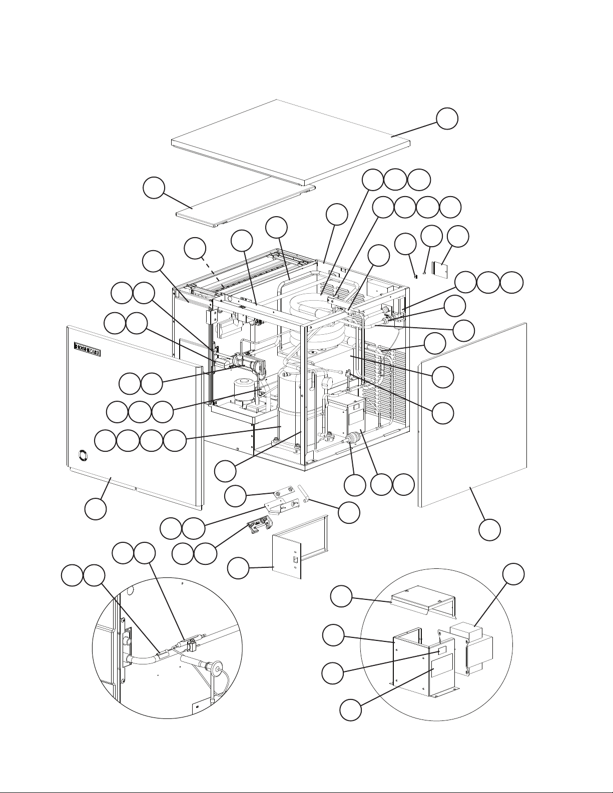
A. Ice Cuber Assembly and Refrigeration Circuit
KML-700MWH-M
U-0 to A-1
13
24
24a
16
24b
17
26
41
11
42
35
26a
14
4443
36
11a
26b 26c
12
18
25
18a
32
21
33
27
23
19
30
45 4746
29
2
8
2a
46a
9
49
22
34
10
31
28
48
28a
15
28b
39 40
37
38
Thermistor and Expansion
Valve Bulb Holder
20
20a
1
3
7
6
4
5
Transformer Box Assembly
4
Page 5

Title: A. Ice Cuber Assembly and Refrigeration Circuit Model: KML-700MWH-M
U-0
Index
No. Description
Ice Cuber Assembly
Order Assembly Parts Individually
1 Control Box Cover 3A5204G01 1
2 Transformer Box Assembly
(includes items 3 through 7)
2a Hex Head Bolt w/Washer 5×10, SS 7B0230510 4
3 Transformer 4A0817-01 1
4 Voltage Tap Switch 4A1477-01 1
5 Voltage Tap Switch Label 439423-01 1
6 Transformer Box 3A1101-02 1
7 Transformer Box Cover 4A4304-01 1
8 Square Washer 433537-02 1
9 Ground Screw 433304-02 1
10 Junction Box Cover 433410-05 1
11 Bin Control Cover 3A0664G01 1
11a Thumbscrew 415949G08 2
12 Capillary Ring 425307-01 1
13 Top Insulation 215730G01 1
14 Front Insulation 2A0664G02 1
15 Right Side Panel 2A2114G01 1
16 Top Panel 3A1862A01 1
17 Front Panel 3A4001A02 1
18 Thermostat Extension Bracket 4A4358-01 1
18a Thumbscrew 415949G10 2
19 Silicone Hose L=310 7730I3812 1
20 Bulb Holder 3A3903-01 1
20a Thumbscrew 415949G11 2
21 NSF Plate 4A4401G01 1
Material or
Model Number Part Number
1A1710A01 1
3A1102A02 1
to
A-1
Required Number
Refrigeration Circuit
Order Assembly Parts Individually
22 Condenser Support 2A4880-01 1
23 Rear Panel 3A3912G02 1
24 Condenser 3A5124-01 1
24a Hex Head Bolt 5×14, SS 7B02-0514 2
24b Washer 4A5063-01 2
25 Evaporator 106492G01 1
26 Compressor 4A4066-01 1
26a Spacer 434921-01 4
26b Grommet 434922-01 4
26c Bolt 8×45 437889-04 4
27 Heat Exchanger 2A4882G01 1
28 Water Regulating Valve 4A0911-07 1
28a Hex Head Bolt 4×8, SS 7B02-0408 2
28b Washer 4A4786-01 2
29 Strainer 441569-02 1
30 Drier 4A2666-01 1
31 Male Connector 4A1087-01 1
1A1683A01 1
5
Page 6

Title: A. Ice Cuber Assembly and Refrigeration Circuit Model: KML-700MWH-M
U-0
Index
No. Description
32 Frame A 2A1153-03 1
33 Frame B 3A0595-02 1
34 High-Pressure Switch 463180-05 1
35 Thermostatic Expansion Valve 4A1482-01 1
36 Thermostatic Expansion Valve
Cover
37 Thermostatic Expansion Valve
Bulb Holder
38 Clamp 443461-02 1
39 Thermistor 429006-03 1
40 Thermistor Holder 427430-01 1
41 Thermistor Insulation A 439368-01 1
42 Thermistor Insulation B 439368-02 1
43 Insulation Holder 3A1084-01 1
44 Insulated Rubber Tube 4A1008G01 1
45 Hot Gas Valve Bracket 442162-02 1
46 Valve Coil (includes item 46a) 4A3277-01 1
46a Bolt 4A3277F01 1
47 Hot Gas Valve Body 4A3978-01 1
48 Condenser Outlet 3A5198G01 1
49 Condenser Inlet 3A5197G01 1
Material or
Model Number Part Number
3A0944-01 1
3A0107-01 1
to
A-1
Required Number
6
Page 7

B. Water Circuit
KML-700MWH-M
U-0 to A-1
7
11
14
15
12
4
6
5
17 18
2
9
10
8
3
26
16
17
34
1
25
30
35
37
31
38
28
29a
29
27
24
23
13
36
21
33
32
20
22
19
7
Page 8

Title: B. Water Circuit Model: KML-700MWH-M
Index
No. Description
Water Circuit
Order Assembly Parts Individually
1 Water Supply Pipe 4A0768G04 1
2 Rubber Gasket 413854-03 1
3 Water Valve Bracket 321443-02 1
4 Spray Tube 1A0260-02 1
5 Spray Guide 208586-01 6
6 Water Supply Tube 2A0079-01 1
7 Plug 4A0176-01 2
8 Water Supply Tee 4A1006-01 1
9 Flange 439267-01 1
10 Insulation E 4A0392-01 1
11 Elbow 4A0393-01 1
12 Connecting Pipe 3A1335-02 1
13 Cube Guide 2A0660-01 1
14 Rubber Ring 4A1004-01 1
15 Bypass Hose 4A1005-01 1
16 Drain Valve Bracket 4A3137-02 1
17 Drain/Wash Valve 4A3722-01 2
18 Wash Valve Cover 4A0996-02 1
19 Float Switch 4A3624-01 1
20 Float Switch Bracket 327757-01 1
21 Float Switch Cover 3A0665-01 1
22 Float Switch Spacer 4A0650-01 1
23 Drain 309246-01 1
24 "O" Ring 7611-P015 1
25 Joint Pipe 439329-01 1
26 Inlet Water Valve 3U0111-04 1
27 Hose B 325867-01 1
28 Pump Motor 4A4259-01 1
29 Pump Motor Bracket 2A4920G01 1
29a Thumbscrew 415949G11 1
30 T2 Screw (pump motor
ground)
31 Tooth Washer (pump motor
ground)
32 Insulation A 4A4783-01 1
33 Insulation B 4A1053-01 1
34 Insulation A1 4A1259-01 1
35 Insulation A2 4A1260-01 1
36 Vinyl Hose L=150 7716-1216 1
37 Vinyl Hose L=55 7716-1519 1
38 Vinyl Hose L=415 7716-1519 1
Hose Clamp 25mm, SS 427443-03 4
Hose Clamp 18mm, SS 427443-05 9
Hose Clamp 20mm, SS 427443-06 1
Material or
Model Number Part Number
2A3782A02 1
4×8, SS 7P32-0408 1
M4, SS 7R22-0400 1
Hose Clamps
Required Number
U-0
to
A-1
8
Page 9

C. Control Box Assembly
KML-700MWH-M
U-0 to A-1
17
2
18
5
10
1
9
6
A-1 and later
U-0, A-0
Title: C. Control Box Assembly Model: KML-700MWH-M
Index
No. Description
Control Box Assembly
Order Assembly Parts Individually
1 Strap 4A2262-06 1 1
2 X10, X11, X12 Relay 406132-07 3 3
3 Control Switch 443119-01 1 1
4 Service Switch 4A0985-01 1 1
5 Control Transformer 3A0172-01 1 1
6 Control Board 2A3792-01 1 1
7 Control Board Support 4A0336-03 4 4
8 Magnetic Contactor 428393-01 1 -
Compressor Relay 4A3140-01 1
9 Run Capacitor 30MFD,
10 Start Capacitor 145-175MFD,
11 Start Relay 4A1107-09 1 1
12 Fuse 4A0893-07 1 1
13 Fuse Holder 4A3449-01 1 1
14 Thermostat 4A2879-01 1 1
15 Control Label 4A1758-01 1 1
16 Pump Motor Capacitor 2.5MFD,
17 Ground Screw 433304-02 1 1
18 Square Washer 433537-02 1 1
8
Material or
Model Number Part Number
2A4965A01 1 2A4965A02 1
3A2005-03 1 1
370VAC
3A0076-01 1 1
250VAC
4A2128-05 1 1
250VAC
7
U-0
A-0 A-1
11
14
12
16
3
4
15
Required Number
13
9
Page 10

D. Label Location
KML-700MWH-M
U-0 to A-1
3
12
6
1
2
10
9
8
4
13
7
15
14
Title: D. Label Location Model: KML-700MWH-M
Index
No. Description
Label Location
Order Assembly Parts Individually
1 Emblem 4A0560-01 1 1
2 Penguin Label 4A0526-01 1 1
3 Maintenance Label 3A5223-01 1 1
4 Wiring Label 3A5248-01 1 -
5 Nameplate 2A3843-04 1 1
6 Vessel Label 4A4006-01 1 1
7 Manual Label 4A4735-01 1 1
8 Tag Warning: Electrical
Connection
9 R404A Label 4A0960-01 1 10 Warning Label K 4A4736-01 1 1
11 Instruction Label 444575-01 1 1
12 Rating Label 2A3844-04 1 1
13 Control Board Label 3A4799-01 1 1
14 Fuse Label 4A2817-01 1 1
15 Alarm Label 4A4737-01 1 1
Material or
Model Number Part Number
3A5208A01 1 1
3A6730-01 1
4A4741-01 1 1
U-0
A-0 A-1
11
5
Required Number
10
Page 11

E. Accessories & Packaging
KML-700MWH-M
U-0 to A-1
Title: E. Accessories & Packaging Model: KML-700MWH-M
Index
No. Description
1 Instruction Manual 91A1HL10A 1
2 Universal Brace 4A0363-02 2
2a Hex Head Bolt 5×12, SS 7B02-0512 2
Packaging 2A2126A02 1
Material or
Model Number Part Number
Required Number
U-0
to
A-1
11
 Loading...