

Hoshizaki America KMD-700MAH Service Manual
Reliability is a
beautiful thing
TM
MODULAR CRESCENT CUBER
KMD-700MAH
KMD-700MWH
KMD-700MRH
SERVICE MANUAL
KMD-900MAH
KMD-900MWH
KMD-900MRH
ITEM #: 73107
™
ISSUED: June 2, 2003
REVISED: July 28, 2006

IMPORTANT
Only qualified service technicians should attempt to service or maintain this
icemaker. No service or maintenance should be undertaken until the technician
has thoroughly read this Service Manual.
HOSHIZAKI provides this manual primarily to assist qualified service technicians in the
service and maintenance of the icemaker.
Should the reader have any questions or concerns which have not been satisfactorily
addressed, please call or write to the HOSHIZAKI Technical Support Department for
assistance.
HOSHIZAKI AMERICA, INC.
618 Highway 74 South
Peachtree City, GA 30269
Attn: HOSHIZAKI Technical Support Department
Phone: 1-800-233-1940 Technical Service
(770) 487-2331
Fax: (770) 487-3360
Web Site: www.hoshizakiamerica.com
NOTE: To expedite assistance, all correspondence/communication MUST include the
following information:
• Model Number
• Serial Number
•
Complete and detailed explanation of the problem
2

Please review this manual. It should be read carefully before the icemaker is serviced or
maintenance operations are performed. Only qualified service technicians should
service and maintain the icemaker. This manual should be made available to the
technician prior to service or maintenance.
CONTENTS
I. Specifications .................................................................................................................... 5
1. KMD-700MAH .............................................................................................................. 5
2. KMD-700MWH ............................................................................................................. 6
3. KMD-700MRH .............................................................................................................. 7
4. KMD-900MAH .............................................................................................................. 8
5. KMD-900MWH ............................................................................................................. 9
6. KMD-900MRH ............................................................................................................ 10
7. Condensing Unit......................................................................................................... 11
URC-12F.................................................................................................................. 11
II. General Information ........................................................................................................ 13
1. Construction ............................................................................................................... 13
[a] KMD-700MAH ..................................................................................................... 13
[b] KMD-700MWH .................................................................................................... 14
[c] KMD-700MRH ..................................................................................................... 15
[d] KMD-900MAH ..................................................................................................... 16
[e] KMD-900MWH .................................................................................................... 17
[f] KMD-900MRH ...................................................................................................... 18
2. Controller Board ......................................................................................................... 19
[a] Solid-State Control .............................................................................................. 19
[b] Controller Board .................................................................................................. 19
[c] Sequence ............................................................................................................ 23
[d] Controls and Adjustments ................................................................................... 26
[e] Checking the Controller Board ............................................................................ 30
3. Mechanical Bin Control .............................................................................................. 31
[a] Proximity Switch .................................................................................................. 31
[b] Explanation of Operation ..................................................................................... 31
[c] Troubleshooting ................................................................................................... 32
III. Technical Information ..................................................................................................... 33
1. Water Circuit and Refrigerant Circuit........................................................................... 33
[a] KMD-700MAH and KMD-900MAH ...................................................................... 33
[b] KMD-700MWH and KMD-900MWH .................................................................... 34
[c] KMD-700MRH and KMD-900MRH ...................................................................... 35
2. Wiring Diagrams ......................................................................................................... 36
[a1] KMD-700MAH and KMD-700MWH (auxiliary code R-0 and earlier) ................. 36
[a2] KMD-700MAH and KMD-700MWH (auxiliary code R-1 and later) .................... 37
[b1] KMD-700MRH (auxiliary code R-0 and earlier) ................................................ 38
[b2] KMD-700MRH (auxiliary code R-1 and later) .................................................... 39
[c1] KMD-900MAH and KMD-900MWH (auxiliary code R-0 and earlier) ................. 40
[c2] KMD-900MAH and KMD-900MWH (auxiliary code R-1 and later) .................... 41
[d1] KMD-900MRH (auxiliary code R-0 and earlier) ................................................. 42
[d2] KMD-900MRH (auxiliary code R-1 and later) .................................................... 43
3

3. Timing Chart ............................................................................................................... 44
4. Performance Data ....................................................................................................... 46
[a] KMD-700MAH ..................................................................................................... 46
[b] KMD-700MWH .................................................................................................... 47
[c] KMD-700MRH ..................................................................................................... 48
[d] KMD-900MAH ..................................................................................................... 49
[e] KMD-900MWH .................................................................................................... 50
[f] KMD-900MRH ...................................................................................................... 51
IV. Service Diagnosis.......................................................................................................... 52
1. No Ice Production ....................................................................................................... 52
2. Evaporator is Frozen Up ............................................................................................. 55
3. Low Ice Production ..................................................................................................... 56
4. Abnormal Ice .............................................................................................................. 56
5. Other ........................................................................................................................... 56
V. Removal and Replacement of Components ................................................................... 57
1. Service for Refrigerant Lines ...................................................................................... 57
[a] Refrigerant Recovery........................................................................................... 57
[b] Evacuation and Recharge [R-404A] .................................................................... 57
2. Brazing ....................................................................................................................... 58
3. Removal and Replacement of Compressor ................................................................ 59
4. Removal and Replacement of Drier ........................................................................... 61
5. Removal and Replacement of Expansion Valve......................................................... 61
6. Removal and Replacement of Hot Gas Valve and Line Valve .................................... 62
7. Removal and Replacement of Evaporator .................................................................. 64
8. Removal and Replacement of Water Regulating Valve (Water-Cooled Model Only) .. 65
9. Adjustment of Water Regulating Valve (Water-Cooled Model Only)............................ 66
10. Removal and Replacement of Condensing Pressure Regulator (C.P.R.) (Remote Air-
Cooled Model Only) ................................................................................................. 67
11. Removal and Replacement of Thermistor ................................................................ 68
12. Removal and Replacement of Fan Motor ................................................................. 69
13. Removal and Replacement of Water Valve ............................................................... 70
14. Removal and Replacement of Pump Motor .............................................................. 70
15. Removal and Replacement of Spray Tubes .............................................................. 71
16. Removal and Replacement of Bin Control ............................................................... 72
VI. Cleaning and Maintenance Instructions ........................................................................ 73
1. Preparing the Icemaker for Long Storage ................................................................... 73
2. Cleaning Instructions .................................................................................................. 76
[a] Cleaning Procedure ............................................................................................ 76
[b] Sanitizing Procedure - Following Cleaning Procedure ....................................... 79
3. Maintenance ............................................................................................................... 80
4
I. Specifications
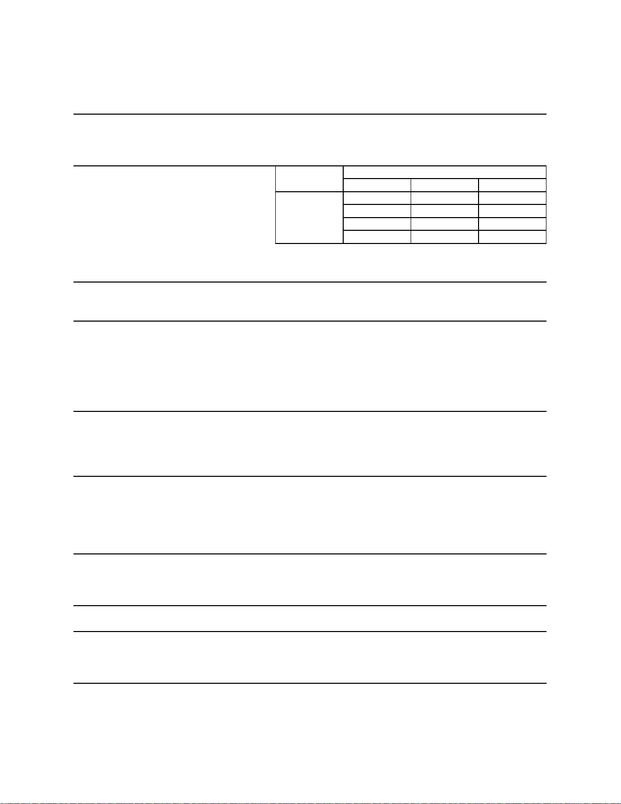
1. KMD-700MAH
AC SUPPLY VOLTAGE 208-230/60/1 (3 wire with neutral for 115V)
AMPERAGE 13.5 A ( 5 Min. Freeze AT 104°F / WT 80°F)
MINIMUM CIRCUIT AMPACITY 14.3 A
MAXIMUM FUSE SIZE 20 A
APPROXIMATE ICE PRODUCTION Ambient WATER TEMP. (°F)
PER 24 HR. Temp.(°F) 50 70 90
lbs./day ( kg/day ) 70 *696 (316) 650 (295) 593 (269)
Reference without *marks 80 661 (300) 589 (267) 536 (243)
90 650 (295) *539 (244) 483 (219)
100 641 (291) 526 (239) 432 (196)
SHAPE OF ICE Crescent Cube
ICE PRODUCTION PER CYCLE 9.6 lbs. (4.4 kg) 624 pcs.
APPROXIMATE STORAGE CAPACITY N/A
ELECTRIC & WATER CONSUMPTION 90/70°F 70/50°F
ELECTRIC W (kWH/100 lbs.) 1590(7.1) 1540(5.3)
WATER gal./24HR (gal./100 lbs.) 202(37.5) 406(58.4)
EXTERIOR DIMENSIONS (WxDxH) 30" x 24.6" x 28" (762 x 625 x 713 mm)
EXTERIOR FINISH Stainless Steel, Galvanized Steel (Rear)
WEIGHT Net 217 lbs. (98 kg), Shipping 249 lbs. (113 kg)
CONNECTIONS - ELECTRIC Permanent - Connection
- WATER SUPPLY Inlet 1/2" FPT
- DRAIN Outlet 3/4" FPT
5/8" OD Tube
CUBE CONTROL SYSTEM Float Switch
HARV ES TING CONTROL SYSTEM Hot Gas and Water, Thermist or and Timer
ICE MAKING WATER CONTROL Timer Controlled. Overflow Pipe
COOLING WATER CONTROL N/A
BIN CONTROL SYSTEM Mechanical Level Switch and Timer
COMPRESSOR Hermetic, Model CS10K6E-PFV-237
CONDENSER Air-Cooled, Fin and Tube Type
EVAPORATOR Vertical type, Stainless Steel and Copper
REFRIGERANT CONTROL Thermostatic Ex pansion Valve
REFRIGERANT CHARGE R-404A, 2 lb. 8.6 oz. (1150g)
DESIGN PRESSURE High 467PSIG, Low 230PSIG
P.C. BOARD CIRCUIT PROTECTION High Voltage Cut-out ( Internal )
COMPRESSOR PROTECTION Auto-reset Overload Protector ( Internal )
REFRIGERANT CIRCUIT PROTECTION Auto-res et High Pres sure Control Switch
LO W W A TE R P ROTE CTION Float S wi t c h
ACCESSORIES -SUPPLIED N/A
-REQUIRED Ice Dispenser or Ice Storage Bin
OPERATING CONDITIONS VOLTAGE RANGE 187 - 253 V
AMBIENT TEMP. 45 -100° F
WATER SUPPLY TEMP. 45 - 90° F
WATER SUPPLY PRESSURE 20 - 145 PSIG
We reserve the right to make changes in specifications and design without prior notice.
5
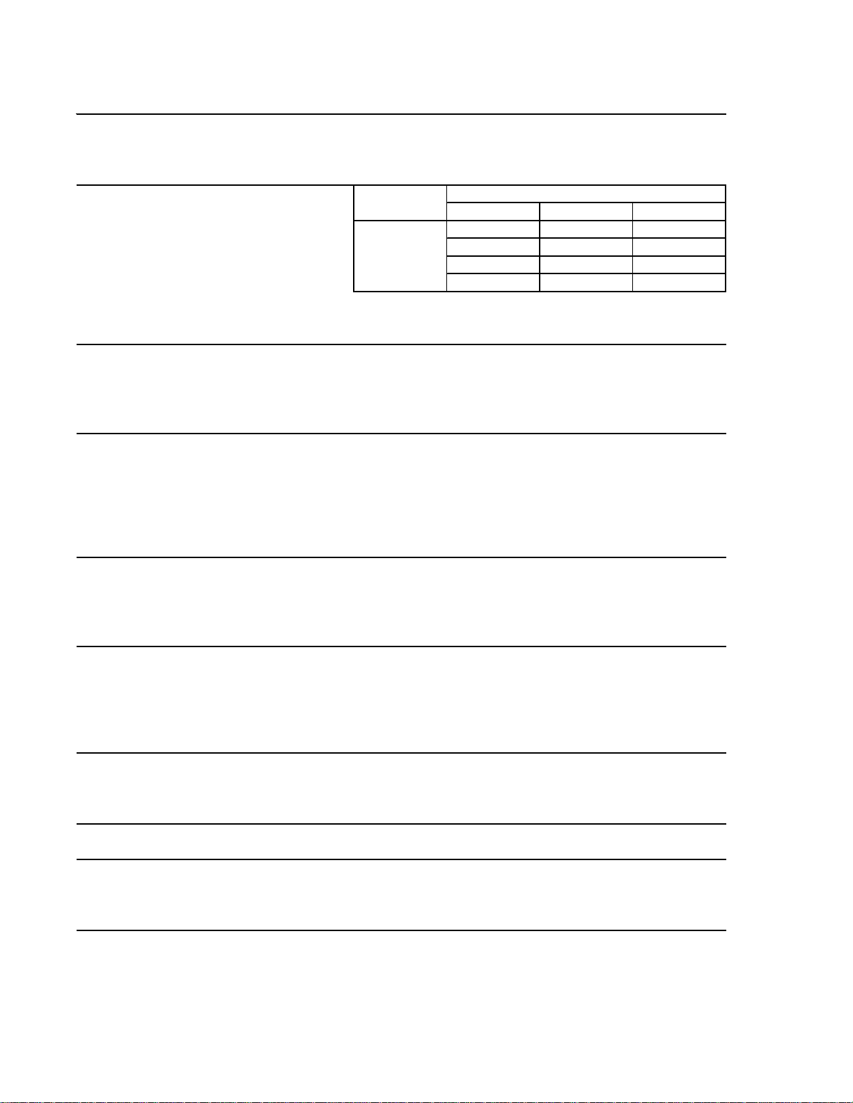
2. KMD-700MWH
AC SUPPLY VOLTAGE 208-230/60/1 (3 wire with neutral for 115V)
AMPERAGE 12 A ( 5 Min. Freeze AT 104°F / W T 80°F)
MINIMUM CIRCUIT AMPACITY 12.9
MAXIMUM FUSE SIZE 20 A
APPROXIMATE ICE PRODUCTION Ambient WATER TEMP. (°F)
PER 24 HR. Temp.(°F) 50 70 90
lbs./day ( kg/day ) 70 *701 (318) 675 (306) 634 (288)
Reference without *marks 80 681 (309) 640 (290) 597 (271)
90 675 (306) *611 (277) 569 (258)
100 665 (302) 601 (273) 530 (240)
SHAPE OF ICE Crescent Cube
ICE PRODUCTION PER CYCLE 9.6 lbs. (4.4 kg) 624 pcs.
APPROXIMATE STORAGE CAPACITY N/A
ELECTRIC & WATER CONSUMPTION 90/70°F 70/50°F
ELECTRIC W (kWH/100 lbs.) 1520(6.0) 1500(5.1)
WATER gal./24HR (gal./100 lbs.) 203(33.3) 272(38.9)
WATER COOLED CONDENSER 607(99) 403(58)
gal./24HR (gal./100 lbs.)
EXTERIOR DIMENSIONS (WxDxH) 30" x 24.6" x 28" (762 x 625 x 713 mm)
EXTERIOR FINISH Stainless Steel, Galvanized Steel (Rear)
WEIGHT Net 217 lbs. (98 kg), Shipping 249 lbs. (113 kg)
CONNECTIONS - ELECTRIC Permanent - Connection
- WATER SUPPLY Inlet 1/2" FPT Condenser Inlet 1/2" FPT
- DRAIN Outlet 3/4" FPT Condenser Outlet 3/8" FPT
5/8" OD Tube
CUBE CONTROL SYSTEM Float Switch
HARV ES TING CONTROL SYSTEM Hot Gas and Water, Thermist or and Timer
ICE MAKING WATER CONTROL Timer Controlled. Overflow Pipe
COOLING WATER CONTROL Pressure Regulator
BIN CONTROL SYSTEM Mechanical Level Switch and Timer
COMPRESSOR Hermetic, Model CS10K6E-PFV-237
CONDENSER Water-cooled, Tube in Tube Type
EVAPORATOR Vertical type, Stainless Steel and Copper
REFRIGERANT CONTROL Thermostatic Ex pansion Valve
REFRIGERANT CHARGE R-404A, 1 lb. 10 Oz. (730g)
DESIGN PRESSURE High 427PSIG, Low 230PSIG
P.C. BOARD CIRCUIT PROTECTION High Voltage Cut-out ( Internal )
COMPRESSOR PROTECTION Auto-reset Overload Protector ( Internal )
REFRIGERANT CIRCUIT PROTECTION Auto-res et High Pres sure Control Switch
LO W W A TE R P ROTE CTION Float S wi t c h
ACCESSORIES -SUPPLIED N/A
-REQUIRED Ice Dispenser or Ice Storage Bin
OPERATING CONDITIONS VOLTAGE RANGE 187 - 253 V
AMBIENT TEMP. 45 -100° F
WATER SUPPLY TEMP. 45 - 90° F
WATER SUPPLY PRESSURE 20 - 145 PSIG
We reserve the right to make changes in specifications and design without prior notice.
6
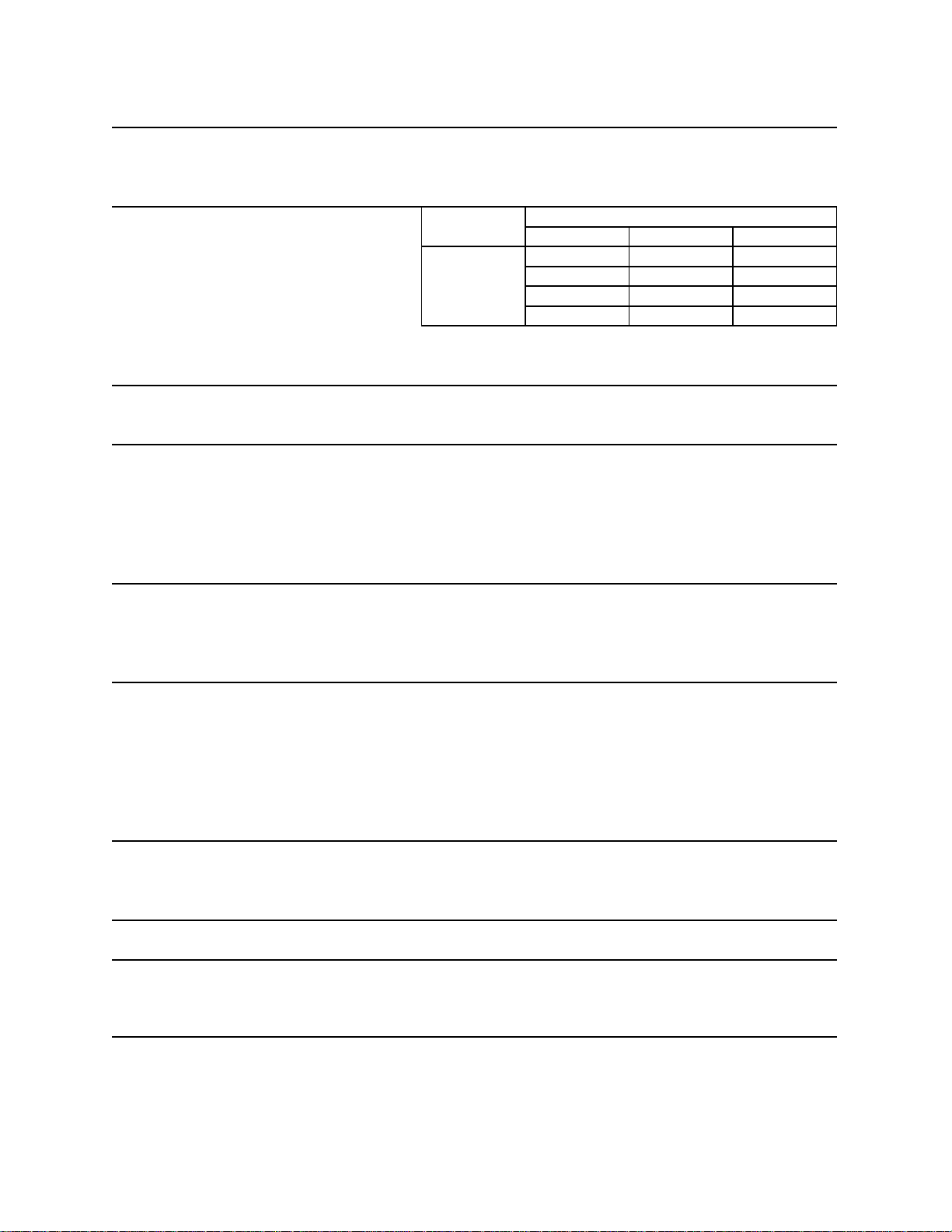
3. KMD-700MRH
AC SUPPLY VOLTAGE 208-230/60/1 (3 wire with neutral for 115V)
AMPERAGE 13 A ( 5 Min. Freeze AT 104°F / W T 80°F)
MINIMUM CIRCUIT AMPACITY 13.15 A
MAXIMUM FUSE SIZE 20 A
APPROXIMATE ICE PRODUCTION Ambient WATER TEMP. (°F)
PER 24 HR. Temp.(°F) 50 70 90
lbs./day ( kg/day ) 70 *730 (331) 715 (324) 655 (297)
Reference without *marks 80 719 (326) 696 (316) 614 (278)
90 715 (324) *679 (308) 605 (275)
100 690 (313) 662 (300) 538 (244)
SHAPE OF ICE Crescent Cube
ICE PRODUCTION PER CYCLE 9.6 lbs. (4.4 kg) 624 pcs.
APPROXIMATE STORAGE CAPACITY N/A
ELECTRIC & WATER CONSUMPTION 90/70°F 70/50°F
ELECTRIC W (kWH/100 lbs.) 1790(6.3) 1750(5.7)
WATER gal./24HR (gal./100 lbs.) 218(32.1) 385(52.7)
EXTERIOR DIMENSIONS (WxDxH) 30" x 24.6" x 28" (762 x 625 x 713 mm)
EXTERIOR FINISH Stainles s Steel, Galvanized Steel (Rear)
WEIGHT Net 203 lbs. (92 kg), Shipping 235 lbs. (107 kg)
CONNECTIONS - ELECTRIC Permanent - Connection
- WATER SUPPLY Inlet 1/2" FPT
- DRAIN Outlet 3/4" FPT
5/8" OD Tube
CUBE CONTROL SYSTEM Float Switch
HARV ES TING CONTROL SYSTEM Hot Gas and Water, Thermist or and Timer
ICE MAKING WATER CONTROL Timer Controlled. Overflow Pipe
COOLING WATER CONTROL N/A
BIN CONTROL SYSTEM Mechanical Level Switch and Timer
COMPRESSOR Hermetic, Model CS10K6E-PFV-279
CONDENSER Air-Cooled Remote, Condenser Unit URC-12 F
EVAPORATOR Vertical type, Stainless Steel and Copper
REFRIGERANT CONTROL Thermostatic Ex pansion Valve
Condensing Pressure Regulator on URC-12F
REFRIGERANT CHARGE R-404A, 10 lb. 0.5 oz. (4550g)
(Icemaker 5 lbs . 9.9 oz. Cond. Unit 4 lb. 6.5 oz .)
DESIGN PRESSURE High 467PSIG, Low 230PSIG
P.C. BOARD CIRCUIT PROTECTION High Voltage Cut-out ( Internal )
COMPRESSOR PROTECTION Auto-reset Overload Protector ( Internal )
REFRIGERANT CIRCUIT PROTECTION Auto-res et High Pres sure Control Switch
LO W W A TE R P ROTE CTION Float S wi t c h
ACCESSORIES -SUPPLIED N/A
-REQUIRED Ice Dispenser or Ice Storage Bin
OPERATING CONDITIONS VOLTAGE RANGE 187 - 253 V
AMBIENT TEMP. 45 -100° F
WATER SUPPLY TEMP. 45 - 90° F
WATER SUPPLY PRESSURE 20 - 145 PSIG
We reserve the right to make changes in specifications and design without prior notice.
7
4. KMD-900MAH
AC SUPPLY VOLTAGE 208-230/60/1 (3 wire with neutral for 115V)
AMPERAGE 15 A ( 5 Min. Freeze AT 104°F / W T 80°F)
MINIMUM CIRCUIT AMPACITY 15.5 A
MAXIMUM FUSE SIZE 25 A
APPROXIMATE ICE PRODUCTION Ambient WATER TEMP. (°F)
PER 24 HR. Temp.(°F) 50 70 90
lbs./day ( kg/day ) 70 *875 (397) 842 (382) 767 (348)
Reference without *marks 80 850 (386) 799 (362) 706 (320)
90 842 (382) *763 (346) 676 (307)
100 817 (370) 743 (337) 596 (270)
SHAPE OF ICE Crescent Cube
ICE PRODUCTION PER CYCLE 9.6 lbs. (4.4 kg) 624 pcs.
APPROXIMATE STORAGE CAPACITY N/A
ELECTRIC & WATER CONSUMPTION 90/70°F 70/50°F
ELECTRIC W (kWH/100 lbs.) 2000(6.3) 1930(5.3)
WATER gal./24HR (gal./100 lbs.) 265(34.7) 507(57.9)
EXTERIOR DIMENSIONS (Wx DxH) 42" x 24.6" x 28" (1067 x 625 x 713 mm)
EXTERIOR FINISH Stainles s Steel, Galvanized Steel (Rear)
WEIGHT Net 240 lbs. (109 kg), Shipping 278 lbs. (126 kg)
CONNECTIONS - ELECTRIC Permanent - Connection
- WATER SUPPLY Inlet 1/2" FPT
- DRAIN Outlet 3/4" FPT
5/8" OD Tube
CUBE CONTROL SYSTEM Float Switch
HARV ES TING CONTROL SYSTEM Hot Gas and Water, Thermist or and Timer
ICE MAKING WATER CONTROL Timer Controlled. Overflow Pipe
COOLING WATER CONTROL N/A
BIN CONTROL SYSTEM Mechanical Level Switch and Timer
COMPRESSOR Hermetic, Model CS14K6E-PFV-237
CONDENSER Air-Cooled, Fin and Tube Type
EVAPORATOR Vertical type, Stainless Steel and Copper
REFRIGERANT CONTROL Thermostatic Ex pansion Valve
REFRIGERANT CHARGE R-404A, 3 lb. 8.3 Oz. (1600g)
DESIGN PRESSURE High 467PSIG, Low 230PSIG
P.C. BOARD CIRCUIT PROTECTION High Voltage Cut-out ( Internal )
COMPRESSOR PROTECTION Auto-reset Overload Protector ( Internal )
REFRIGERANT CIRCUIT PROTECTION Auto-res et High Pres sure Control Switch
LO W W A TE R P ROTE CTION Float S wi t c h
ACCESSORIES -SUPPLIED N/A
-REQUIRED Ice Dispenser or Ice Storage Bin
OPERATING CONDITIONS VOLTAGE RANGE 187 - 253 V
AMBIENT TEMP. 45 -100° F
WATER SUPPLY TEMP. 45 - 90° F
WATER SUPPLY PRESSURE 20 - 145 PSIG
We reserve the right to make changes in specifications and design without prior notice.
8
5. KMD-900MWH
AC SUPPLY VOLTAGE 208-230/60/1 (3 wire with neutral for 115V)
AMPERAGE 14 A ( 5 Min. Freeze AT 104°F / W T 80°F)
MINIMUM CIRCUIT AMPACITY 14.7
MAXIMUM FUSE SIZE 25 A
APPROXIMATE ICE PRODUCTION Ambient WATER TEMP. (°F)
PER 24 HR. Temp.(°F) 50 70 90
lbs./day ( kg/day ) 70 *886 (402) 859 (390) 816 (370)
Reference without *marks 80 865 (392) 823 (373) 777 (352)
90 859 (390) *793 (360) 747 (339)
100 848 (385) 782 (355) 705 (320)
SHAPE OF ICE Crescent Cube
ICE PRODUCTION PER CYCLE 9.6 lbs. (4.4 kg) 624 pcs.
APPROXIMATE STORAGE CAPACITY N/A
ELECTRIC & WATER CONSUMPTION 90/70°F 70/50°F
ELECTRIC W (kWH/100 lbs.) 1950(5.9) 1950(5.3)
WATER gal./24HR (gal./100 lbs.) 301(37.9) 452(51.1)
WATER COOLED CONDENSER 831(105) 526(59)
gal./24HR (gal./100 lbs.)
EXTERIOR DIMENSIONS (WxDxH) 30" x 24.6" x 28" (762 x 625 x 713 mm)
EXTERIOR FINISH Stainles s Steel, Galvanized Steel (Rear)
WEIGHT Net 219 lbs. (99 kg), Shipping 251 lbs. (114 kg)
CONNECTIONS - ELECTRIC Permanent - Connection
- WATER SUPPLY Inlet 1/2" FPT Condenser Inlet 1/2" FPT
- DRAIN Outlet 3/4" FPT Condenser Outlet 3/8" FPT
5/8" OD Tube
CUBE CONTROL SYSTEM Float Switch
HARV ES TING CONTROL SYSTEM Hot Gas and Water, Thermist or and Timer
ICE MAKING WATER CONTROL Timer Controlled. Overflow Pipe
COOLING WATER CONTROL Pressure Regulator
BIN CONTROL SYSTEM Mechanical Level Switch and Timer
COMPRESSOR Hermetic, Model CS14K6E-PFV-237
CONDENSER Water-cooled, Tube in Tube Type
EVAPORATOR Vertical type, Stainless Steel and Copper
REFRIGERANT CONTROL Thermostatic Ex pansion Valve
REFRIGERANT CHARGE R-404A, 2 lb. 0 Oz. (900g)
DESIGN PRESSURE High 427PSIG, Low 230PSIG
P.C. BOARD CIRCUIT PROTECTION High Voltage Cut-out ( Internal )
COMPRESSOR PROTECTION Auto-reset Overload Protector ( Internal )
REFRIGERANT CIRCUIT PROTECTION Auto-res et High Pres sure Control Switch
LO W W A TE R P ROTE CTION Float S wi t c h
ACCESSORIES -SUPPLIED N/A
-REQUIRED Ice Dispenser or Ice Storage Bin
OPERATING CONDITIONS VOLTAGE RANGE 187 - 253 V
AMBIENT TEMP. 45 -100° F
WATER SUPPLY TEMP. 45 - 90° F
WATER SUPPLY PRESSURE 20 - 145 PSIG
We reserve the right to make changes in specifications and design without prior notice.
9
6. KMD-900MRH
AC SUPPLY VOLTAGE 208-230/60/1 (3 wire with neutral for 115V)
AMPERAGE 14 A ( 5 Min. Freeze AT 104°F / W T 80°F)
MINIMUM CIRCUIT AMPACITY 14.65 A
MAXIMUM FUSE SIZE 25 A
APPROXIMATE ICE PRODUCTION Ambient WATER TEMP. (°F)
PER 24 HR. Temp.(°F) 50 70 90
lbs./day ( kg/day ) 70 *906 (411) 878 (398) 814 (369)
Reference without *marks 80 885 (401) 842 (382) 763 (346)
90 878 (398) *812 (368) 737 (335)
100 857 (389) 795 (360) 669 (303)
SHAPE OF ICE Crescent Cube
ICE PRODUCTION PER CYCLE 9.6 lbs. (4.4 kg) 624 pcs.
APPROXIMATE STORAGE CAPACITY N/A
ELECTRIC & WATER CONSUMPTION 90/70°F 70/50°F
ELECTRIC W (kWH/100 lbs.) 2220(6.6) 2075(5.9)
WATER gal./24HR (gal./100 lbs.) 266(33.4) 465(53.1)
EXTERIOR DIMENSIONS (WxDxH) 30" x 24.6" x 28" (762 x 625 x 713 mm)
EXTERIOR FINISH Stainles s Steel, Galvanized Steel (Rear)
WEIGHT Net 226 lbs. (103 kg), Shipping 258 lbs. (117 kg)
CONNECTIONS - ELECTRIC Permanent - Connection
- WATER SUPPLY Inlet 1/2" FPT
- DRAIN Outlet 3/4" FPT
5/8" OD Tube
CUBE CONTROL SYSTEM Float Switch
HARV ES TING CONTROL SYSTEM Hot Gas and Water, Thermist or and Timer
ICE MAKING WATER CONTROL Timer Controlled. Overflow Pipe
COOLING WATER CONTROL N/A
BIN CONTROL SYSTEM Mechanical Level Switch and Timer
COMPRESSOR Hermetic, Model CS14K6E-PFV-279
CONDENSER Air-Cooled Remote, Condenser Unit URC-12 F
EVAPORATOR Vertical type, Stainless Steel and Copper
REFRIGERANT CONTROL Thermostatic Ex pansion Valve
Condensing Pressure Regulator on URC-12F
REFRIGERANT CHARGE R-404A, 9 lb. 6 Oz. (4250g)
(Icemaker 4 lbs. 15 oz. Cond. Unit 4 lb. 7 oz.)
DESIGN PRESSURE High 467PSIG, Low 230PSIG
P.C. BOARD CIRCUIT PROTECTION High Voltage Cut-out ( Internal )
COMPRESSOR PROTECTION Auto-reset Overload Protector ( Internal )
REFRIGERANT CIRCUIT PROTECTION Auto-res et High Pres sure Control Switch
LO W W A TE R P ROTE CTION Float S wi t c h
ACCESSORIES -SUPPLIED N/A
-REQUIRED Ice Dispenser or Ice Storage Bin
OPERATING CONDITIONS VOLTAGE RANGE 187 - 253 V
AMBIENT TEMP. 45 -100° F
WATER SUPPLY TEMP. 45 - 90° F
WATER SUPPLY PRESSURE 20 - 145 PSIG
We reserve the right to make changes in specifications and design without prior notice.
10
7. Condensing Unit
URC-12F
11

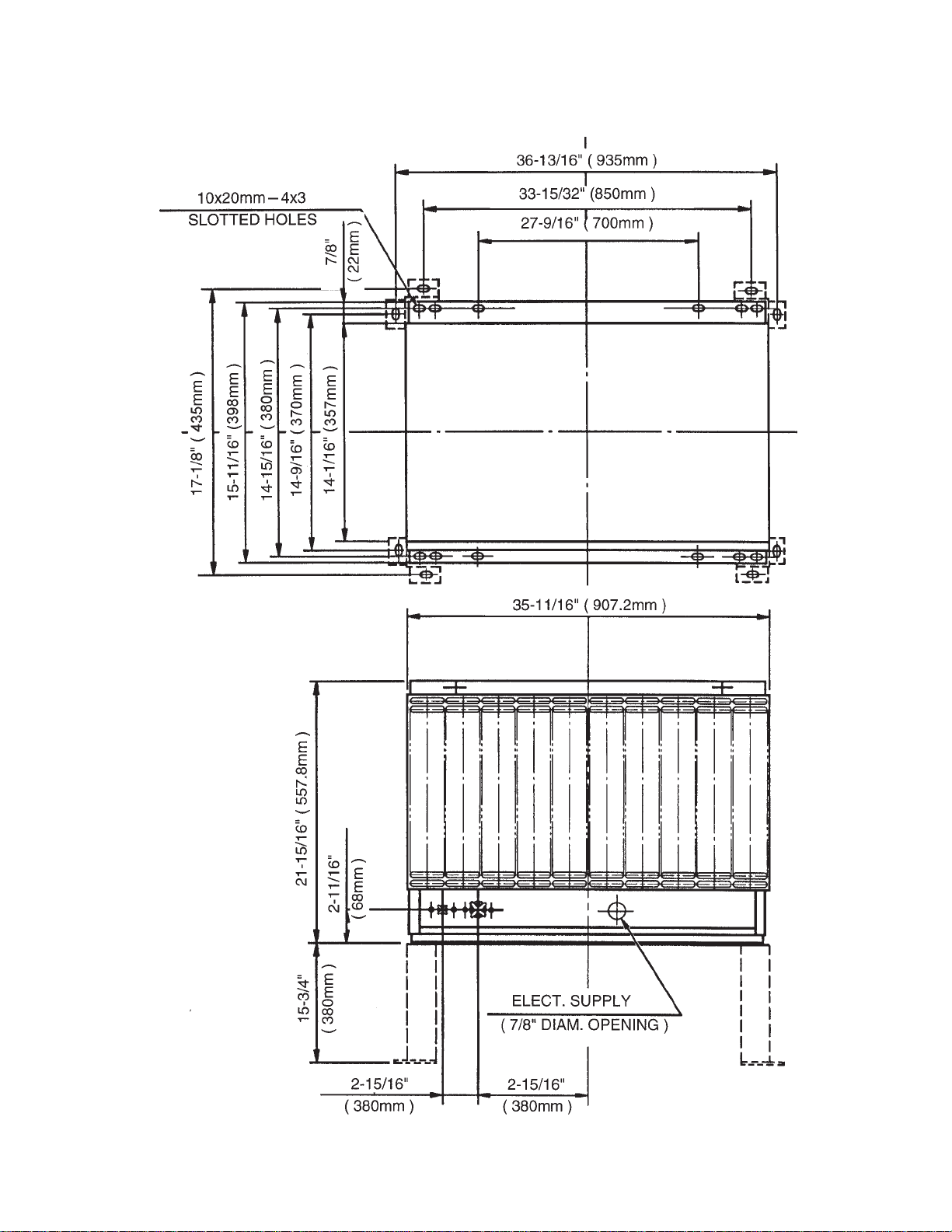
MODEL: URC-12F
Specifications
EXTERIOR
DIMENSIONS (W x D x H)
REFRIGERANT CHARGE
URC-12F
WEIGHT
CONNECTIONS
REFRIGERANT
ELECTRICAL
CONDENSER
HEAD PRESSURE CONTROL
AMBIENT CONDITION
Galvanized Steel
35 - 11/16” x 15-11/16” x 21-15/16”
(907.2 x 398 x 557.8 mm)
R404A 4 lbs. 7 oz. (2000 g)
Net 80 lbs. (36 kg)
Shipping 87 lbs. (39 kg)
One Shot Couplings (Aeroquip)
Permanent Connection
Air-cooled
Condensing Pressure Regulator
Min. -20°F - Max. +122°F
(-29°C to +50°C)
Outdoor use
12
II. General Information
1. Construction
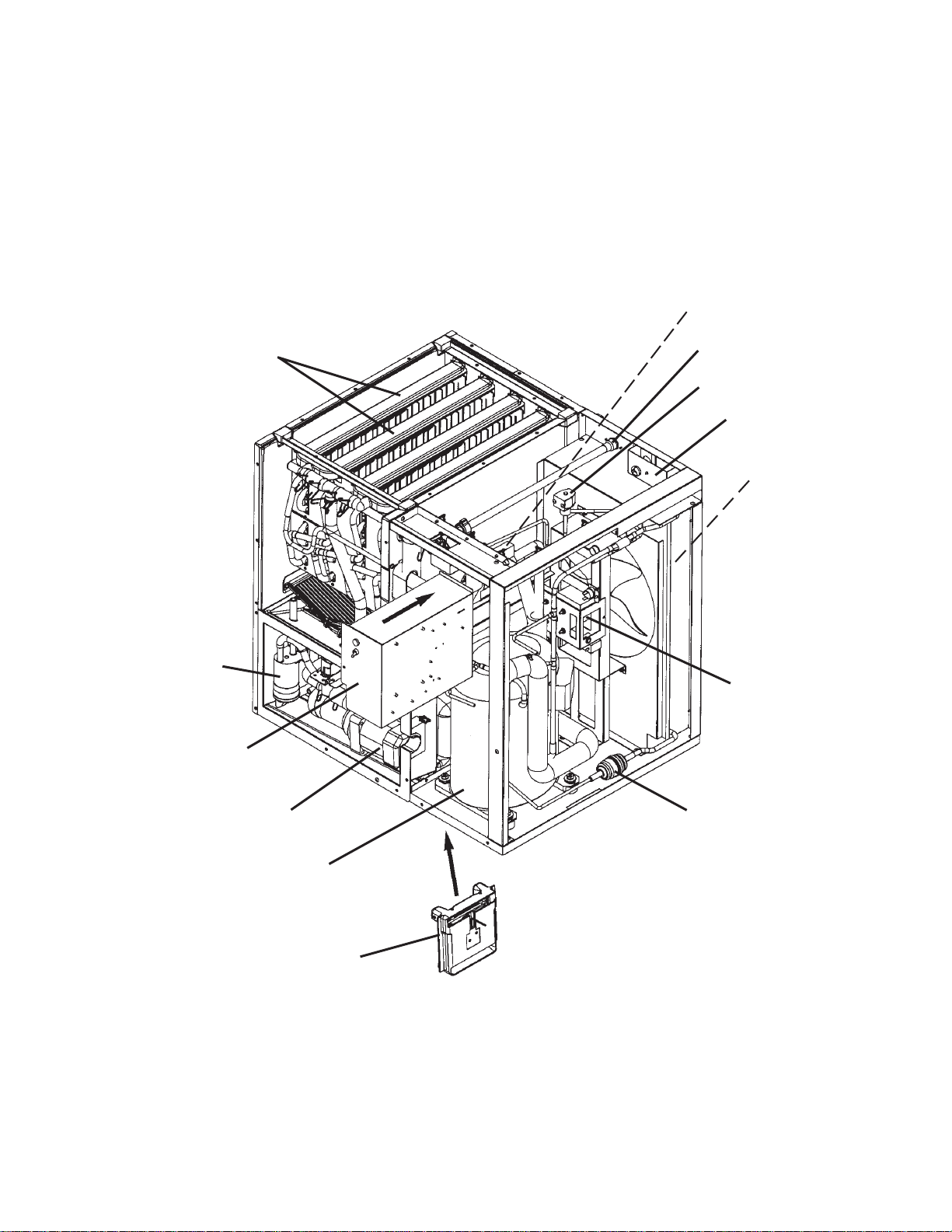
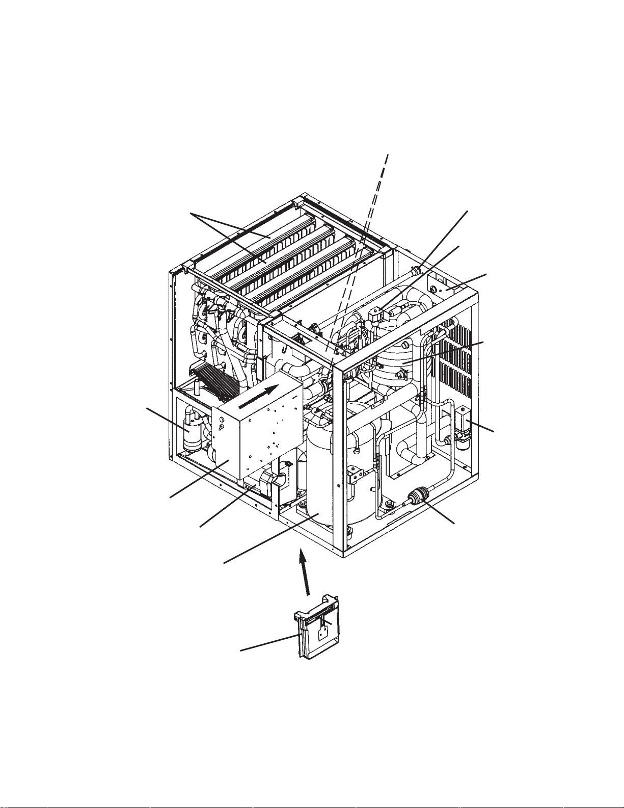
[a] KMD-700MAH
EXPANSION VALVE
SPRAY TUBE
FLOAT SWITCH
CONTROL BOX
WATER SUPPLY INLET
HOT GAS VALVE
JUNCTION BOX
CONDENSER
CONDENSER
FAN MOTOR
WATER PUMP
COMPRESSOR
BIN CONTROL
DRIER
13
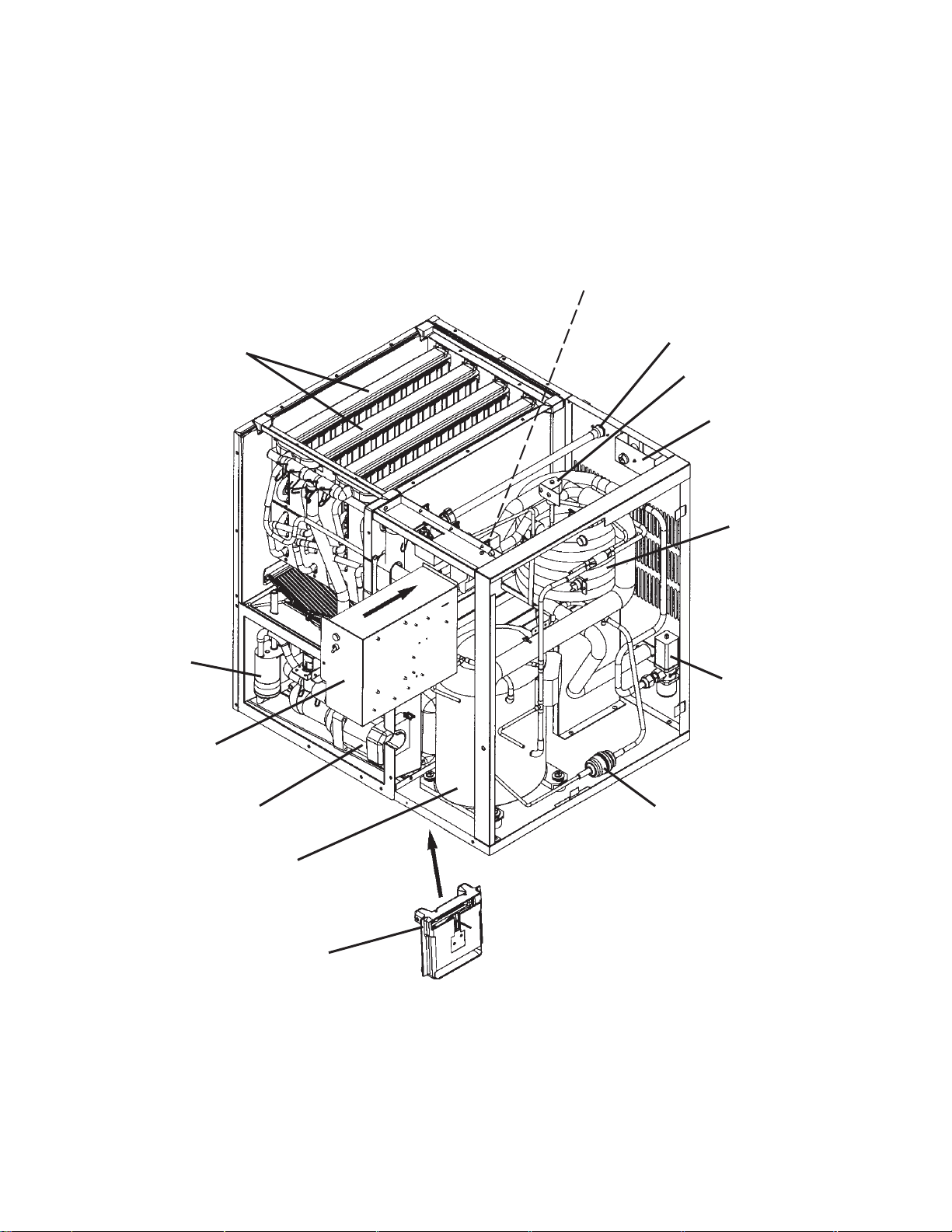
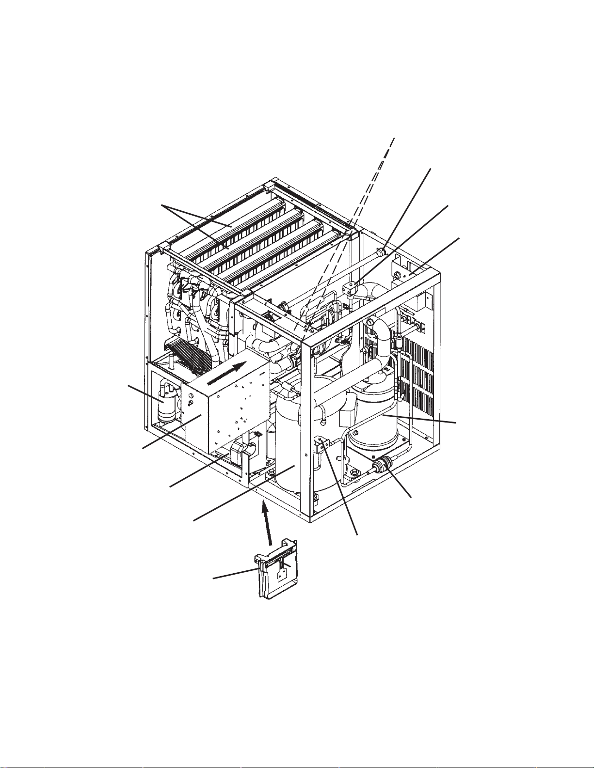
[b] KMD-700MWH
EXPANSION VALVE
SPRAY TUBE
FLOAT SWITCH
CONTROL BOX
WATER SUPPLY INLET
HOT GAS VALVE
JUNCTION BOX
CONDENSER
WATER
REGULATOR
WATER PUMP
COMPRESSOR
BIN CONTROL
DRIER
14
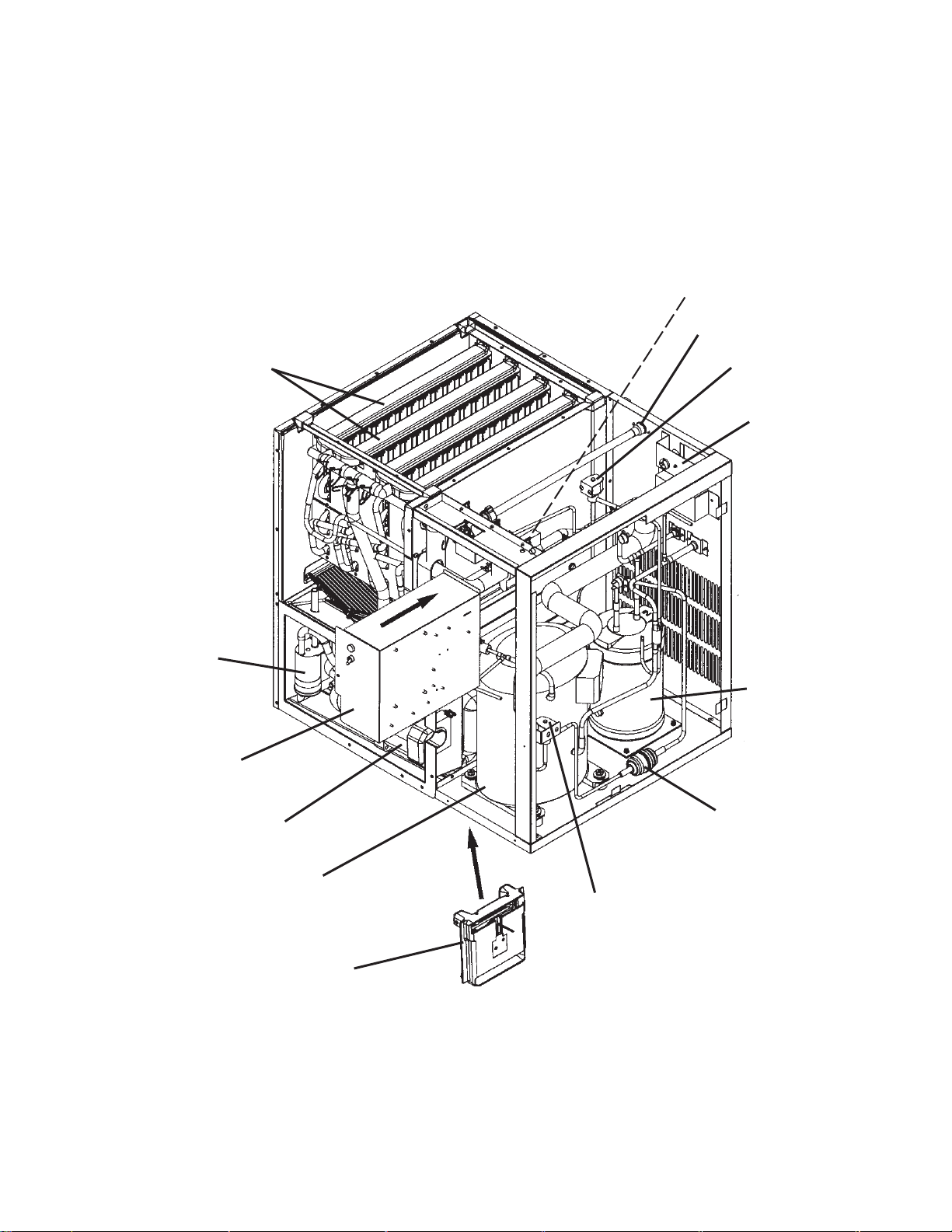
[c] KMD-700MRH
EXPANSION VALVE
WATER SUPPLY INLET
SPRAY TUBE
FLOAT SWITCH
CONTROL BOX
WATER PUMP
HOT GAS VALVE
JUNCTION BOX
RECEIVER TANK
DRIER
COMPRESSOR
BIN CONTROL
LINE VALVE
15
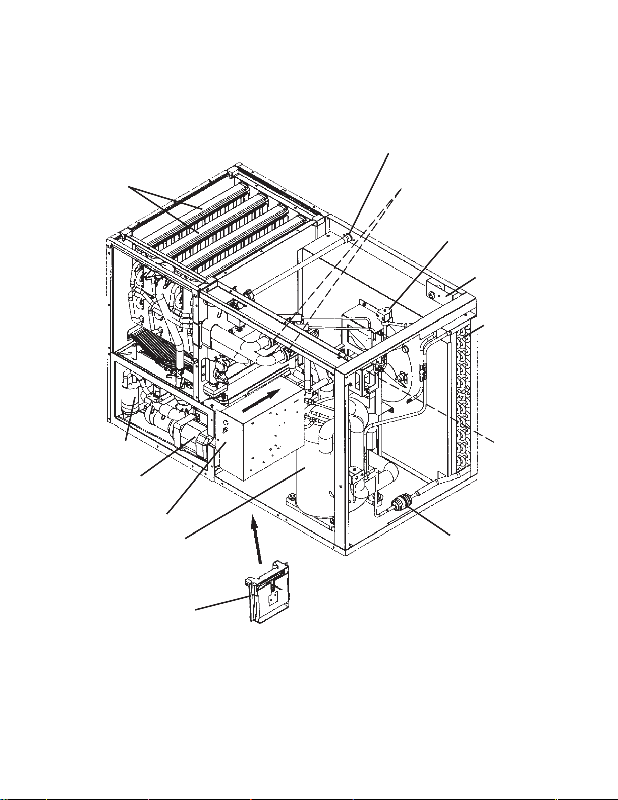
[d] KMD-900MAH
WATER SUPPLY INLET
SPRAY TUBE
FLOAT SWITCH
WATER PUMP
EXPANSION VALVE
HOT GAS VALVE
JUNCTION BOX
CONDENSER
CONDENSER
FAN MOTOR
CONTROL BOX
COMPRESSOR
BIN CONTROL
DRIER
16
[e] KMD-900MWH
EXPANSION VALVE
SPRAY TUBE
FLOAT SWITCH
CONTROL BOX
WATER SUPPLY
INLET
HOT GAS VALVE
JUNCTION BOX
CONDENSER
WATER
REGULATOR
WATER PUMP
COMPRESSOR
BIN CONTROL
DRIER
17
[f] KMD-900MRH
EXPANSION VALVE
WATER SUPPLY
INLET
SPRAY TUBE
FLOAT SWITCH
CONTROL BOX
HOT GAS VALVE
JUNCTION BOX
RECEIVER
TANK
WATER PUMP
COMPRESSOR
BIN CONTROL
DRIER
LINE VALVE
18

2. Controller Board
[a] Solid-State Control
1) A HOSHIZAKI exclusive solid-state control is employed in KMD Modular Crescent
Cubers.
2) A printed circuit board (hereafter called “controller board”) includes a stable and high
quality control system.
3) All models are pretested and factory-adjusted.
[b] Controller Board
CAUTION
1. Fragile, handle very carefully.
2. A controller board contains integrated circuits, which are susceptible to
failure due to static discharge. It is especially important to touch the metal
part of the unit when handling or replacing the board.
3. Do not touch the electronic devices on the board or the back of the board
to prevent damage to the board.
4. Do not change wiring and connections. Do not misconnect K3, K4 and
K5, because the same connector is used for the thermistor (white), float
switch (black), and mechanical bin control (red).
5. Always replace the whole board assembly when it goes bad.
6. Do not short out power supply to test for voltage.
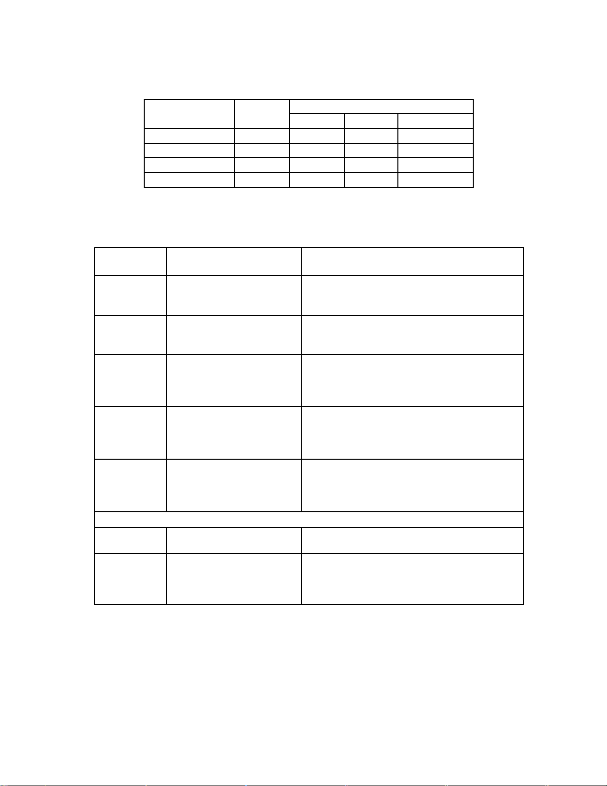
Part Number Type
2A1410-01 HOS-001A (Control Products)
Features of Control Products “E” Controller Board
1) Maximum Water Supply Period - 6 minutes
Water solenoid valve opening, in the defrost (harvest) cycle, is limited by the defrost
timer. The water valve cannot remain open longer than the maximum period. The
water valve can close in less than six minutes if the defrost cycle is completed.
19

2) Defrost Timer
The defrost cycle starts when the float switch opens and completes the freeze cycle. But
the defrost timer does not start counting until the thermistor senses 48°F at the evaporator
outlet. The period from the end of the freeze cycle up to the point of the thermistor's
sensing varies depending on the ambient and water temperatures.
3) High Temperature Safety - 127 ± 7°F
The temperature of the suction line in the refrigerant circuit is limited by the high
temperature safety.
During the defrost cycle the evaporator temperature rises. The thermistor senses
48°F and starts the defrost timer. After the defrost timer counts down to zero, the
normal freeze cycle begins. If the evaporator temperature continues to rise, the
thermistor will sense the rise in temperature and at 127 ± 7°F the thermistor
operates the high temperature safety.
This high temperature safety shuts down the circuit and the icemaker automatically stops.
This high temperature safety protects the unit from excessive temperature. The control
board will beep every 3 seconds. The white reset button on the control board must be
pressed with power on to reset the safety.
4) Low Water Safety
If the pump motor is operated without water, the mechanical seal can fail. To prevent this
type of failure, the controller board checks the position of the float switch at the end of the
initial one minute water fill cycle and at the end of each defrost cycle.
If the float switch is in the up position (electrical circuit closed), the controller board
changes to the ice making cycle. If the float switch is in the down position (electrical circuit
open), the controller board changes to a one minute water fill cycle before starting the ice
making cycle. This method allows for a low water safety shut down to protect the water
pump from mechanical seal failure.
For water-cooled model, if the water is shut off, the unit is protected by the high pressure
switch.
5) High Voltage Cutout
The maximum allowable supply voltage of this icemaker is limited by the high voltage cutout.
If miswiring (especially on single phase 3 wire models) causes excessive voltage on the
controller board, the high voltage cutout shuts down the circuit in 3 seconds and the icemaker
automatically stops. When the proper supply voltage is resumed, the icemaker automatically
starts running again. The control board will signal this problem using 7 beeps every 3
seconds.
6) LED Lights and Audible Alarm Safeties
The red LED indicates proper control voltage and will remain on unless a control voltage
problem occurs. At startup a 5 second delay occurs while the board conducts an internal
timer check. A short beep occurs when the power switch is turned ON or OFF.
20
The green LEDs 1-4 represent the corresponding relays and energize and sequence
5 seconds from initial startup as follows:
Time LEDs are Lit
1 Minute Fill Cycle
Harvest Cycle
Freeze Cycle
Reverse Pump Out
LEDSequence Step
460 seconds
1, 4, and 2 2 minutes 20 minutes 3 to 5 minutes
1 5 minutes 60 minutes 30 to 35 minutes
1, 3, and 2 10 seconds 20 seconds fac tory setting
Min. Max. Avg.
{LED 1 – Comp; LED 2 - HGV/CFM; LED 3 – PM; LED 4 - WV}
The built in safeties shut down the unit and have alarms as follows:
No. of Beeps
(every 3 sec.)
1 High Evaporator Temp.
(temperature > 127°F)
2 Defrost Backup Timer
(defrost > 20 min.)
3 Freeze Backup Timer
(freeze > 60 min.)
4 Short Circuit
(between the K4 connection
on the control board and the
bin control relay)
5 Open Circuit
(between the K4 connection
on the control board and the
bin control relay)
To manually res et the above safeties, press the white alarm reset button with the power supply on.
6Low Voltage
(92Vac or less)
7 High Voltage
(control voltage
> 147Vac ±5%)
Type of Alarm Notes
Check for defrost problem (stuck HGV or relay),
hot water entering unit, stuc k headmaster, or
shorted thermistor.
Orange LED marked 20 MIN lights up.
Check for open thermistor, HGV not opening, TXV
leaking by, low charge, or inefficient compressor.
Yellow LED marked 60 MIN lights up.
Check for F/S stuck closed (up), WV leaking by,
HGV leaking by, TXV not feeding properly, low
charge, or inefficient compressor.
Check connec tions and replace wire harness if
necessary.
Check connec tions and replace wire harness if
necessary.
Red LED will turn off if voltage protection
operates.
The voltage safety automatically resets when
voltage is corrected.
The Output Test switch “S3” provides a relay sequence test. With power OFF, place S3
ON and switch power to ICE. The correct lighting sequence should be none, 2, 3, 4, 1, & 4,
normal sequence every 5 seconds. (The LEDs are not in numerical order on the board. See
the diagram on the next page for the location and numbering of LEDs). S3 should remain in
the “OFF” position for normal operation.
21
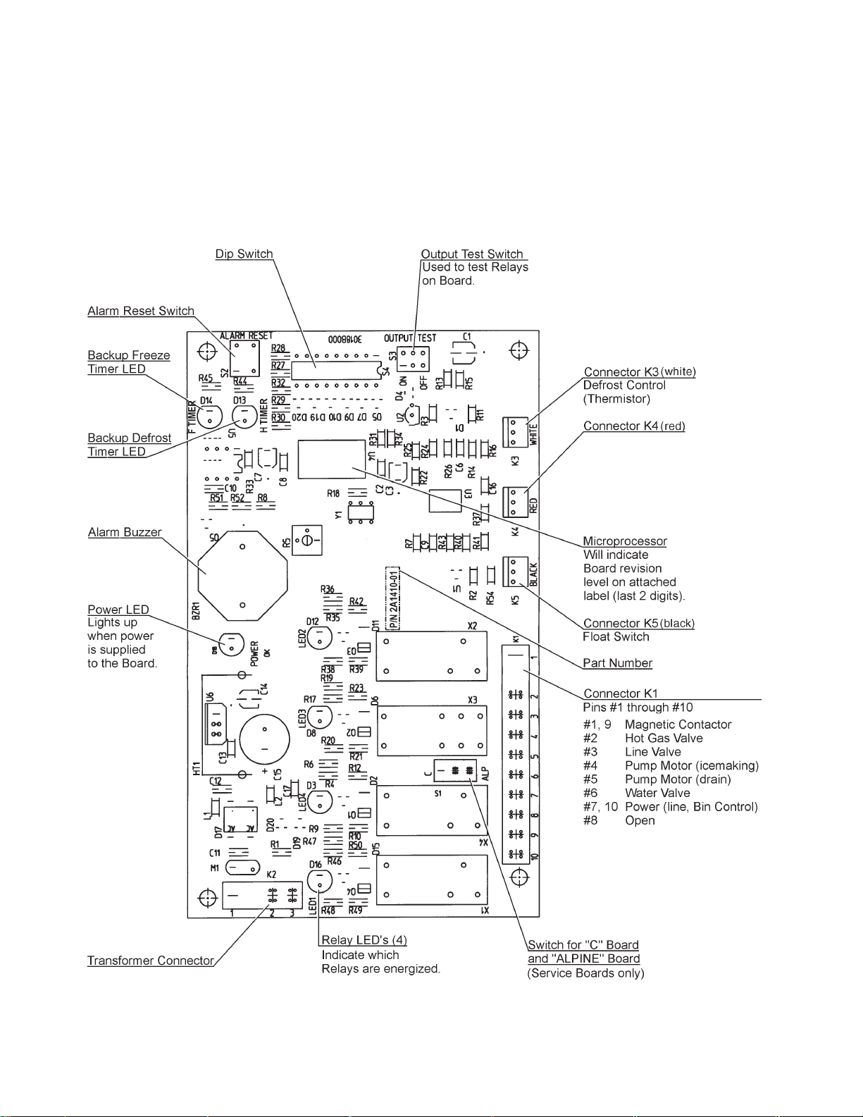
The application switch located between relay X3 & X4 must be set to match the original
board application. Place this switch in the ALP position if there is no white wire supplied to
the K1 connector. If there is a white wire, place the switch in the C position. If this switch is
placed in the wrong position, either the compressor contactor will remain energized with the
control switch OFF, or the unit will not start.
The dip switches should be adjusted per the adjustment chart published in the Tech Specs
book. Number 8 must remain in the OFF position.
(Control Products HOS-001A Board)
22
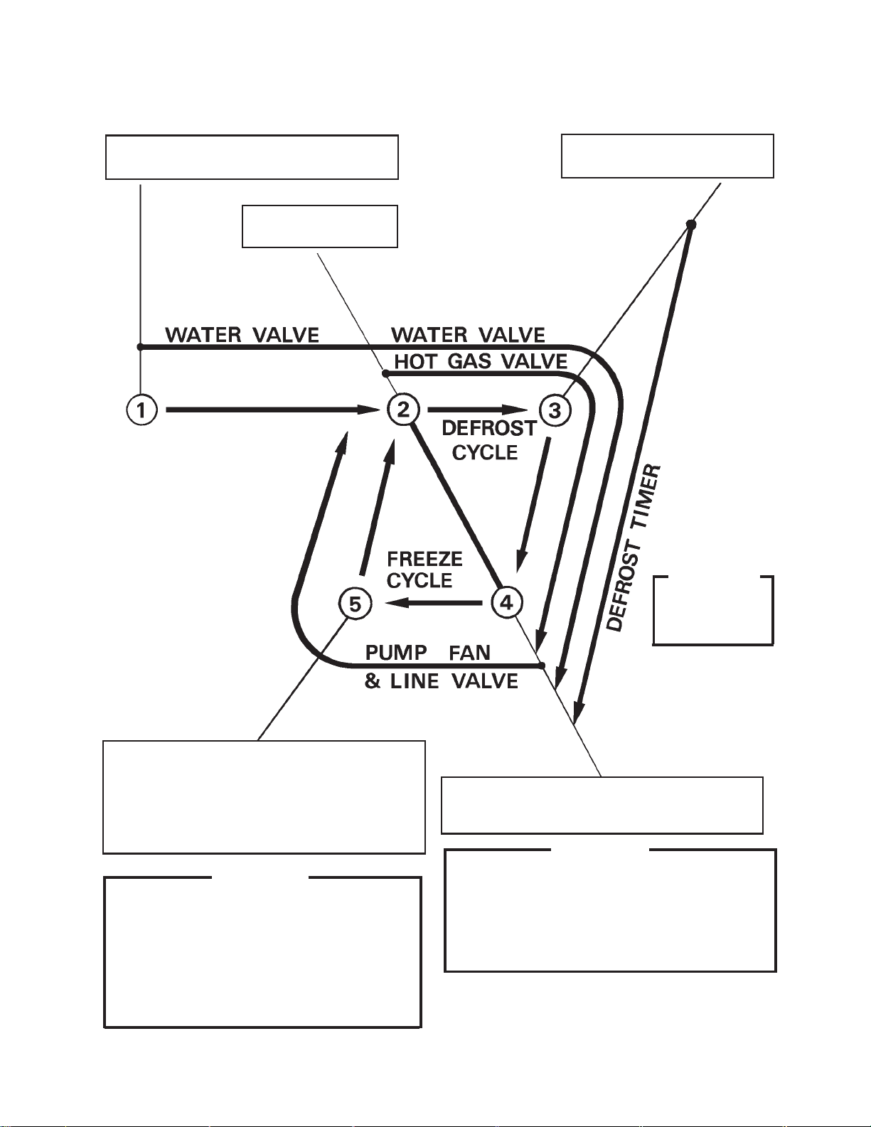
[c] Sequence
1st Cycle
1. Unit energized and control switch to “ICE”
position. Water supply cycle starts.
2. After 1 minute,
defrost cycle starts.
3. Thermistor reads 48°F.
Defrost timer starts counting.
5. After first 5 minutes in freeze cycle, cycle can
complete when float switch circuit opens.
If bin control signals that bin is full within first
5 minutes in freeze cycle, the machine will shut
down.
IMPORTANT
1. Board never accepts freeze completion signal
from float switch within first 5 minutes in freeze
cycle.
2. If bin control signals that bin is full after first
5 minutes in freeze cycle, board will allow
machine to complete freeze cycle and following
harvest cycle.
IMPORTANT
Water valve
opening is limited
to 6 minutes.
&
4. Defrost timer stops counting.
Defrost cycle is completed and freeze cycle
starts.
IMPORTANT
1. Board never accepts defrost completion
signal within the first 2 minutes in defrost
cycle.
2. Defrost cycle time is limited to 20 minutes
even if defrost timer does not stop counting.
23
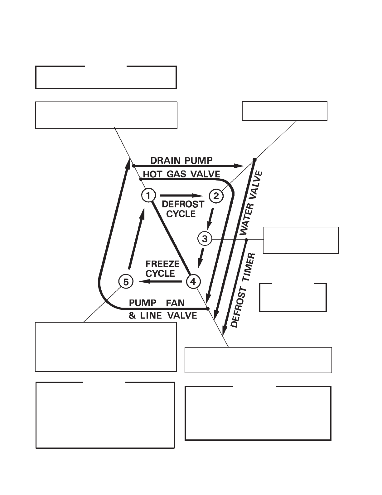
2nd Cycle and after with pump drain
IMPORTANT
Freeze cycle time is limited to 60 minutes even
if float switch does not open.
1. Float switch opens and signals to complete
freeze cycle.
Drain timer starts counting.
&
2. Drain timer stops counting.
Pump drain is completed
3. Thermistor reads 48°F.
Defrost timer starts
counting.
IMPORTANT
Water valve
opening is limited to 6
minutes.
5. After first 5 minutes in freeze cycle, cycle can
complete when float switch circuit opens.
If bin control signals that bin is full within first
5 minutes in freeze cycle, the machine will shut
down.
IMPORTANT
1. Board never accepts freeze completion signal
from float switch within first 5 minutes in freeze
cycle.
2. If bin control signals that bin is full after first
5 minutes in freeze cycle, board will allow
machine to complete freeze cycle and following
harvest cycle.
4. Defrost timer stops counting.
Defrost cycle is completed and freeze cycle
starts.
IMPORTANT
1. Board never accepts defrost completion
signal within the first 2 minutes in defrost
cycle.
2. Defrost cycle time is limited to 20 minutes
even if defrost timer does not stop counting.
24
 Loading...