

Page 1
Hoshizaki America, Inc.
Hoshizaki
Stackable Crescent Cuber
Models
KM-2500SWH3
“A Superior Degree
of Reliability”
www.hoshizaki.com
KM-2500SRH3
PARTS LIST
™
Number: 71281
Issued: 9-3-2009
Page 2

CONTENTS
Auxiliary Codes ...................................................................................................................... 3
Note About Ordering Parts .................................................................................................... 3
Material Abbreviations ........................................................................................................... 4
A. Ice Cuber Assembly .......................................................................................................... 5
KM-2500SWH3 ................................................................................................................. 5
KM-2500SRH3 .................................................................................................................. 7
B. Refrigeration Circuit ........................................................................................................... 9
KM-2500SWH3 ................................................................................................................ 9
KM-2500SRH3 ............................................................................................................... 13
C. Water Circuit .................................................................................................................... 17
D. Control Box Assembly ...................................................................................................... 20
E. Label Location ................................................................................................................. 22
KM-2500SWH3 ............................................................................................................... 22
KM-2500SRH3 ................................................................................................................ 24
F. Transformer Box Assembly ............................................................................................... 26
G. Evaporator Assembly ...................................................................................................... 27
H. Pump Motor Assembly..................................................................................................... 28
J. Accessories & Packaging ................................................................................................. 29
2
Page 3

Auxiliary Codes
KM-2500SWH3 T- 0 May 2008
KM-2500SRH3 T-0 May 2008
Auxiliary Code Breakdown
The auxiliary code is the rst two characters in the serial number. The rst character
indicates the year. Years progress or regress in alphabetical order. The series runs from
"A" through "V" and the letters "I" and "O" are skipped. The second character indicates
signicant part changes within a year. Base is "0" and this number advances for each
change.
Note About Ordering Parts
Most assemblies cannot be ordered as complete units; parts in the assemblies generally
must be ordered separately.
3
Page 4

Material Abbreviations
ALUMINUM
AL = Aluminum
COPPER
CU = Copper
PLASTIC
ABS = Acrylonitrile -butadiene - styrene
AC = Polyacetal
EVA = Ethylene vinyl acetate
PA = Polyamide = Nylon
PC = Polycarbonate
PE = Polyethylene
PES = Polyester
PETP = Polyethylene terephthalate = Tetlon
PP = Polypropylene
PS = Polystyrene
PTFE = Polytetrauoroethylene = Teon
PUR = Polyurethane
PVC = Polyvinyl chloride
RUBBER
VN = Vinyl Nitrile
EPDM = EP rubber
NBR = Nitrile butadiene rubber
NR = Natural rubber
NP = Neoprene
SI.R = Silicone rubber
SY.R = Synthetic rubber
EPH = Epichlorohydrin
STEEL
GS = Galvanized steel
SS = Stainless steel
PS = Plated steel
PAS = Primed steel
4
Page 5
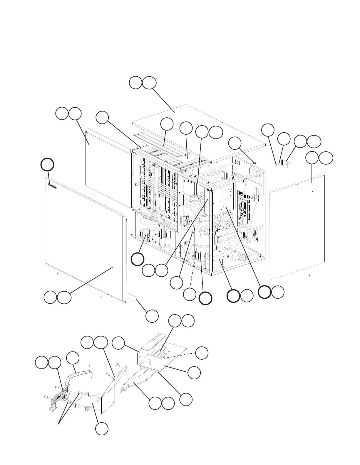
A. Ice Cuber Assembly
KM-2500SWH3
T- 0
10
19
9
E
16
16a
15
13
11
11a
21
18
23
17
17a
12
12a
26a
26
1a
1
See "J. Accessories
& Packaging"
20
14
14a
Bin Thermostat
3
C
8a
8
24
D1
19
B
22
5
2a
2
6a
6
7
4
25
5
F
F1
D
Page 6

Title: A. Ice Cuber Assembly Model: KM-2500SWH3
Index
No. Description
B Refrigeration Circuit - 1A1556A01 1
C Water Circuit - 1A1542A01 1
D Control Box Assembly - 2A2527A02 1
D1 T2 Screw 4×8 7P31-0408 3
E Label Location - 2A4667A01 1
F Transformer Box Assembly - 3A1102A01 1
F1 Truss Head Screw 4×8, SS 7C32-0408 4
1 Bulb Holder - 3A3903-01 1
1a Truss Head Screw 4×10, SS 7C32-0410 2
2 Bulb Holder (C) - 216340G01 1
2a Truss Head Screw 4×12, SS 7C32-0412 2
3 Bulb Holder (C) (For mounting
hardware, see section "J"
item 3)
4 Bulb Holder (E) GS 439725-01 1
5 Bulb Holder (F) GS 328743-01 1
6 Bulb Holder (G) GS 439726-01 1
6a Truss Head Screw 4×6, SS 7C32-0406 2
7 Capillary Ring - 425307-01 1
8 Control Box Cover GS 3A2386-01 1
8a T2 Screw 4×8 7P31-0408 2
9 Evaporator Case - 2A2100G05 1
10 Front Insulation - 326041G01 1
11 Front Panel Bracket SS 323903-01 1
11a T2 Screw 4×12, SS 7P32-0412 2
12 Side Panel (R) SS 215381G02 1
12a Truss Head Screw 4×8, SS 7C32-0408 1
13 Spacer - 324321-01 1
14 Thermostat Extension Bracket SS 3A0408-01 1
14a T2 Screw 4×12, SS 7P32-0412 2
15 Top Insulation - 324216G01 1
16 Top Panel SS 2A2255-01 1
16a Truss Head Screw 4×8, SS 7C32-0408 2
17 Junction Box Cover GS 433410-01 1
17a T2 Screw 4×8 7P31-0408 2
18 Square Washer BRASS 433537-02 1
19 Thumbscrew BLACK 415949G12 3
20 Silicone Hose L=285 7730I3812 1
21 Bushing SR-31-2 420472-08 1
22 Gasket L=1219 4A0808L02 1
23 Screw-Grounding M5×8 433304-02 1
24 Clamp - 4A0337-12 1
25 Spacer - 439727-01 1
26 Front Panel - 3A1838G01 1
26a Truss Head Screw 4×16, SS 7C32-0416 2
Material or
Model Number Part Number
Z Bracket 325845G01 1
Required Number
T- 0
6
Page 7
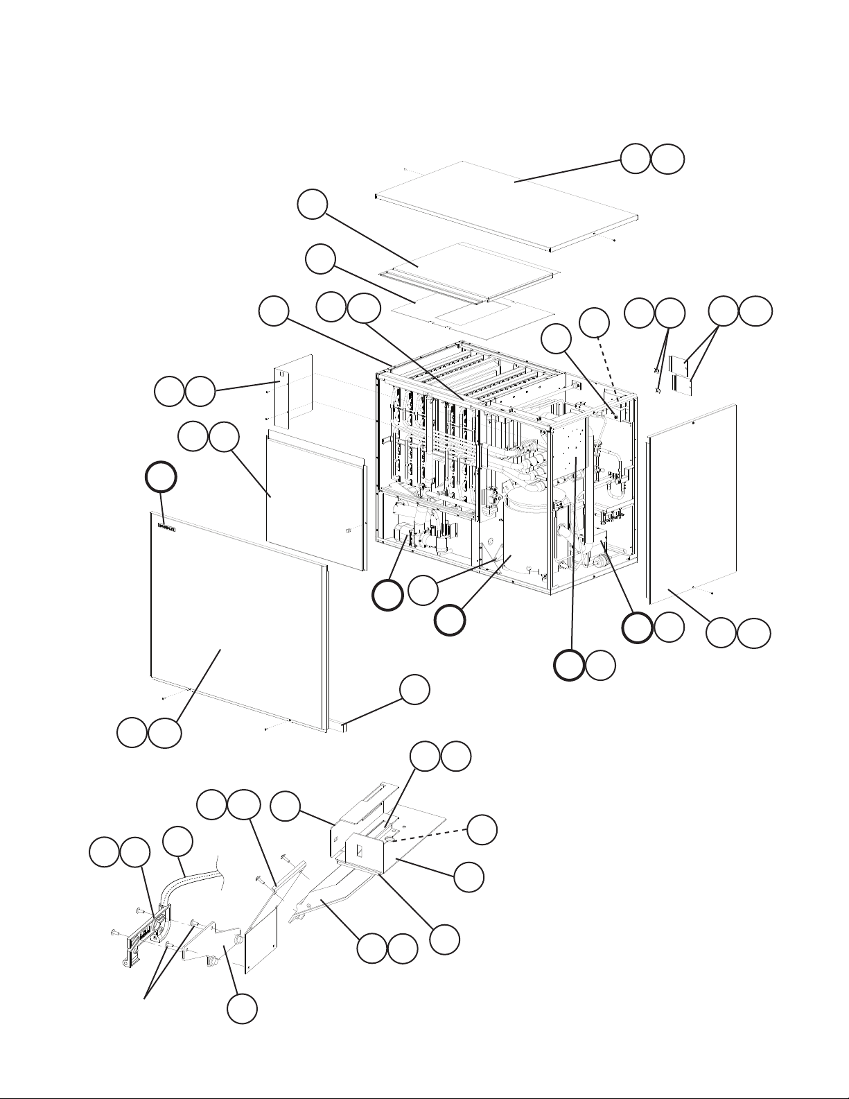
A. Ice Cuber Assembly
KM-2500SRH3
T- 0
9
8a
8
10
20
E
16
13
11
11a
22
23
17a
17
19 25
18
18a
20
C
B
D1
D
24
26a
26
6a
6
15a
15
1a
1
21
5
Bin Thermostat
7
4
2a
2
14
F
F1
12
12a
See "J. Accessories
& Packaging"
3
7
Page 8

Title: A. Ice Cuber Assembly Model: KM-2500SRH3
Index
No. Description
B Refrigeration Circuit - 1A1546A01 1
C Water Circuit - 1A1542A01 1
D Control Box Assembly - 2A2527A02 1
D1 T2 Screw 4×8 7P31-0408 3
E Label Location - 2A4632A01 1
F Transformer Box Assembly - 3A1102A01 1
F1 Truss Head Screw 4×8, SS 7C32-0408 4
1 Bulb Holder - 3A3903-01 1
1a Truss Head Screw 4×10, SS 7C32-0410 2
2 Bulb Holder (C) - 216340G01 1
2a Truss Head Screw 4×12, SS 7C32-0412 2
3 Bulb Holder (C) (For mounting
hardware, see section "J"
item 3)
4 Bulb Holder (E) GS 439725-01 1
5 Bulb Holder (F) GS 328743-01 1
6 Bulb Holder (G) GS 439726-01 1
6a Truss Head Screw 4×6, SS 7C32-0406 2
7 Capillary Ring - 425307-01 1
8 Control Box Cover - 3A2386-01 1
8a T2 Screw 4×8 7P31-0408 2
9 Evaporator Case - 2A2100G05 1
10 Front Insulation - 326041G01 1
11 Front Panel - Bracket SS 323903-01 1
11a T2 Screw 4×12, SS 7P32-0412 2
12 Side Panel (R) - 215381G02 1
12a Truss Head Screw 4×8, SS 7C32-0408 1
13 Spacer - 324321-01 1
14 Spacer - 439727-01 1
15 Thermostat Extension Bracket SS 3A0408-01 1
15a T2 Screw 4×12, SS 7P32-0412 2
16 Top Insulation - 324216G01 1
17 Top Panel - 2A2255-01 1
17a Truss Head Screw 4×8, SS 7C32-0408 2
18 Junction Box Cover GS 433410-01 2
18a T2 Screw 4×8 7P31-0408 2
19 Square Washer BRASS 433537-02 2
20 Thumbscrew BLACK 415949G12 3
21 Silicone Hose 3/8 × 1/2,
22 Bushing SR-30-1 420472-03 1
23 Bushing SR-31-2 420472-08 1
24 Gasket L=1219 4A0808L02 4
25 Screw Grounding M5×8 433304-02 2
26 Front Panel - 3A1838G01 1
26a Truss Head Screw 4×16, SS 7C32-0416 2
Material or
Model Number Part Number
Z Bracket 325845G01 1
7730I3812 1
L=285
Required Number
T- 0
8
Page 9
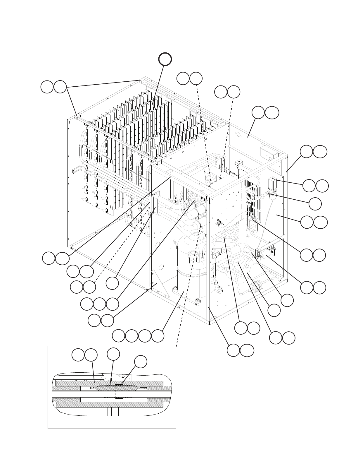
B. Refrigeration Circuit
1/2
KM-2500SWH3
T- 0
G2
G1
G
37 38
35
36
31
31a
34
34a
5a
5
6
30
30a
40a
40
41 42
27
49
32a
32
29
49
63
10
9
3a
3
2524
49
2a
2
4a
4
28
1c
33
33a
1a11b
26
7
8
Detailed Expansion Valve Bulb
9
Page 10

B. Refrigeration Circuit
2/2
KM-2500SWH3
T- 0
44
50
50a
46
50b
43
43a
45
59
15
14
13
12
19
54
23
39
47
47a
48
50
50a
50b
51
11
51a
22
52
18
58
21
17
61
62
60
20
56 57
61a
62a
55
49
53
Detailed Thermistor Attachment
16
10
Page 11

Title: B. Refrigeration Circuit Model: KM-2500SWH3
Index
No. Description
G Evaporator Assembly - 105103A01 1
G1 Frame Seal - 323925-01 4
G2 T2 Screw 4×12, SS 7P32-0412 4
Material or
Model Number Part Number
Required Number
T- 0
1 Compressor
1a Bolt Assembly 8x45 437889-01 4
1b Spacer - 434921-01 4
1c Grommet - 434922-01 4
2 Brace GS 325858-01 1
2a T2 Screw 4×8 7P31-0408 4
3 Condenser - Water-Cooled HS-0163 2A2359G04 2
3a Hex Bolt w/Washer (LF) 5×12 7B0130512 4
4 Water Condenser Bracket - 3A4901-01 1
4a T2 Screw 4×8 7P31-0408 2
5 Water Regulator - 4A0911-07 1
5a Truss Head Screw 4×8 7C31-0408 2
6 Male Connector - 4A1087-01 1
7 Copper Tube (A) - 3A4918G01 1
8 Insulation Tubing L=60 7762-2040 1
9 Insulation Tubing L=275 7762-2040 1
10 Insulation Tubing L=340 7762-2040 1
11 Copper Tube (A) - High Side - 3A4915-01 1
12 Copper Tube (A1) - Hot Gas - 2A4607G01 1
13 Copper Tube (A2) - Hot Gas - 2A4607G02 1
14 Copper Tube (A3) - Hot Gas - 2A4607G03 1
15 Copper Tube (B) - 4A4531G01 1
16 Copper Tube (B) - High Side - 2A4684G01 1
17 Copper Tube (B) - Low Side - 3A4843-01 1
18 Copper Tube (B2) - 4A4532-01 1
19 Copper Tube (C) - Low Side - 2A4608G01 1
20 Copper Tube (E) - High Side - 3A4916-01 1
21 Copper Tube (F) - High Side - 3A4917-01 1
22 Copper Tube (G) - High Side - 4A4540-01 1
23 Copper Tube (J) - High Side - 3A4828G01 1
24 Expansion Valve - 4A1482-01 3
25 Expansion Valve Cover - 3A0944-01 3
26 Holder Expansion Valve - 3A0107-01 3
27 Insulation Tube L=200 7762-2949 3
28 Clamp - 443461-02 3
29 Insulation Tube L=50 7762-1020 1
30 Front Frame - 3A4903-01 1
30a T2 Screw 4×8 7P31-0408 4
31 Rear Frame GS 3A4905G01 1
31a T2 Screw 4×8 7P31-0408 4
32 Rear Panel (A) - 2A4675-01 1
32a T2 Screw 4×8 7P31-0408 9
33 Side Frame (A) GS 215375G01 1
33a T2 Screw 4×8 7P31-0408 3
CS27K6E-TF5-230
4A4486-01 1
11
Page 12

Title: B. Refrigeration Circuit Model: KM-2500SWH3
Index
No. Description
34 Side Frame (B) GS 215376G01 1
34a T2 Screw 4×8 7P31-0408 2
35 Header Cover (A1) - 325861-01 1
36 Header Cover (A2) - 325861-02 1
37 Header Cover (B1) - 325862-01 1
38 Header Cover (B2) - 325862-02 1
39 Heat Exchanger - 2A4619G01 1
40 Insulation Holder SS 325863-01 1
40a T2 Screw 4×8, SS 7P32-0408 2
41 Rubber Insulation (A) - 325864-01 1
42 Rubber Insulation (B) - 325865-01 1
43 Hot Gas Valve Bracket - 442162-01 1
43a T2 Screw 4×8 7P31-0408 2
44 Valve Body - Hot Gas - 4A3978-01 1
45 Strainer - 441569-02 1
46 Check Valve Assembly - 3A4832G01 1
47 Line Valve Bracket GS 4A1406-01 1
47a T2 Screw 4×8 7P31-0408 2
48 Valve Body - Line - 4A3276-01 1
49 Cable Tie PLT-2M 8911-0200 25
50 Coil - Valve - 4A3277-01 2
50a Bolt - 4A3277F01 2
50b Truss Head Screw 4×8 7C31-0408 4
51 Pressure Switch Bracket GS 434938-01 1
51a T2 Screw 4×8 7P31-0408 1
52 Pressure Switch - 433441-05 1
53 Thermistor L=1050 429006-03 1
54 Holder - Thermistor - 438247-01 1
55 Insulation - Thermistor - 427441-01 1
56 Drier - 4A2663-01 1
57 Nylon Tie PLWP3H-TL 8911-0301 1
58 Elbow - 417395-04 2
59 Te e - 417394-04 1
60 Te e - 436000-06 1
61 Bracket - Service Valve GS 4A3872-01 1
61a T2 Screw 4×8 7P31-0408 2
62 Service Valve - 4A3420-01 2
62a Hex Head Tapping Screw 1/4-20×1/2 7B03I1412 2
63 Insulation - 436671-01 1
Material or
Model Number Part Number
Required Number
T- 0
12
Page 13

B. Refrigeration Circuit
1/2
KM-2500SRH3
T- 0
G1 G2
22
22a
17
59
27
28
29
30
25
25a
35
35a
26
26a
56
32
33
G
32a
34
73
70
21 59
47a
47
48a
48
42a
42
43
23a
23
24a
24
39a
39
71
2a
2
1
60
61
72
62
63
64 65
67
69
6866
19
59
Detailed Expansion Valve Bulb
18
20
13
Page 14

B. Refrigeration Circuit
2/2
KM-2500SRH3
T- 0
16
38
41
41a
41b
37
11
6
5
4
10
13
40
36
9
14
15
53a
53
52a
52
7
8
57a
57
58a
58
12
55
54
3
51
59
50
41a
41
44a
44
49
Detailed Thermistor Attachment
45
45a
14
46
41b
46a
31
Page 15

Title: B. Refrigeration Circuit Model: KM-2500SRH3
Index
No. Description
G Evaporator Assembly - 105103A01 1
G1 Frame Seal - 323925-01 4
G2 T2 Screw 4×12, SS 7P32-0412 4
Material or
Model Number Part Number
Required Number
T- 0
1 Compressor (includes items 60
through 69)
2 Brace GS 325858-01 1
2a T2 Screw 4×8 7P31-0408 4
3 Copper Tube (A) - High Side - 3A4915-01 1
4 Copper Tube (A1) - Hot Gas - 2A4607G01 1
5 Copper Tube (A2) - Hot Gas - 2A4607G02 1
6 Copper Tube (A3) - Hot Gas - 2A4607G03 1
7 Copper Tube (B) - High Side - 2A5011G01 1
8 Copper Tube (B) - Low Side - 3A5287-01 1
9 Copper Tube (C) - High Side - 3A3686G01 1
10 Copper Tube (C) - Low Side - 2A4608G01 1
11 Copper Tube (D) - High Side - 3A4811-01 1
12 Copper Tube (E) - High Side - 3A4933-01 1
13 Copper Tube (J) - High Side - 3A4828G01 1
14 Coupling - 433751G01 1
15 Coupling - 434136G03 1
16 Expansion Valve - 4A1482-01 3
17 Expansion Valve Cover - 3A0944-01 3
18 Holder-Expansion Valve 3/8 3A0107-01 3
19 Insulation Tube L=200 7762-2949 3
20 Clamp 443461-02 3
21 Insulation Tube L=50 7762-1020 1
22 Front Frame - 3A4903-01 1
22a T2 Screw 4×8 7P31-0408 4
23 Side Frame (A) GS 215375G01 1
23a T2 Screw 4×8 7P31-0408 3
24 Side Frame (B) GS 215376G01 1
24a T2 Screw 4×8 7P31-0408 2
25 Rear Frame GS 3A4905G02 1
25a T2 Screw 4×8 7P31-0408 4
26 Rear Panel GS 2A1700-01 1
26a T2 Screw 4×8 7P31-0408 8
27 Header Cover (A1) - 325861-01 1
28 Header Cover (A2) - 325861-02 1
29 Header Cover (B1) - 325862-01 1
30 Header Cover (B2) - 325862-02 1
31 Heat Exchanger - 2A5012G01 1
32 Insulation Holder SS 325863-01 1
32a T2 Screw 4×8, SS 7P32-0408 2
33 Rubber Insulation (A) - 325864-01 1
34 Rubber Insulation (B) - 325865-01 1
35 Hot Gas Valve Bracket GS 442162-01 1
35a T2 Screw 4×8 7P31-0408 2
36 Valve Body-Hot Gas - 4A3978-01 1
MTZ57HL3A
4A4782-01 1
15
Page 16

Title: B. Refrigeration Circuit Model: KM-2500SRH3
Index
No. Description
37 Strainer - 441569-02 1
38 Check Valve Assembly - 3A4832G01 1
39 Line Valve Bracket GS 4A1406-01 1
39a T2 Screw 4×8 7P31-0408 2
40 Valve Body-Line - 4A3276-01 1
41 Coil-Valve - 4A3277-01 2
41a Bolt - 4A3277F01 2
41b Truss Head Screw 4×8 7C31-0408 4
42 Pressure Switch Bracket GS 434938-01 1
42a T2 Screw 4×8 7P31-0408 1
43 Pressure Switch - 433441-07 1
44 Receiver Tank - 440366-01 1
44a Hex Bolt w/Washer (LF) 5×10 7B0130510 3
45 Receiver Bracket (A) GS 327093-01 1
45a T2 Screw 4×8 7P31-0408 2
46 Receiver Bracket (B) GS 440860-01 1
46a T2 Screw 4×8 7P31-0408 1
47 Valve Bracket - 4A4505-01 1
47a T2 Screw 4×8 7P31-0408 2
48 Shutoff Valve - 4A2215-01 1
48a Hex Head Bolt 1/4×20×1/2 7B01I1420 1
49 Thermistor L=1050 429006-03 1
50 Thermistor Holder - 438247-01 1
51 Thermistor Insulation - 427441-01 1
52 Tube Holder-L GS 438245-01 1
52a T2 Screw 4×8 7P31-0408 2
53 Tube Holder-S GS 438246-01 1
53a T2 Screw 4×8 7P31-0408 2
54 Drier - 4A2663-01 1
55 Nylon Tie PLWP3H-TL 8911-0301 1
56 CP Regulator (Headmaster) LAC-4-190 4A0229-01 1
57 Bracket-Service Valve GS 4A3872-01 1
57a T2 Screw 4×8 7P31-0408 2
58 Service Valve - 4A3420-01 3
58a Hex Head Tapping Screw 1/4-20×1/2 7B03I1412 3
59 Cable Tie - 8911-0200 25
60 Compressor Mounting Kit - 4A4782F02 1
61 Crankcase Heater 9HT5-35 4A2090-01 1
62 Crankcase Seal - 4A2090F01 1
63 Discharge Fitting - 4A4782F04 1
64 Discharge Nut - 4A2089-01 1
65 Discharge Teon Ring - 4A4782F06 1
66 Suction Fitting - 4A4782F03 1
67 Suction Nut - 4A2088-01 1
68 Suction Teon Ring - 4A4782F05 1
69 Terminal Cover Kit - 4A4782F01 1
70 Top Compressor Insulation - 4A2078-01 1
71 Right Compressor Insulation - 4A2079-01 1
72 Left Compressor Insulation - 4A2080-01 1
73 Insulation - 436671-01 1
Material or
Model Number Part Number
Required Number
T- 0
16
Page 17

C. Water Circuit
KM-2500SWH3, KM-2500SRH3
T- 0
38
37
18
10
16
10a
52
52
21
51
11
50
20
12
13
45
50
42
33
41
52
44
17
53
14
6
50
27
23
15
25
19
28
32
31
30
4
2
50
55
4a
50
39
56
3
54
48
1
3a
55
5
48a
40
1a
56
7
40a
7a
26
29
5
24
H
H1
47
35
22
43
35a
36
46
17
34
34a
8
49
9
Page 18

Title: C. Water Circuit Model: KM-2500SWH3, KM-2500SRH3
Index
No. Description
H Pump Motor Assembly S-0730 215692A03 1
H1 Truss Head Screw 5×8, SS 7C32-0508 2
1 Water Supply Pipe COPPER 4A0768G04 1
1a T2 Screw 4×8 7P31-0408 2
2 Rubber Gasket SI.R 413854-03 1
3 Water Valve Bracket GS 3A2685-01 1
3a T2 Screw 4×8 7P31-0408 1
4 Water Valve - 4A1176-04 1
4a Truss Head Screw 4×8, SS 7C32-0408 2
5 Cube Guide 26144 214243-01 2
6 Separator (A) - 215046-01 2
7 Handle - 215383-01 1
7a T2 Screw 4×8 7P31-0408 1
8 Drain - 309246-01 1
9 "O" Ring - 7611-P015 1
10 Valve Housing-Drain - 323613-01 1
10a T2 Screw 4×10, SS 7P32-0410 3
11 Valve Seat - 433705-01 1
12 Spring - 322110-01 1
13 "O" Ring - 7611-G035 1
14 Joint-Overow - 323923-02 1
15 "O" Ring - 7611-P018 1
16 Distributor Hose (A) - 325738-01 1
17 Distributor Hose (B) - 325738-02 1
18 Distributor Hose (C) - 325739-01 2
19 Overow Cap - 325866-01 1
20 Hose (B) - 325867-01 1
21 Drain Hose - 325869-01 1
22 Hose (A) - 435091-01 1
23 Bypass Hose - 439237-02 1
24 Distributor (C) - 439238-01 1
25 Distributor (B) - 439239-01 1
26 Distributor (A) - 439266-01 1
27 Flange - 439267-02 1
28 Vinyl Hose L=40 7716-1216 1
29 Joint Pipe - 439297-01 1
30 Joint Hose - 439309-01 1
31 Corner Insulation (A) - 439376-01 1
32 Corner Insulation (B) - 439392-01 1
33 Separator (B) - 2A0100-01 2
34 Float Switch Bracket SS 3A0449-01 1
34a T2 Screw 4×8, SS 7P32-0408 2
35 Float Switch 213095 4A3624-01 1
35a Truss Head Screw 4×10, SS 7C32-0410 2
36 Connector-Float Switch - 426799-04 1
37 Spray Tube - 437049G01 6
38 Spray Guide (A) - 208586-01 18
39 Wire Saddle - 4A0338-02 8
Material or
Model Number Part Number
Required Number
T- 0
18
Page 19

Title: C. Water Circuit Model: KM-2500SWH3, KM-2500SRH3
Index
No. Description
40 Valve Holder - 3A1178-01 1
40a Truss Head Screw 4×8 7C31-0408 3
41 Vinyl Hose L=230 7716-2732 1
42 Vinyl Hose L=550 7716-2732 1
43 Insulation Tube L=120 7762-3555 1
44 Insulation Tube L=130 7762-3555 1
45 Insulation Tube L=200 7762-3555 1
46 Silicone Hose L=190 7730I3812 1
47 Silicone Hose L=430 7730I3896 1
48 Microswitch V7-ICI7D8-207 4A2546-01 1
48a Tapping Screw 3×14 431415-02 2
49 Bushing SB-1500-21 420470-06 2
50 Hose Clamp 25 mm, SS 427443-03 9
51 Hose Clamp 13.5 mm, SS 427443-07 6
52 Hose Clamp 32 mm, SS 427443-09 6
53 Clamp No. 4253 427902-05 1
54 Ball Valve (Included in S-0761) P VC 439293-01 1
55 Male Adaptor (Included in
S-0761)
56 "O" Ring (Included in S-0761) - 7611-P018 2
Material or
Model Number Part Number
ABS 325826-01 2
Required Number
T- 0
19
Page 20

D. Control Box Assembly
KM-2500SWH3, KM-2500SRH3
T- 0
16
2
12
14
1
2a
3a
3
18
17
8
9
5
4
15
11
13
19
19a
10
7a
7
6
18
9
20
Page 21

Title: D. Control Box Assembly Model: KM-2500SWH3, KM-2500SRH3
Index
No. Description
1 Control Box GS 2A2524G02 1
2 Magnetic Contactor - 4A0794-01 1
2a Truss Head Screw 4×12 7C31-0412 2
3 Transformer - 3A0172-01 1
3a T2 Screw 4×8 7P31-0408 2
4 Board Support - 4A0336-03 4
5 Control Board - 2A1410-01 1
6 Control Label - 4A1758-01 1
7 Thermostat - 4A2879-02 1
7a Truss Head Screw 4×6 7C31-0406 2
8 Fuse Holder - 4A3449-01 1
9 Fuse AGC-10 4A0893-07 2
10 Toggle Switch - 443119-01 1
11 Plug Housing 3P 3191-03P 412832-06 1
12 Plug Housing 2P 3191-02P 412832-07 1
13 Receptacle Housing 3P 3191-03R1 412831-06 1
14 Receptacle Housing 2P 3191-02R1 412831-07 1
15 Bushing - 420470-03 1
16 Bushing - 420470-12 1
17 Bushing - 428394-02 1
18 Bushing - 428394-04 2
19 Capacitor 15 MFD, 250V 439705-01 1
19a T2 Screw 4×10 7P31-0410 1
Material or
Model Number Part Number
T- 0
Required Number
21
Page 22

E. Label Location
KM-2500SWH3
T- 0
13
A
11
1
18
15
16
5
3
6
4
14
7
17
2
12
8
9
10
Detail Control Box
View "A"
22
Page 23

Title: E. Label Location Model: KM-2500SWH3
Index
No. Description
1 Emblem - 4A0560-01 1
2 Label - Fuse - 4A2817-01 1
3 Label - Penguin - HA - R - 4A0526-01 1
4 Maintenance Label - 3A3922-01 1
5 Caution Label - K - 439150-01 1
6 Label - R404A - 4A0960-01 1
7 Label - Alarm - 4A3517-01 1
8 Nameplate - 2A4633-02 1
9 Wiring Label - 3A4813-01 1
10 Manual Label - 324476-01 1
11 Manual Label - Bin Control - 3A4844-01 1
12 Tag Warning Electrical
Connection
13 Instruction Sheet - 4A4709-01 1
14 Instruction Label - 444575-01 1
15 Operation Label - Valve - 439541-01 1
16 Rating Label - 2A4634-02 1
17 Label - Control Board - 3A2220-01 1
18 Process Valve Label (A) - 4A3943-01 1
Material or
Model Number Part Number
- 438479-01 1
Required Number
T- 0
23
Page 24

E. Label Location
KM-2500SRH3
T- 0
1
13
A
11
18
15
16
5
3
6
4
7
2
17
14
12
8
9
Detail Control Box
10
19
6
20
View "A"
24
Page 25

Title: E. Label Location Model: KM-2500SRH3
Index
No. Description
1 Emblem - 4A0560-01 1
2 Label - Fuse - 4A2817-01 1
3 Label - Penguin - HA - R - 4A0526-01 1
4 Maintenance Label - 3A3922-01 1
5 Caution Label - K - 439150-01 1
6 Label - R404A - 4A0960-01 2
7 Label - Alarm - 4A3517-01 1
8 Nameplate - 2A4633-01 1
9 Wiring Label - 3A4813-01 1
10 Manual Label - 324476-01 1
11 Manual Label - Bin Control - 3A4844-01 1
12 Tag Warning Electrical
Connection
13 Instruction Sheet - 2A4709-01 1
14 Instruction Label - 444575-01 1
15 Operation Label - Valve - 439541-01 1
16 Rating Label - 2A4634-01 1
17 Label - Control Board - 3A2220-01 1
18 Process Valve Label (A) - 4A3943-01 1
19 Tag - Fan Motor Leads - 4A1494-01 1
20 Caution - Remote Label - 4A1422-01 1
Material or
Model Number Part Number
- 438479-01 1
Required Number
T- 0
25
Page 26

F. Transformer Box Assembly
KM-2500SWH3, KM-2500SRH3
T- 0
1
2
2a
5
3
4
6
Title: F. Transformer Box Assembly Model: KM-2500SWH3, KM-2500SRH3
Index
No. Description
1 Transformer Box GS 3A1101-01 1
2 Transformer Box Cover GS 438467-01 1
2a T2 Screw 4×8 7P31-0408 4
3 Transformer - 4A0817-01 1
3a Truss Head Screw 4×8 7C31-0408 4
4 Slide Switch - 4A1477-01 1
5 Bushing - 420472-03 1
6 Manual Label - Tap Switch - 439423-01 1
Material or
Model Number
Part
Number
T- 0
3a
Required Number
26
Page 27

G. Evaporator Assembly
KM-2500SWH3, KM-2500SRH3
T- 0
3
5
11
6
3
8
2
6
1
4
10
9
7
4
Title: G. Evaporator Assembly Model: KM-2500SWH3, KM-2500SRH3
Index
No. Description
1 Evaporator Plate S-0641 103317G02 6
2 Evaporator Bracket (A) SS 323690-01 2
3 Evaporator Bracket (B) SS 323691-01 2
4 End Plate (A) - 325859-01 2
5 Evaporator Bracket (C) SS 325868-01 1
6 End Plate (B) - 325860-01 2
7 Hook - 324152-01 8
8 Evaporator Bracket GS 436582-01 2
9 Copper Tube (A) - 439082-01 1
10 Copper Tube (B) - 439082-02 1
11 Copper Tube (C) - 439082-03 1
Material or
Model Number Part Number
T- 0
Required Number
27
Page 28

H. Pump Motor Assembly
KM-2500SWH3, KM-2500SRH3
T- 0
3
1
2d
2a
2b
2e
4
5
7
8a
2c
2
6
8
8b
Title: H. Pump Motor Assembly Model: KM-2500SWH3, KM-2500SRH3
Index
No. Description
1 Pump Motor M91A60SP201 2U0106-01 1
2 Pump Flange - 215662-01 1
2a Tooth Washer M6, SS 7R22-0600 2
2b Hex Head Bolt 6×40, SS 7B02-0640 4
2c Flat Washer M6, SS 7W22-0600 4
2d Split Lock Washer M6, SS 7L22-0600 4
2e Hex Nut M6, SS 7N12-0600 4
3 Pump Motor Bracket SS 323904-01 1
4 Mechanical Seal - 4A3820-01 1
5 Packing - 428547-01 1
6 Impeller - 436584-01 1
7 Pin - 4A0648-01 1
8 Pump Housing - 213687-01 1
8a Hex Bolt 4×55, SS 7B02-0455 4
8b Hex Flange Nut 4, SS 7J02-0400 4
Material Or
Model Number Part Number
T- 0
28
Required Number
Page 29

J. Accessories & Packaging
KM-2500SWH3, KM-2500SRH3
T- 0
Title: J. Accessories and Packaging Model: KM-2500SWH3, KM-2500SRH3
Index
No. Description
1 Instruction Manual - 91A1PC10A 1
2 Universal Brace GS 4A0363-01 2
2a Hex Bolt 5×12, SS 7B02-0512 4
3 T2 Screw (Mounting hardware
for Bulb Holder (C), Z bracket)
Packaging - 2A0876A09 1
Material or
Model Number Part Number
4×16, SS 7P32-0416 2
T- 0
Required Number
29
 Loading...