

Hoshizaki America KM-1900SAH Service Manual
Hoshizaki America, Inc.
Hoshizaki
Stackable Crescent Cuber
Models
KM-1900SAH/3
“A Superior Degree
of Reliability”
www.hoshizaki.com
KM-1900SWH/3
KM-1900SRH/3
SERVICE MANUAL
™
Number: 73171
Issued: 2-9-2009
Revised: 2-25-2009
IMPORTANT
Only qualied service technicians should attempt to install, service, or maintain
this icemaker. No service or maintenance should be undertaken until the
technician has thoroughly read this Service Manual. Failure to service and
maintain the equipment in accordance with this manual may adversely affect
safety, performance, and warranty coverage.
Hoshizaki provides this manual primarily to assist qualied service technicians in the
service and maintenance of the icemaker.
Should the reader have any questions or concerns which have not been satisfactorily
addressed, please call, write, or send an e-mail message to the Hoshizaki Technical
Support Department for assistance.
HOSHIZAKI AMERICA, INC.
618 Highway 74 South
Peachtree City, GA 3069
Attn: Hoshizaki Technical Support Department
Phone: 1-800-33-1940 Technical Support
(770) 487-331
Fax: 1-800-843-1056
(770) 487-3360
E-mail: techsupport@hoshizaki.com
Web Site: www.hoshizaki.com
NOTE: To expedite assistance, all correspondence/communication MUST include the
following information:
• Model Number
• Serial Number
• Complete and detailed explanation of the problem.

IMPORTANT
This manual should be read carefully before the icemaker is serviced or
maintenance operations are performed. Only qualied service technicians
should install, service, and maintain the icemaker. Read the warnings
contained in this booklet carefully as they give important information regarding
safety. Please retain this booklet for any further reference that may be
necessary.
CONTENTS
I. Specications ..................................................................................................................... 6
A. Icemaker ....................................................................................................................... 6
1. KM-1900SAH (air-cooled) ....................................................................................... 6
. KM-1900SAH3 (air-cooled) ..................................................................................... 7
3. KM-1900SWH (water-cooled) ................................................................................ 8
4. KM-1900SWH3 (water-cooled) ............................................................................... 9
5. KM-1900SRH (remote air-cooled) ......................................................................... 10
6. KM-1900SRH3 (remote air-cooled) ....................................................................... 11
B. Condenser Unit ........................................................................................................... 1
1. URC-1F ............................................................................................................... 1
II. General Information ......................................................................................................... 14
A. Construction ................................................................................................................ 14
1. KM-1900SAH, KM-1900SAH3 (air-cooled) ........................................................... 14
. KM-1900SWH, KM-1900SWH3 (water-cooled) .................................................... 15
3. KM-1900SRH, KM-1900SRH3 (remote air-cooled) ............................................... 16
B. Sequence of Operation ............................................................................................... 17
1. One Minute Fill Cycle ............................................................................................ 17
. Initial Harvest Cycle .............................................................................................. 17
3. Freeze Cycle ........................................................................................................ 17
4. Pump-Out Cycle ................................................................................................... 17
5. Normal Harvest Cycle .......................................................................................... 18
6. Sequence Flow Chart ............................................................................................ 19
C. Control Board ............................................................................................................. 0
1. Control Board Layout ............................................................................................ 1
. Features ................................................................................................................
a) Maximum Water Supply Period - 6 minutes .......................................................
b) Harvest Backup Timer and Freeze Timer ..........................................................
c) High Temperature Safety ...................................................................................
d) Low Water Safety ...............................................................................................
e) High Voltage and Low Voltage Cut-outs ............................................................
f) LED Lights and Audible Alarm Safeties .............................................................. 3
3. Controls and Adjustments ..................................................................................... 4
a) Default Dip Switch Settings ................................................................................ 4
b) Harvest Timer (S4 dip switch 1 & ) ................................................................... 4
c) Pump-Out Timer (S4 dip switch 3 & 4) ............................................................... 5
d) Pump-Out Frequency Control (S4 dip switch 5 & 6) .......................................... 5
e) Factory Use (S4 dip switch 7 & 8) ...................................................................... 5
f) Freeze Timer (S4 dip switch 9 & 10) ................................................................... 6
3

4. Control Board Check Procedure ........................................................................... 6
5. Control Board Replacement ................................................................................ 7
D. Harvest Control – Thermistor...................................................................................... 7
1. Thermistor Check Procedure ................................................................................ 7
E. Float Switch ................................................................................................................ 7
1. Float Switch Check Procedure .............................................................................. 7
. Float Switch Cleaning ............................................................................................ 8
F. Bin Control .................................................................................................................. 9
III. Technical Information ..................................................................................................... 30
A. Water Circuit and Refrigeration Circuit ....................................................................... 30
1. KM-1900SAH, KM-1900SAH3 (air-cooled) ........................................................... 30
. KM-1900SWH, KM-1900SWH3 (water-cooled) .................................................... 31
3. KM-1900SRH, KM-1900SRH3 (remote air-cooled) ............................................... 3
B. Wiring Diagrams ......................................................................................................... 33
1. KM-1900SAH (air-cooled) ..................................................................................... 33
. KM-1900SAH3 (air-cooled) .................................................................................. 34
3. KM-1900SWH (water-cooled), KM-1900SRH (remote air-cooled) ....................... 35
4. KM-1900SWH3 (water-cooled), KM-1900SRH3 (remote air-cooled) ................... 36
C. Performance Data ...................................................................................................... 37
1. KM-1900SAH (air-cooled) ..................................................................................... 37
. KM-1900SAH3 (air-cooled) ................................................................................... 38
3. KM-1900SWH (water-cooled) .............................................................................. 39
4. KM-1900SWH3 (water-cooled) ............................................................................ 40
5. KM-1900SRH (remote air-cooled) ........................................................................ 41
6. KM-1900SRH3 (remote air-cooled) ....................................................................... 4
IV. Service Diagnosis .......................................................................................................... 43
A. 10-Minute KM Diagnostic Procedure ......................................................................... 43
B. Diagnostic Charts ....................................................................................................... 45
1. No Ice Production .................................................................................................. 45
. Evaporator is Frozen Up ....................................................................................... 48
3. Low Ice Production ................................................................................................ 50
4. Abnormal Ice ......................................................................................................... 51
5. Other ..................................................................................................................... 5
V. Removal and Replacement of Components ................................................................... 53
A. Service for Refrigerant Lines ...................................................................................... 53
1. Refrigerant Recovery ............................................................................................ 53
. Brazing .................................................................................................................. 53
3. Evacuation and Recharge (R-404A) ..................................................................... 54
B. Removal and Replacement of Compressor ................................................................ 55
C. Removal and Replacement of Expansion Valve......................................................... 56
D. Removal and Replacement of Hot Gas Valve or Liquid Line Valve............................ 57
E. Removal and Replacement of Evaporator .................................................................. 58
F. Removal and Replacement of Condenser - Air-Cooled Models ................................. 58
G. Removal and Replacement of Condenser - Water-Cooled Models............................ 59
H. Removal and Replacement of Condenser - Remote Air-Cooled Models ................... 60
I. Removal and Replacement of Water Regulating Valve - Water-Cooled Models ......... 61
J. Adjustment of Water Regulating Valve - Water-Cooled Models ................................. 6
4

K. Removal and Replacement of Headmaster (Condensing Pressure Regulator - C.P.R.)
- Remote Air-Cooled Models .................................................................................... 6
L. Removal and Replacement of Thermistor ................................................................... 63
M. Removal and Replacement of Fan Motor - Air-Cooled and Remote Air-Cooled
Models .....................................................................................................................64
N. Removal and Replacement of Inlet Water Valve ........................................................ 64
O. Removal and Replacement of Pump Motor................................................................ 65
VI. Cleaning and Maintenance ............................................................................................ 66
A. Cleaning and Sanitizing Instructions ........................................................................... 66
1. Cleaning Procedure ............................................................................................... 67
. Sanitizing Procedure - Following Cleaning Procedure .......................................... 68
B. Maintenance Instructions ............................................................................................ 69
C. Preparing the Icemaker for Long Storage .................................................................. 69
5
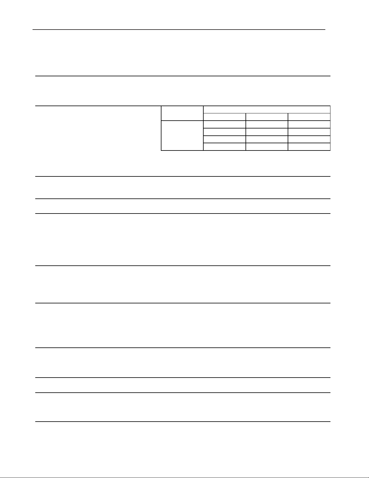
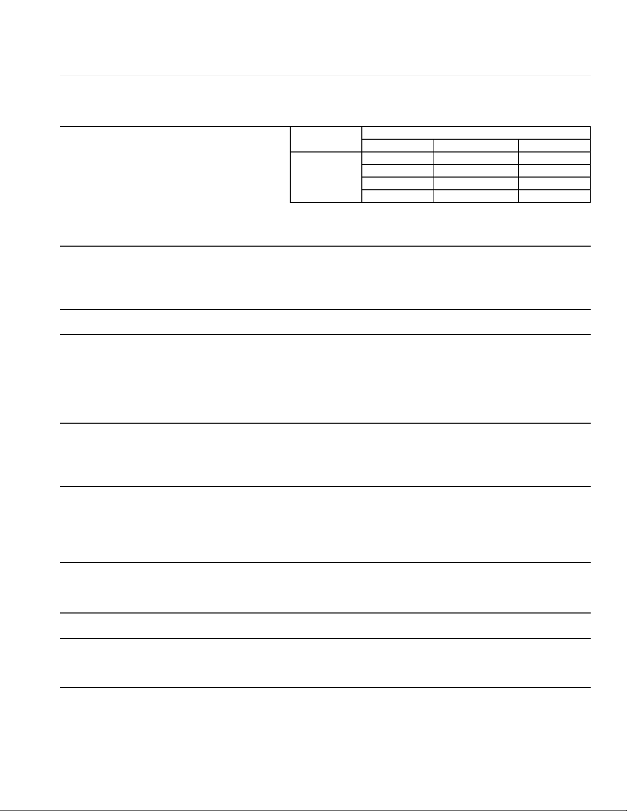
AC SUPPLY VOLTAGE 208-230/60/1 (3 wire with neutral 115V)
AMPERAGE 14.4 A ( 5 Min. Freeze AT 104°F / WT 80°F)
MINIMUM CIRCUIT AMPACITY 30 A
MAXIMUM FUSE SIZE 30 A
APPROXIMATE ICE PRODUCTION Ambient WATER TEMP. (°F)
PER 24 HR. Temp.(°F) 50 70 90
lbs./day ( kg/day ) 70 *1867 (847) 1777 (806) 1638 (743)
Reference without *marks 80 1798 (816) 1659 (752) 1511 (685)
90 1777 (806) *1560 (708) 1413 (641)
100 1744 (791) 1526 (692) 1278 (580)
SHAPE OF ICE Crescent Cube
ICE PRODUCTION PER CYCLE 45.3 lbs. (20.5 kg) 2160pcs.
APPROXIMATE STORAGE CAPACITY N/A
ELECTRIC & WATER CONSUMPTION 90/70°F 70/50°F
ELECTRIC W (kWH/100 lbs.) 2670(4.1) 2480(3.2)
WATER gal./24HR (gal./100 lbs.) 293(18.8) 579(31.0)
CEC/CEE TIER LEVEL 3
ENERGY STAR YES
EXTERIOR DIMENSIONS (WxDxH) 48" x 27-3/8" x 36-7/16" (1219 x 695 x 925 mm)
EXTERIOR FINISH Stainless Steel, Galvanized Steel (Rear)
WEIGHT Net 390 lbs. (177 kg), Shipping 415 lbs. (188 kg)
CONNECTIONS - ELECTRIC Permanent - Connection
- WATER SUPPLY Inlet 1/2" FPT
- DRAIN Outlet 3/4" FPT
3/8" OD Tube
CUBE CONTROL SYSTEM Float Switch
HARVESTING CONTROL SYSTEM Hot Gas and Water, Thermistor and Timer
ICE MAKING WATER CONTROL Timer Controlled. Overflow Pipe
COOLING WATER CONTROL N/A
BIN CONTROL SYSTEM Thermostat
COMPRESSOR Hermetic, Model CS16K6E-PFV-237
CONDENSER Air-Cooled , Fin and tube type
EVAPORATOR Vertical type, Stainless Steel and Copper
REFRIGERANT CONTROL Thermostatic Expansion Valve
REFRIGERANT CHARGE R404A, 4 lb. 10.1 oz. (2100g)
DESIGN PRESSURE High 467PSIG, Low 230PSIG
P.C. BOARD CIRCUIT PROTECTION High Voltage Cut-out ( Internal )
COMPRESSOR PROTECTION Auto-reset Overload Protector ( Internal )
REFRIGERANT CIRCUIT PROTECTION Auto-reset High Pressure Control Switch
LOW WATER PROTECTION Float Switch
ACCESSORIES -SUPPLIED N/A
-REQUIRED Ice Storage Bin
OPERATING CONDITIONS VOLTAGE RANGE 187 - 253 V
AMBIENT TEMP. 45 -100° F
WATER SUPPLY TEMP. 45 - 90° F
WATER SUPPLY PRESSURE 10 - 113 PSIG
I. Specications
A. Icemaker
1. KM-1900SAH (air-cooled)
Note: We reserve the right to make changes in specications and design without prior
notice.
6
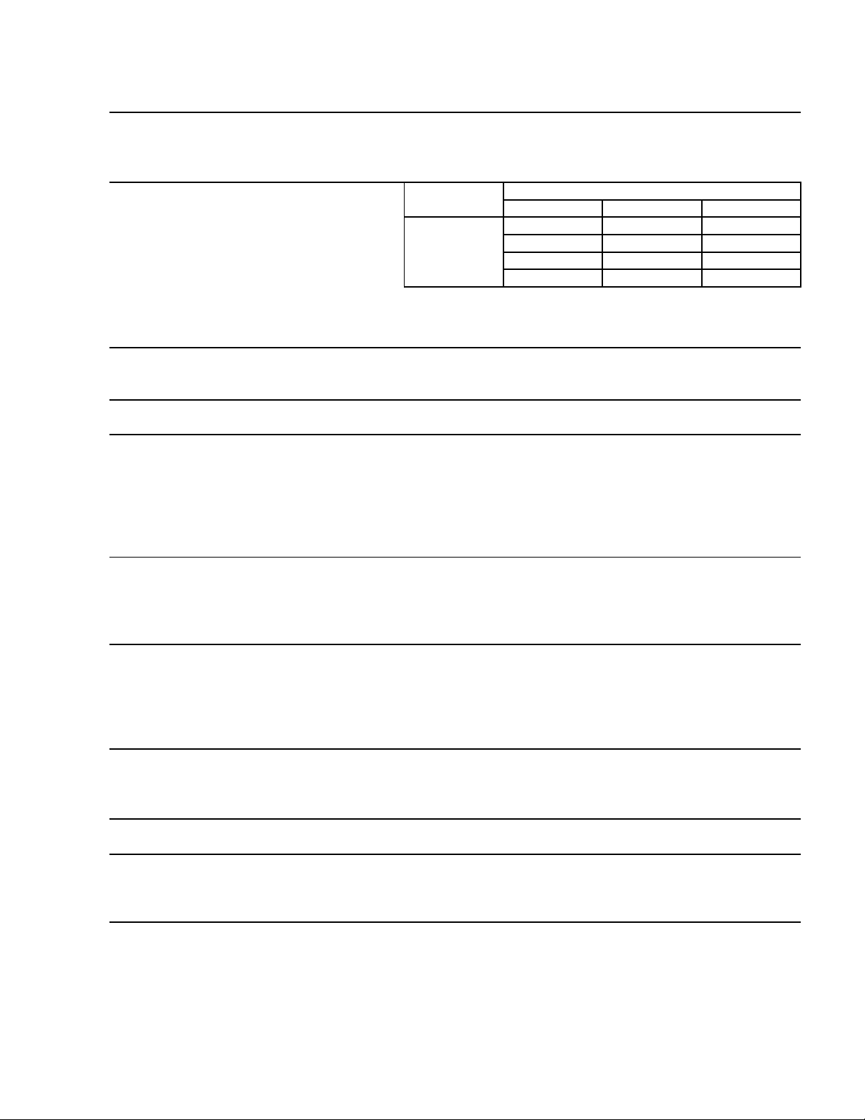
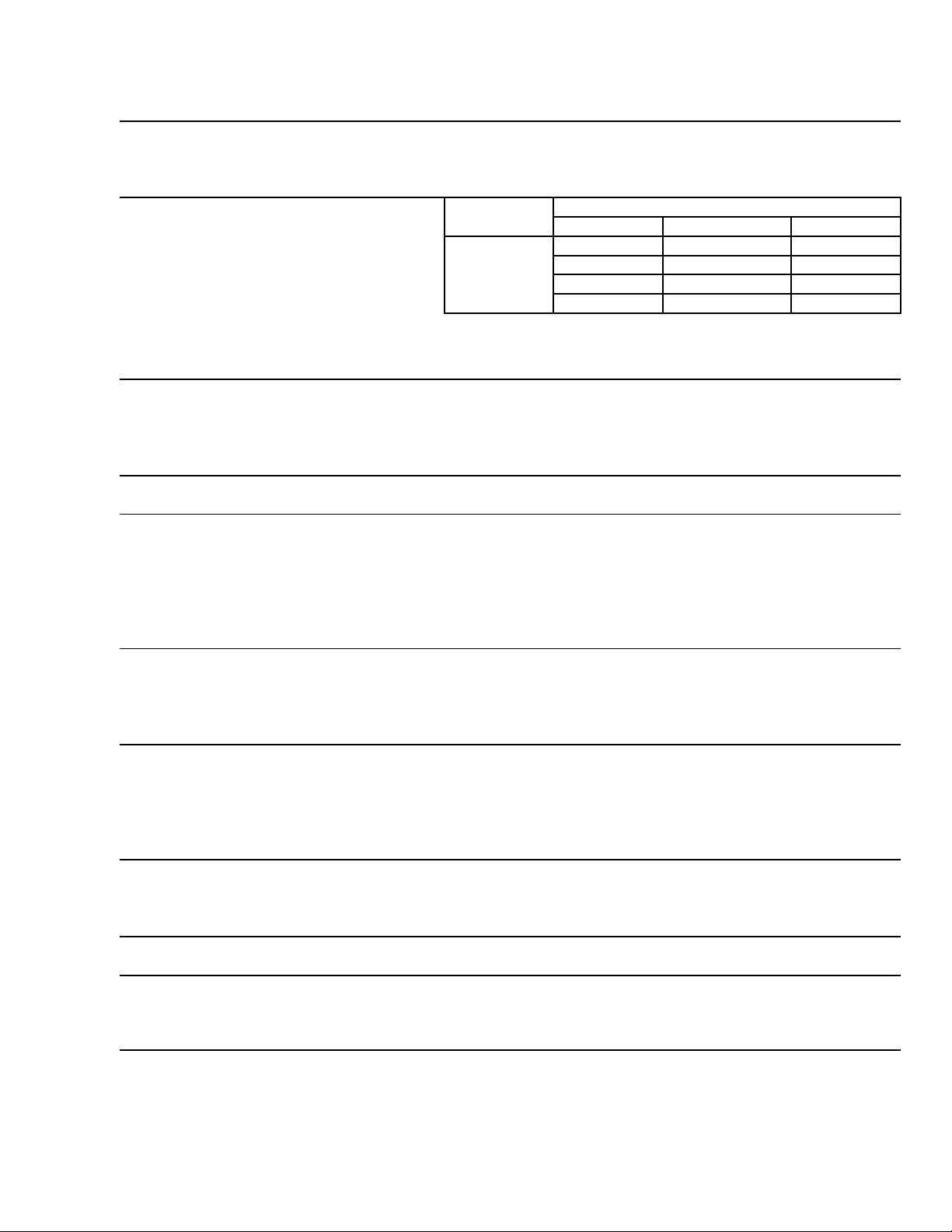
2. KM-1900SAH3 (air-cooled)
AC SUPPLY VOLTAGE 208-230/60/3
AMPERAGE 8.59 A ( 5 Min. Freeze AT 104°F / WT 80°F)
MINIMUM CIRCUIT AMPACITY 20 A
MAXIMUM FUSE SIZE 20 A
APPROXIMATE ICE PRODUCTION Ambient WATER TEMP. (°F)
PER 24 HR. Temp.(°F) 50 70 90
lbs./day ( kg/day ) 70 *1859 (843) 1763 (800) 1633 (741)
Reference without *marks 80 1786 (810) 1636 (742) 1507 (684)
90 1763 (800) *1530 (694) 1398 (634)
100 1738 (788) 1499 (680) 1277 (579)
SHAPE OF ICE Crescent Cube
ICE PRODUCTION PER CYCLE 45.5 lbs. (20.6 kg) 2160pcs.
APPROXIMATE STORAGE CAPACITY N/A
ELECTRIC & WATER CONSUMPTION 90/70°F 70/50°F
ELECTRIC W (kWH/100 lbs.) 2610(4.1) 2510(3.2)
WATER gal./24HR (gal./100 lbs.) 260(17.0) 548(29.5)
CEC/CEE TIER LEVEL 3
ENERGY STAR YES
EXTERIOR DIMENSIONS (WxDxH) 48" x 27-3/8" x 36-7/16" (1219 x 695 x 925 mm)
EXTERIOR FINISH Stainless Steel, Galvanized Steel (Rear)
WEIGHT Net 390 lbs. (177 kg), Shipping 415 lbs. (188 kg)
CONNECTIONS - ELECTRIC Permanent - Connection
- WATER SUPPLY Inlet 1/2" FPT
- DRAIN Outlet 3/4" FPT
3/8" OD Tube
CUBE CONTROL SYSTEM Float Switch
HARVESTING CONTROL SYSTEM Hot Gas and Water, Thermistor and Timer
ICE MAKING WATER CONTROL Timer Controlled. Overflow Pipe
COOLING WATER CONTROL N/A
BIN CONTROL SYSTEM Thermostat
COMPRESSOR Hermetic, Model CS16K6E-TF5-237
CONDENSER Air-Cooled , Fin and tube type
EVAPORATOR Vertical type, Stainless Steel and Copper
REFRIGERANT CONTROL Thermostatic Expansion Valve
REFRIGERANT CHARGE R404A, 4 lb. 10.1 oz. (2100g)
DESIGN PRESSURE High 467PSIG, Low 230PSIG
P.C. BOARD CIRCUIT PROTECTION High Voltage Cut-out ( Internal )
COMPRESSOR PROTECTION Auto-reset Overload Protector ( Internal )
REFRIGERANT CIRCUIT PROTECTION Auto-reset High Pressure Control Switch
LOW WATER PROTECTION Float Switch
ACCESSORIES -SUPPLIED N/A
-REQUIRED Ice Storage Bin
OPERATING CONDITIONS VOLTAGE RANGE 187 - 253 V
AMBIENT TEMP. 45 -100° F
WATER SUPPLY TEMP. 45 - 90° F
WATER SUPPLY PRESSURE 10 - 113 PSIG
Note: We reserve the right to make changes in specications and design without prior
notice.
7
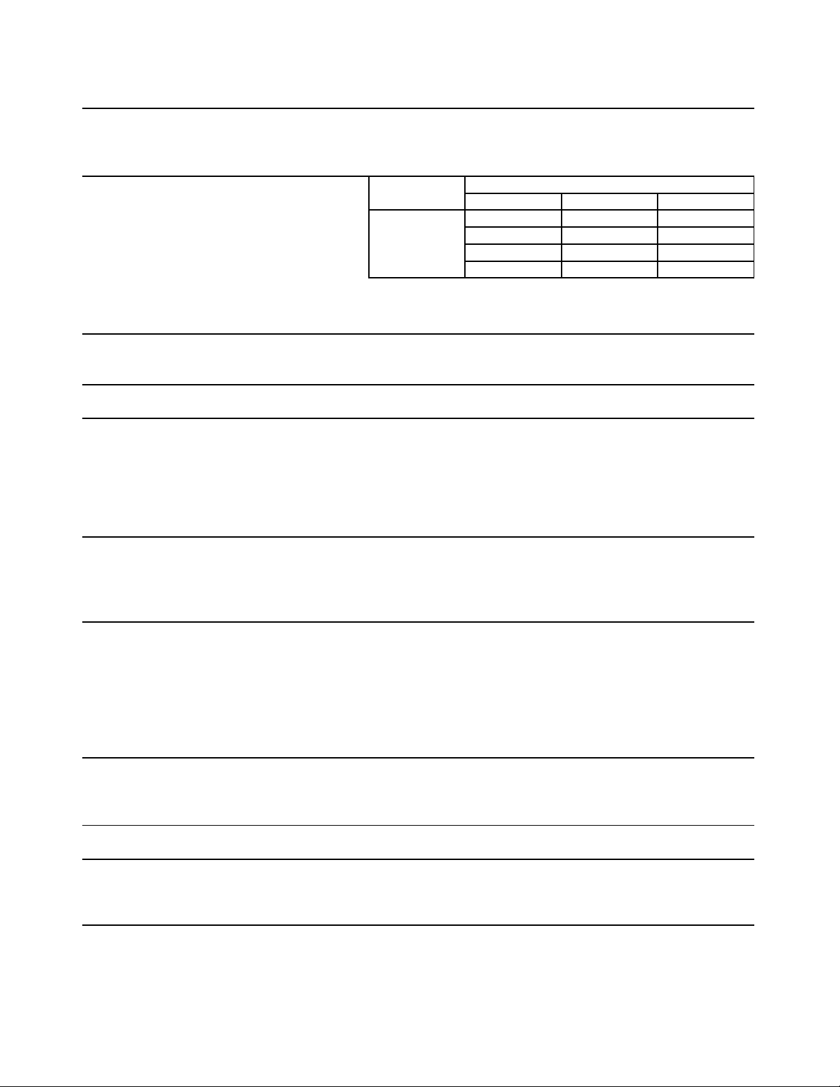
3. KM-1900SWH (water-cooled)
AC SUPPLY VOLTAGE 208-230/60/1 (3 wire with neutral 115V)
AMPERAGE 12.5 A ( 5 Min. Freeze AT 104°F / WT 80°F)
MINIMUM CIRCUIT AMPACITY 30 A
MAXIMUM FUSE SIZE 30 A
APPROXIMATE ICE PRODUCTION Ambient WATER TEMP. (°F)
PER 24 HR. Temp.(°F) 50 70 90
lbs./day ( kg/day ) 70 *1876 (851) 1868 (847) 1734 (787)
Reference without *marks 80 1870 (848) 1858 (843) 1655 (751)
90 1868 (847) *1850 (839) 1673 (759)
100 1800 (816) 1809 (820) 1511 (685)
SHAPE OF ICE Crescent Cube
ICE PRODUCTION PER CYCLE 47 lbs. (21.3 kg) 2160pcs.
APPROXIMATE STORAGE CAPACITY N/A
ELECTRIC & WATER CONSUMPTION 90/70°F 70/50°F
ELECTRIC W (kWH/100 lbs.) 2390(3.1) 2330(3.0)
POTABLE WATER gal./24HR (gal./100 lbs.) 348(18.8) 628(33.5)
WATER COOLED CONDENSER 1832(99) 1022(55)
gal./24HR (gal./100 lbs.)
CEC/CEE TIER LEVEL 3
ENERGY STAR N/A
EXTERIOR DIMENSIONS (WxDxH) 48" x 27-3/8" x 36-7/16" (1219 x 695 x 925 mm)
EXTERIOR FINISH Stainless Steel, Galvanized Steel (Rear)
WEIGHT Net 390 lbs. (177 kg), Shipping 415 lbs. (188 kg)
CONNECTIONS - ELECTRIC Permanent - Connection
- WATER SUPPLY Inlet 1/2" FPT Condenser Inlet 1/2" FPT
- DRAIN Outlet 3/4" FPT Condenser Outlet 1/2" FPT
3/8" OD Tube
CUBE CONTROL SYSTEM Float Switch
HARVESTING CONTROL SYSTEM Hot Gas and Water, Thermistor and Timer
ICE MAKING WATER CONTROL Timer Controlled. Overflow Pipe
COOLING WATER CONTROL N/A
BIN CONTROL SYSTEM Thermostat
COMPRESSOR Hermetic, Model CS16K6E-PFV-237
CONDENSER Water Cooled, Tube in Tube Type
EVAPORATOR Vertical type, Stainless Steel and Copper
REFRIGERANT CONTROL Thermostatic Expansion Valve
REFRIGERANT CHARGE R404A, 3 lb. 1.4 oz. (1400g)
DESIGN PRESSURE High 427PSIG, Low 230PSIG
P.C. BOARD CIRCUIT PROTECTION High Voltage Cut-out ( Internal )
COMPRESSOR PROTECTION Auto-reset Overload Protector ( Internal )
REFRIGERANT CIRCUIT PROTECTION Auto-reset High Pressure Control Switch
LOW WATER PROTECTION Float Switch
ACCESSORIES -SUPPLIED N/A
-REQUIRED Ice Storage Bin
OPERATING CONDITIONS VOLTAGE RANGE 187 - 253 V
AMBIENT TEMP. 45 -100° F
WATER SUPPLY TEMP. 45 - 90° F
WATER SUPPLY PRESSURE 10 - 113 PSIG
Note: We reserve the right to make changes in specications and design without prior
notice.
8
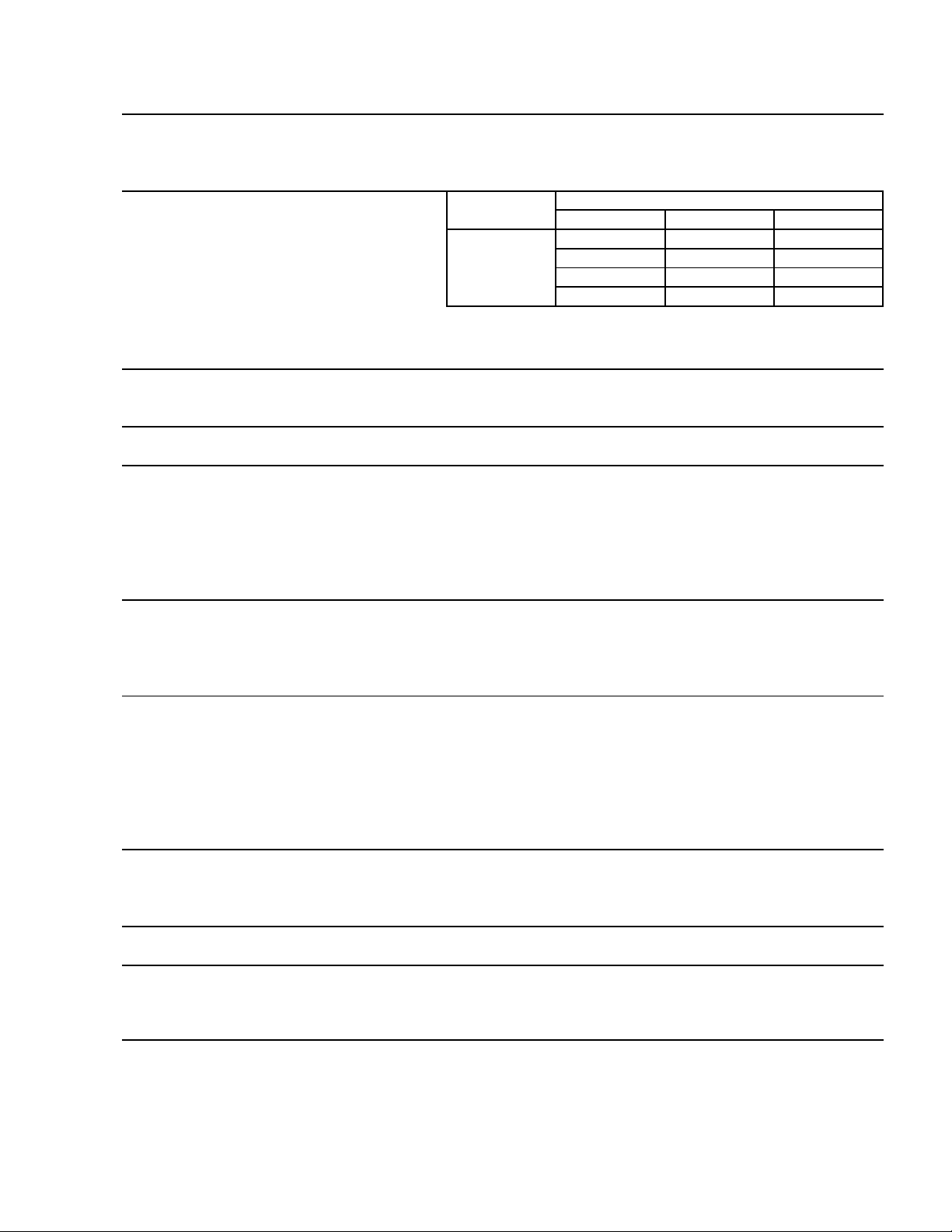
4. KM-1900SWH3 (water-cooled)
AC SUPPLY VOLTAGE 208-230/60/3
AMPERAGE 8.4 A ( 5 Min. Freeze AT 104°F / WT 80°F)
MINIMUM CIRCUIT AMPACITY 20 A
MAXIMUM FUSE SIZE 20 A
APPROXIMATE ICE PRODUCTION Ambient WATER TEMP. (°F)
PER 24 HR. Temp.(°F) 50 70 90
lbs./day ( kg/day ) 70 *1825 (828) 1822 (826) 1693 (768)
Reference without *marks 80 1823 (827) 1818 (824) 1619 (734)
90 1822 (826) *1814 (823) 1642 (745)
100 1754 (796) 1774 (805) 1484 (673)
SHAPE OF ICE Crescent Cube
ICE PRODUCTION PER CYCLE 45.4 lbs. (20.6 kg) 2160pcs.
APPROXIMATE STORAGE CAPACITY N/A
ELECTRIC & WATER CONSUMPTION 90/70°F 70/50°F
ELECTRIC W (kWH/100 lbs.) 2490(3.3) 2410(3.2)
POTABLE WATER gal./24HR (gal./100 lbs
.
341(18.8) 584(32.0)
WATER COOLED CONDENSER 1796(99) 982(54)
gal./24HR (gal./100 lbs.)
CEC/CEE TIER LEVEL 3
ENERGY STAR N/A
EXTERIOR DIMENSIONS (WxDxH) 48" x 27-3/8" x 36-7/16" (1219 x 695 x 925 mm)
EXTERIOR FINISH Stainless Steel, Galvanized Steel (Rear)
WEIGHT Net 390 lbs. (177 kg), Shipping 415 lbs. (188 kg)
CONNECTIONS - ELECTRIC Permanent - Connection
- WATER SUPPLY Inlet 1/2" FPT Condenser Inlet 1/2" FPT
- DRAIN Outlet 3/4" FPT Condenser Outlet 1/2" FPT
3/8" OD Tube
CUBE CONTROL SYSTEM Float Switch
HARVESTING CONTROL SYSTEM Hot Gas and Water, Thermistor and Timer
ICE MAKING WATER CONTROL Timer Controlled. Overflow Pipe
COOLING WATER CONTROL N/A
BIN CONTROL SYSTEM Thermostat
COMPRESSOR Hermetic, Model CS16K6E-TF5-237
CONDENSER Water Cooled, Tube in Tube Type
EVAPORATOR Vertical type, Stainless Steel and Copper
REFRIGERANT CONTROL Thermostatic Expansion Valve
REFRIGERANT CHARGE R404A, 3 lb. 1.4 oz. (1400g)
DESIGN PRESSURE High 427PSIG, Low 230PSIG
P.C. BOARD CIRCUIT PROTECTION High Voltage Cut-out ( Internal )
COMPRESSOR PROTECTION Auto-reset Overload Protector ( Internal )
REFRIGERANT CIRCUIT PROTECTION Auto-reset High Pressure Control Switch
LOW WATER PROTECTION Float Switch
ACCESSORIES -SUPPLIED N/A
-REQUIRED Ice Storage Bin
OPERATING CONDITIONS VOLTAGE RANGE 187 - 253 V
AMBIENT TEMP. 45 -100° F
WATER SUPPLY TEMP. 45 - 90° F
WATER SUPPLY PRESSURE 10 - 113 PSIG
Note: We reserve the right to make changes in specications and design without prior
notice.
9
5. KM-1900SRH (remote air-cooled)
AC SUPPLY VOLTAGE 208-230/60/1 (3 wire with neutral 115V)
AMPERAGE 14.9 A ( 5 Min. Freeze AT 104°F / WT 80°F)
MINIMUM CIRCUIT AMPACITY 30 A
MAXIMUM FUSE SIZE 30 A
APPROXIMATE ICE PRODUCTION Ambient WATER TEMP. (°F)
PER 24 HR. Temp.(°F) 50 70 90
lbs./day ( kg/day ) 70 *1915 (869) 1827 (829) 1676 (760)
Reference without *marks 80 1848 (838) 1712 (777) 1543 (700)
90 1827 (829) *1616 (733) 1451 (658)
100 1786 (810) 1577 (715) 1299 (589)
SHAPE OF ICE Crescent Cube
ICE PRODUCTION PER CYCLE 46.3 lbs. (21 kg) 2160pcs.
APPROXIMATE STORAGE CAPACITY N/A
ELECTRIC & WATER CONSUMPTION 90/70°F 70/50°F
ELECTRIC W (kWH/100 lbs.) 2630(3.9) 2460(3.1)
WATER gal./24HR (gal./100 lbs.) 323(20.0) 585(30.5)
CEC/CEE TIER LEVEL 3
ENERGY STAR YES
EXTERIOR DIMENSIONS (WxDxH) 48" x 27-3/8" x 36-7/16" (1219 x 695 x 925 mm)
EXTERIOR FINISH Stainless Steel, Galvanized Steel (Rear)
WEIGHT Net 390 lbs. (177 kg), Shipping 415 lbs. (188 kg)
CONNECTIONS - ELECTRIC Permanent - Connection
- WATER SUPPLY Inlet 1/2" FPT
- DRAIN Outlet 3/4" FPT
3/8" OD Tube
CUBE CONTROL SYSTEM Float Switch
HARVESTING CONTROL SYSTEM Hot Gas and Water, Thermistor and Timer
ICE MAKING WATER CONTROL Timer Controlled. Overflow Pipe
COOLING WATER CONTROL N/A
BIN CONTROL SYSTEM Thermostat
COMPRESSOR Hermetic, Model CS16K6E-PFV-279
CONDENSER Air-Cooled Remote, Condenser Unit URC-21F
EVAPORATOR Vertical type, Stainless Steel and Copper
REFRIGERANT CONTROL Thermostatic Expansion Valve
Condensing Pressure Regulator on URC-21F (190 PSI)
REFRIGERANT CHARGE R404A, 23 lb. 7.7 oz. (10650g)
(Icemaker 13 lbs. 12.5 oz. Cond. Unit 9 lbs. 11.2 oz.)
DESIGN PRESSURE High 467PSIG, Low 230PSIG
P.C. BOARD CIRCUIT PROTECTION High Voltage Cut-out ( Internal )
COMPRESSOR PROTECTION Auto-reset Overload Protector ( Internal )
REFRIGERANT CIRCUIT PROTECTION Auto-reset High Pressure Control Switch
LOW WATER PROTECTION Float Switch
ACCESSORIES -SUPPLIED N/A
-REQUIRED Ice Storage Bin, Remote Condenser Unit
OPERATING CONDITIONS VOLTAGE RANGE 187 - 253 V
AMBIENT TEMP. 45 -100° F
WATER SUPPLY TEMP. 45 - 90° F
WATER SUPPLY PRESSURE 10 - 113 PSIG
Note: We reserve the right to make changes in specications and design without prior
notice.
10
6. KM-1900SRH3 (remote air-cooled)
AC SUPPLY VOLTAGE 208-230/60/3
AMPERAGE 11.0 A ( 5 Min. Freeze AT 104°F / WT 80°F)
MINIMUM CIRCUIT AMPACITY 20 A
MAXIMUM FUSE SIZE 20 A
APPROXIMATE ICE PRODUCTION Ambient WATER TEMP. (°F)
PER 24 HR. Temp.(°F) 50 70 90
lbs./day ( kg/day ) 70 *1965 (891) 1771 (804) 1846 (838)
Reference without *marks 80 1817 (824) 1516 (688) 1781 (808)
90 1771 (804) *1304 (591) 1490 (676)
100 1901 (862) 1347 (611) 1660 (753)
SHAPE OF ICE Crescent Cube
ICE PRODUCTION PER CYCLE 46.5 lbs. (21.1 kg) 2160pcs.
APPROXIMATE STORAGE CAPACITY N/A
ELECTRIC & WATER CONSUMPTION 90/70°F 70/50°F
ELECTRIC W (kWH/100 lbs.) 2230(4.1) 2680(3.3)
WATER gal./24HR (gal./100 lbs.) 261(20.0) 590(30.0)
CEC/CEE TIER LEVEL 3
ENERGY STAR YES
EXTERIOR DIMENSIONS (WxDxH) 48" x 27-3/8" x 36-7/16" (1219 x 695 x 925 mm)
EXTERIOR FINISH Stainless Steel, Galvanized Steel (Rear)
WEIGHT Net 390 lbs. (177 kg), Shipping 415 lbs. (188 kg)
CONNECTIONS - ELECTRIC Permanent - Connection
- WATER SUPPLY Inlet 1/2" FPT
- DRAIN Outlet 3/4" FPT
3/8" OD Tube
CUBE CONTROL SYSTEM Float Switch
HARVESTING CONTROL SYSTEM Hot Gas and Water, Thermistor and Timer
ICE MAKING WATER CONTROL Timer Controlled. Overflow Pipe
COOLING WATER CONTROL N/A
BIN CONTROL SYSTEM Thermostat
COMPRESSOR Hermetic, Model CS16K6E-TF5-279
CONDENSER Air-Cooled Remote, Condenser Unit URC-21F
EVAPORATOR Vertical type, Stainless Steel and Copper
REFRIGERANT CONTROL Thermostatic Expansion Valve
Condensing Pressure Regulator on URC-21F (190 PSI)
REFRIGERANT CHARGE R404A, 23 lb. 7.7 oz. (10650g)
(Icemaker 13 lbs. 12.5 oz. Cond. Unit 9 lbs. 11.2 oz.)
DESIGN PRESSURE High 467PSIG, Low 230PSIG
P.C. BOARD CIRCUIT PROTECTION High Voltage Cut-out ( Internal )
COMPRESSOR PROTECTION Auto-reset Overload Protector ( Internal )
REFRIGERANT CIRCUIT PROTECTION Auto-reset High Pressure Control Switch
LOW WATER PROTECTION Float Switch
ACCESSORIES -SUPPLIED N/A
-REQUIRED Ice Storage Bin, Remote Condenser Unit
OPERATING CONDITIONS VOLTAGE RANGE 187 - 253 V
AMBIENT TEMP. 45 -100° F
WATER SUPPLY TEMP. 45 - 90° F
WATER SUPPLY PRESSURE 10 - 113 PSIG
Note: We reserve the right to make changes in specications and design without prior
notice.
11
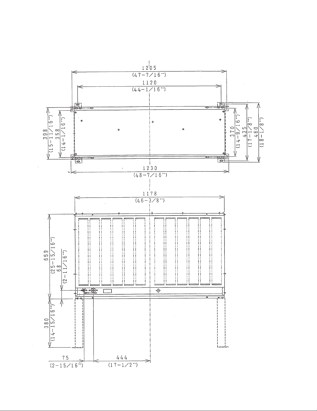
B. Condenser Unit
1. URC-21F
Unit: mm (in.)
1
SPECIFICATIONS
AC SUPPLY VOLTAGE 115/60/1 (Connection to Icemaker)
FAN MOTOR 115 V Total 2.6FLA 130W
EXTERIOR DIMENSIONS (WxDxH) 46-3/8" x 15-11/16" x 25-15/16" (1178 x 398 x 659 mm)
DIMENSIONS INCLUDING LEGS (WxDxH) 48-7/16" x 18-1/8" x 40-7/8" (1230 x 460 x 1039 mm)
EXTERIOR FINISH Galvanized Steel
WEIGHT Net 158 lbs. ( 72 kg ) Shipping 169 lbs. ( 77 kg )
CONNECTIONS - ELECTRIC Permanent - Connection
- REFRIGERANT Discharge Line 1-1/16"-12 UNF Fitting (#10 AEROQUIP)
Liquid Line 5/8"-18 UNF Fitting (#6 AEROQUIP)
CONDENSER Air-cooled, Fin and tube type
FAN MOTOR PROTECTION Thermal Protection
REFRIGERANT CONTROL Condensing Pressure Regulator
REFRIGERANT CHARGE R-404A 9 lb. 11oz. (4400g)
DESIGN PRESSURE High 467 PSIG 32.2 Bar
OPERATING CONDITIONS VOLTAGE RANGE 104 ~ 127 V
AMBIENT TEMP. -20 ~ 122 °F
ACCESSORIES -SUPPLIED Leg 2 pcs
Hex. Head Bolt w/Washer 8 x 16 8 pcs
Hex. Nut 8 8 pcs
MODEL: URC-1F
13
II. General Information
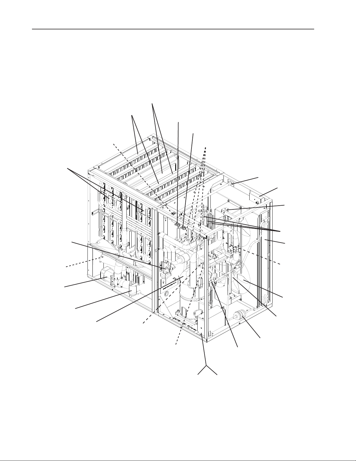
A. Construction
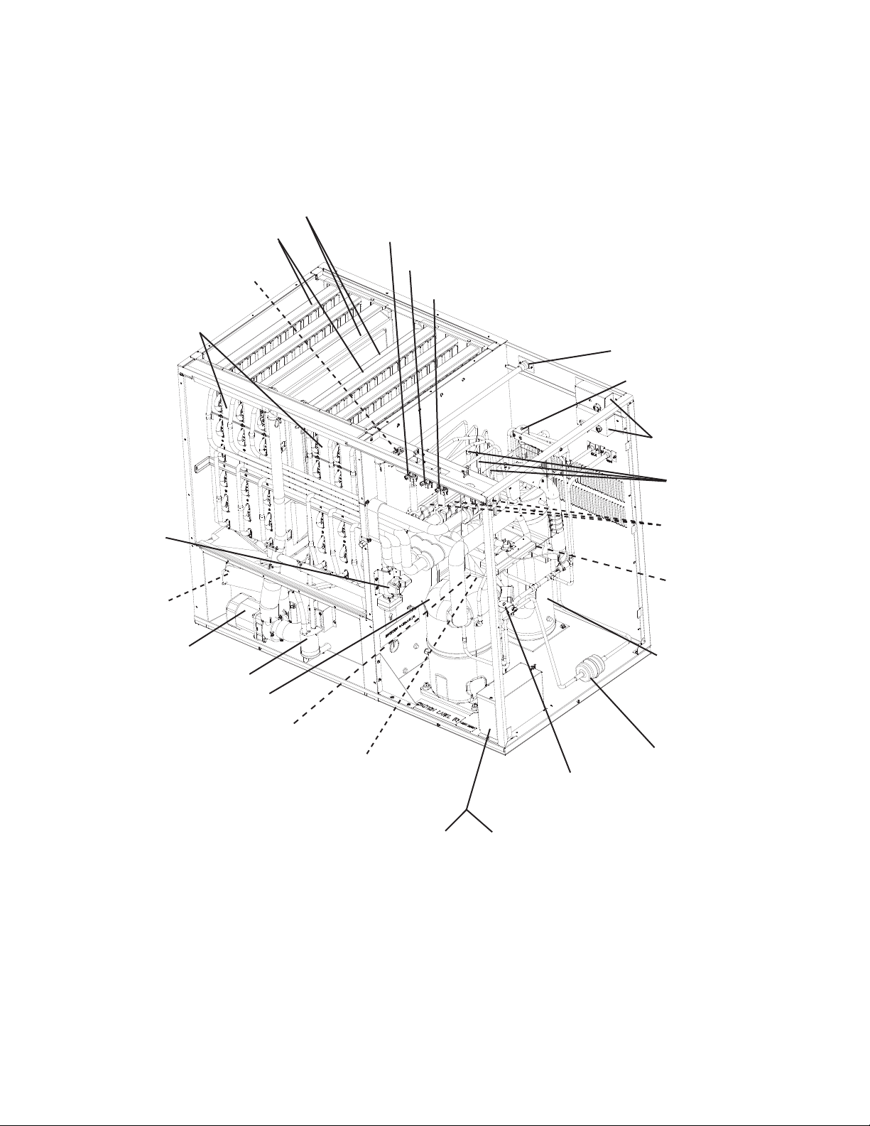
1. KM-1900SAH, KM-1900SAH3 (air-cooled)
Separators
Spray Tubes
Low-Side Service Valve
High-Side Service Valve
Evaporator Assembly
Cleaning Valve
Check Valve
(water)
Water Pump
Float Switch
Inlet Water Valve
Expansion Valves
Water Supply Inlet
Junction Box
Hot Gas Valve
Check Valves
Condenser
Control Box
Fan Blade
Compressor
Bin Control Thermostat
Control Switch
Capacitor Box
(KM-1900SAH)
14
Fan Motor
Drier
Liquid Line Valve
Transformer Box
(KM-1900SAH3)
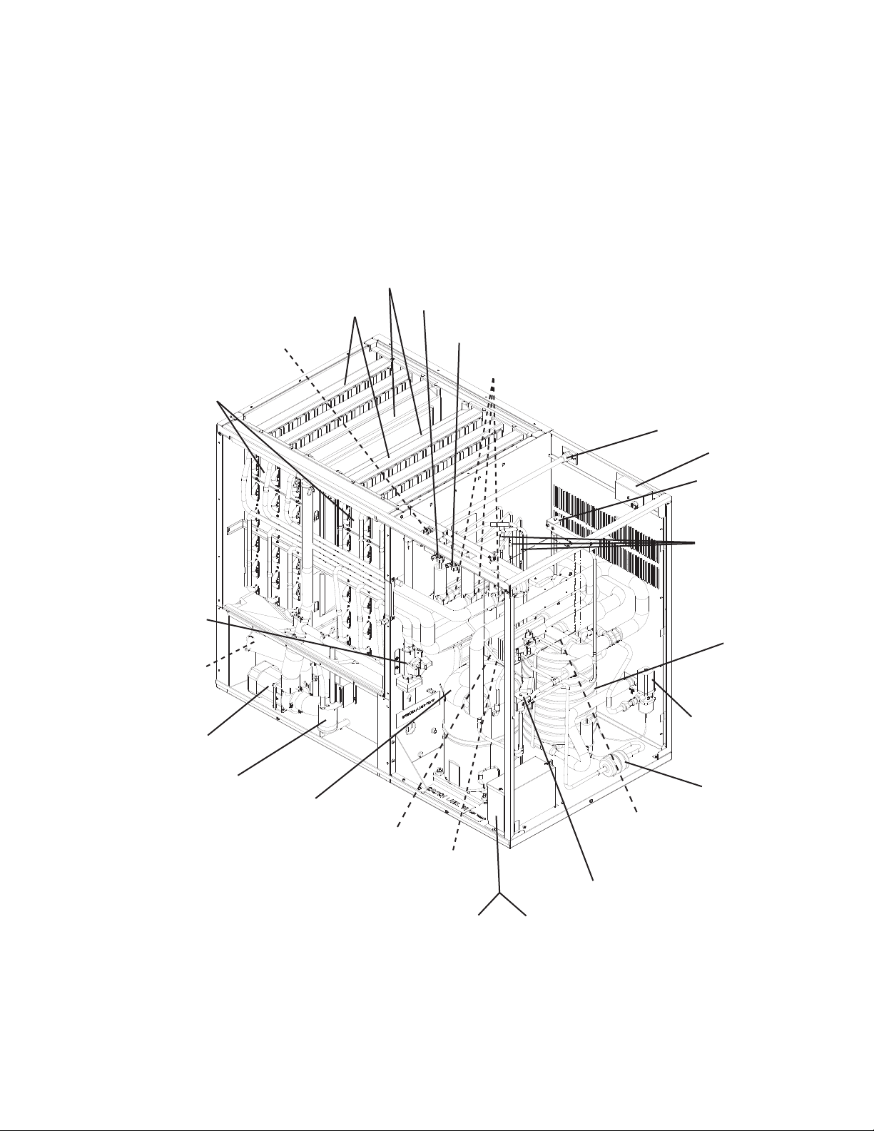
2. KM-1900SWH, KM-1900SWH3 (water-cooled)
Separators
Spray Tubes
Inlet Water Valve
Evaporator Assembly
Low-Side Service Valve
High-Side Service Valve
Expansion Valves
Water Supply Inlet
Junction Box
Hot Gas Valve
Cleaning Valve
Check Valve
(water)
Water Pump
Float Switch
Compressor
Bin Control Thermostat
Control Switch
Capacitor Box
(KM-1900SWH)
Check Valves
Condenser
Water Regulating
Valve
Drier
Control Box
Liquid Line Valve
Transformer Box
(KM-1900SWH3)
15
3. KM-1900SRH, KM-1900SRH3 (remote air-cooled)
Separators
Spray Tubes
Inlet Water Valve
Evaporator Assembly
Low-Side Service Valve
High-Side Service Valve
High-Side Liquid Service Valve
Water Supply Inlet
Hot Gas Valve
Junction Boxes
Check Valves
Cleaning Valve
Check Valve
(water)
Water Pump
Bin Control Thermostat
Float Switch
Compressor
Control Switch
Capacitor Box
(KM-1900SRH)
Expansion Valves
Control Box
Receiver Tank
Drier
Liquid Line Valve
Transformer Box
(KM-1900SRH3)
16

B. Sequence of Operation
The steps in the sequence are as outlined below. When power is supplied, the red
"POWER OK" LED on the control board comes on. A 5-second delay occurs at startup.
Note that the order of the LEDs from the outer edge of the board is 1, 4, 3, .
1. One Minute Fill Cycle
LED 4 is on. WV opens and the ll period begins. After 1 minute, the control board
checks for a closed F/S. If F/S is closed, the harvest cycle begins. If not, WV will remain
energized through additional 1 minute cycles until water enters the sump and F/S closes.
This serves as a low water safety to protect the PM.
2. Initial Harvest Cycle
LEDs 1, 4, and are on. WV remains open, Comp, FMR, and HGV opens. The control
board monitors the warming of the evaporator via the thermistor located on the suction
line. When the thermistor reaches 48°F (9°C), the control board reads a 3.9 kΩ signal
from the thermistor and turns harvest termination over to the adjustable harvest timer
(S4 dip switch 1 & ) which is factory set for normal conditions. The harvest timer has
settings of 60, 90, 10, and 180 seconds. For details, see "II.C.3.b) Harvest Timer (S4
dip switch 1 & )." When the harvest timer completes its countdown, the harvest cycle
is complete and the freeze cycle starts. The minimum total time allowed by the control
board for a complete harvest cycle is minutes. WV is energized during harvest for
a maximum of 6 minutes or the length of harvest, whichever is shorter. At the end of
harvest, the control board checks the position of F/S and proceeds to the freeze cycle if
it is closed or calls for a 1-minute ll if it is open.
3. Freeze Cycle
LED 1 is on. Comp and FMR continue to run, PM and FMS energize, and LLV opens,
HGV and WV close and the freeze cycle starts. For the rst 5 minutes the control board
will not accept a signal from F/S. This 5 minute minimum freeze acts as a short cycle
protection. At the end of 5 minutes, F/S assumes control. As ice builds on the evaporator
the water level in the sump lowers. The freeze continues until F/S opens and terminates
ice production.
4. Pump-Out Cycle
LEDs 1, 3, and are on. Comp and FMR continue to run, HGV opens, LLV closes,
and FMS de-energizes. PM stops for seconds. The pump motor then re-starts in the
reverse direction, taking water from the bottom of the sump and forcing pressure against
the check valve seat allowing water to go through the check valve and down the drain.
At the same time, water ows through the small tube to power ush the F/S. When the
pump-out timer (S4 dip switch 3 & 4) stops counting, the pump out is complete. The
1st pump out occurs after the 1st freeze cycle and every 10th cycle thereafter. The
pump-out frequency control (S4 dip switch 5 & 6) is factory-adjusted to drain the water
tank every 10 cycles, and no adjustment is required. However, where water quality is
bad and the icemaker needs a pump out more often, the pump-out frequency can be
adjusted. The pump-out frequency control (S4 dip switch 5 & 6) can be set to have
a pump out occur every cycle, or every , 5, or 10 cycles, see "II.C.3.d) Pump-Out
Frequency Control (S4 dip switch 5 & 6)."
17

5. Normal Harvest Cycle
LEDs 1, 4, and are on. Comp and FMR remain energized. FMS de-energizes and
the HGV and WV open. As the evaporator warms, the thermistor reaches 48°F (9°C).
The control board then receives the thermistor's 3.9 kΩ signal and starts the harvest
timer. When the harvest timer completes its countdown, the harvest cycle is complete.
The minimum total time allowed by the control board for a complete harvest cycle is
minutes. WV is open during harvest for a maximum of 6 minutes or the length of harvest,
whichever is shorter. At the end of harvest, the control board checks the position of the
F/S and proceeds to the freeze cycle if it is closed or calls for a 1-minute ll if it is open.
The unit continues to cycle through this sequence until the bin control senses ice and
shuts the unit down.
Legend: Comp–compressor; FMR–remote fan motors; FMS–self-contained fan motors;
F/S–oat switch; HGV–hot gas valve; LLV–liquid line valve; PM–pump motor;
WV–inlet water valve
18
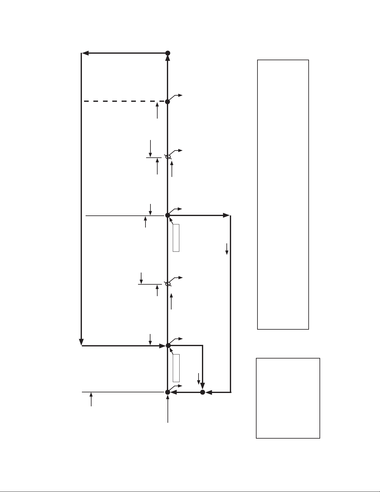
6. Sequence Flow Chart
Cycle
4. Pump-Out
• Minimum freeze time: 5 minutes
• Maximum freeze time: freeze timer setting
F/S in
control
5 minute timer
in control
F/S closed
PM stops for sec.,
then reverses for 10/0 sec.
each 1, , 5, or 10 cycles.
Comp continues
FMR continues
Freeze cycle
operation turned
over to F/S
Comp continues
FMR continues
HGV de-energized
WV de-energized
PM energized
HGV energized
FMS de-energized
LLV de-energized
FMS energized
LLV energized
F/S check
1 to 3 minute timer
in control
Thermistor in
2. Harvest Cycle 3. Freeze Cycle
• Maximum inlet water valve time: 6 minutes
• Maximum harvest time: 0 minutes
Fill Cycle
control
F/S closed
F/S check
1. One-Minute
Thermistor temp
reaches 48°F (9°C)
(3.9 kΩ or less)
Harvest timer starts
Comp energized
HGV energized
FMR energized
WV continues
LLV de-energized
F/S open
WV energized
F/S open
Components Energized when the Control Switch is in the "WASH" Position
The "WASH" position on the control switch is used when cleaning and sanitizing the unit. When in the
"WASH" position, power is supplied to the pump motor. With the cleaning valve closed, the cleaner and
sanitizer ow over the outside of the evaporator plate assembly. With the cleaning valve open, the cleaner
and sanitizer ow over both the outside and the inside of the evaporator plate assembly.
Note: Close the cleaning valve after cleaning and sanitizing are complete, otherwise the unit will not re-start
when the control switch is placed in the "ICE" position.
If F/S is open, compressor stops and cycle returns to 1-minute ll
Cycle Steps
KM-1900SAH/3, KM-1900SWH/3, KM-1900SRH/3 Sequence Flow Chart and Component Operation
Initial startup always
begins here
19
Legend:
Comp-compressor
FMR-remote fan motors
FMS-self-contained fan motors
F/S-oat switch
HGV-hot gas valve
LLV-liquid line valve
PM-pump motor
WV-inlet water valve
C. Control Board
• A Hoshizaki exclusive solid-state control is employed in KM-1900SAH/3,
KM-1900SWH/3, and KM-1900SRH/3 Stackable Crescent Cubers.
• All models are pretested and factory-adjusted.
CAUTION
1. Fragile, handle very carefully.
. The control board contains integrated circuits, which are susceptible to
failure due to static discharge. It is especially important to touch the metal
part of the unit before handling or replacing the board.
3. Do not touch the electronic devices on the board or the back of the board to
prevent damage to the board.
4. Do not change wiring and connections. Do not misconnect K3, K4, and K5,
because the same connector is used for the thermistor and oat switch. K4
is not connected.
5. Always replace the whole board assembly if it goes bad.
6. Do not short out power supply to test for voltage.
0
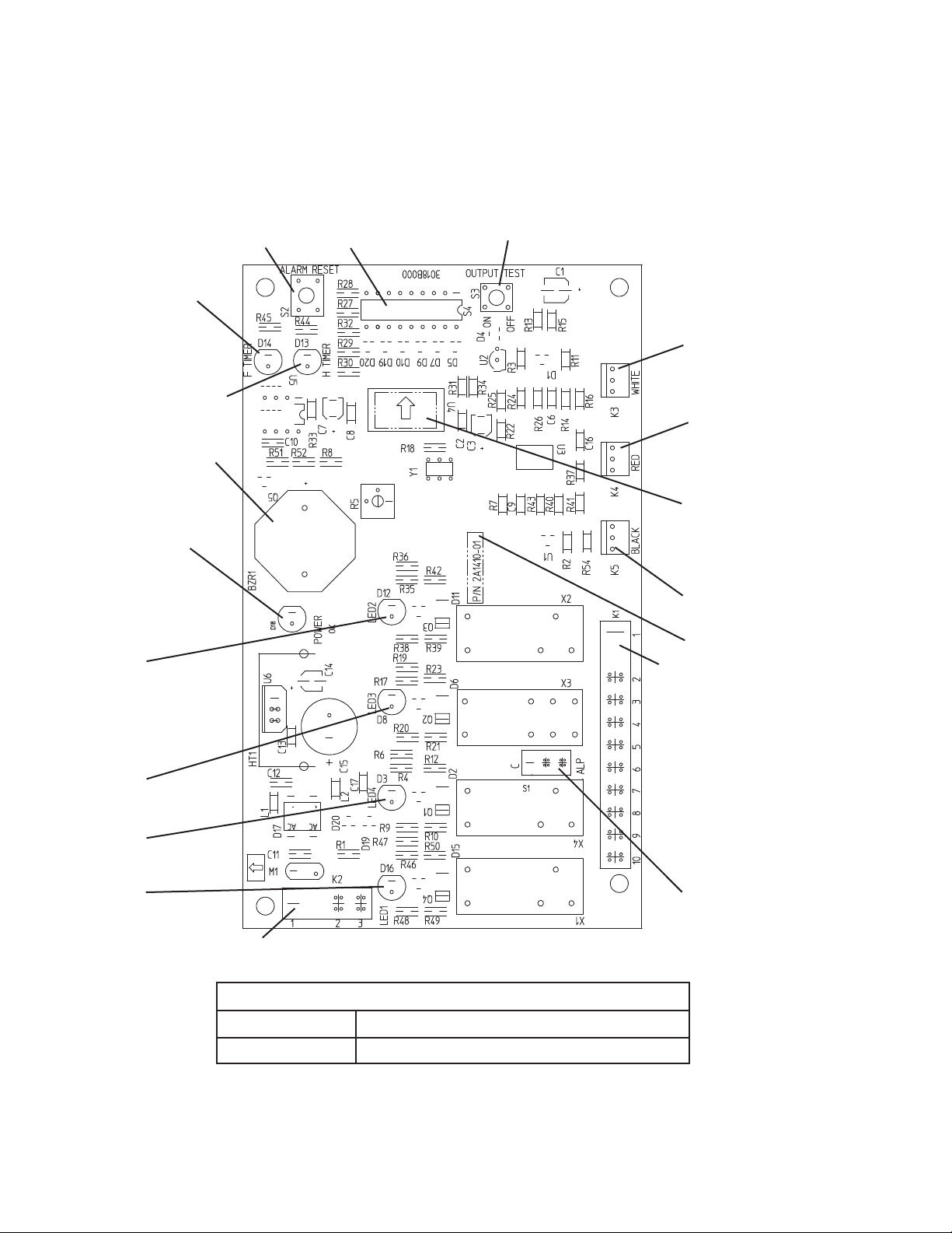
1. Control Board Layout
Control Products "E" Control Board
"ALARM RESET" Button
Backup Freeze
Timer LED
Backup Harvest
Timer LED
Alarm Buzzer
S4 Dip Switch
"OUTPUT TEST" Button
(used to test relays on board)
Connector K3
Harvest Control
(thermistor)
Connector K4
Open
(not connected)
Power LED
(lights when
power is supplied
to the board)
Relay LEDs (4)
(indicate which
relays are energized
as listed below)
LED
Hot Gas Valve
(HGV)
Self-Contained Fan
Motors (FMS) (FMS
off when LED on)
LED 3
Pump Motor (PM)
(on at pump out only)
LED 4
Inlet Water
Valve (WV)
LED 1
Compressor (Comp)
Remote Fan Motors
(FMR)
Transformer
Connector
Microprocessor
(board revision level
indicated by last
digits on label)
Connector K5
Float Switch
Part Number
Connector K1
Pins #1 through #10
#1, 9 Magnetic Contactor
# Hot Gas Valve
#3 Liquid Line Valve
Self-Contained Fan Motors
(FMS)
#4 Pump Motor (icemaking)
#5 Pump Motor (pump out)
#6 Inlet Water Valve
#7, 10 Power Supply
#8 Open
Switch for "C" board
and "ALPINE" board
(service boards only)
Control Board
Part Number 2A1410-01 (factory); 2A1410-02 (service)
Type HOS-001A (Control Products - 10 Pin)
1
 Loading...