

Page 1
Hoshizaki America, Inc.
Hoshizaki
Stackable Crescent Cuber
Models
KM-1301SAH-E
“A Superior Degree
of Reliability”
www.hoshizaki.com
KM-1301SWH-E
KM-1301SRH-E
PARTS LIST
89/336
73/23
Number: 71348
Issued: 11-29-2012
Revised: 9-14-2015
Page 2

CONTENTS
Auxiliary Codes ...................................................................................................................... 3
Note About Ordering Parts .................................................................................................... 3
A. Main Assembly & Refrigeration Circuit .............................................................................. 4
KM-1301SAH-E ................................................................................................................. 4
KM-1301SWH-E ................................................................................................................ 7
KM-1301SRH-E ................................................................................................................. 9
B. Water Circuit .....................................................................................................................11
C. Control Box Assembly ..................................................................................................... 14
D. Accessories & Labels ...................................................................................................... 16
2
Page 3

Auxiliary Codes
KM-1301SAH-E
T-0 December 2008
U-0 February 2009
U-1 September 2009
V-0 January 2010
V-1 June 2010
V-2 July 2010
A-0 January 2011
A-1 October 2011
B-0 January 2012
C-0 January 2013
D-0 January 2014
E-0 January 2015
E-1 August 2015
KM-1301SWH-E
V-0 September 2010
A-0 January 2011
A-1 October 2011
C-1 March 2013
D-0 June 2014
E-0 May 2015
KM-1301SRH-E
V-0 September 2010
A-0 January 2011
B-0 August 2012
C-0 January 2013
D-0 January 2014
D-1 August 2014
E-0 January 2015
Auxiliary Code Breakdown
The auxiliary code is the rst two characters in the serial number. The rst character
indicates the year. Years progress or regress in alphabetical order. The series runs from
"A" through "V" and the letters "I" and "O" are skipped. The second character indicates
signicant part changes within a year. Base is "0" and this number advances for each
change.
Note About Ordering Parts
Most assemblies cannot be ordered as complete units; parts in the assemblies generally
must be ordered separately.
IMPORTANT
IEC standards require that the clamping means of earthing terminals be
adequately secured against accidental loosening and that accessible metal parts
of the icemaker which may become live in the event of an insulation fault be
permanently and reliably connected to an earthing terminal within the icemaker or
to the earthing contact of the icemaker inlet. This is accomplished in this icemaker
through the use of stainless steel lock washers.
3
Page 4
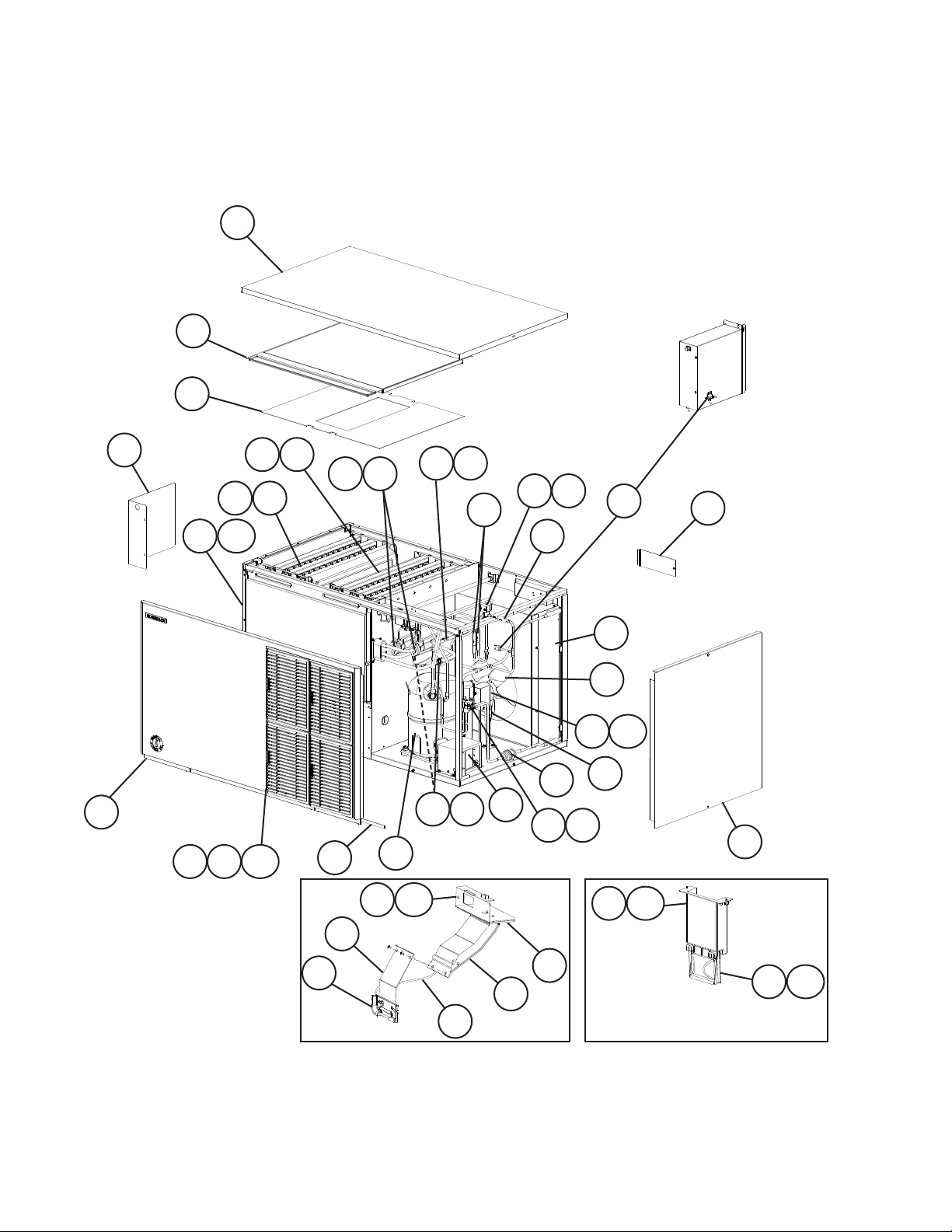
A. Main Assembly & Refrigeration Circuit
KM-1301SAH-E
T-0 to E-1
5
9
10
7
8
24 25
23 25
8a
26 27
35 36
33
30 32
40
V-1 and Later
34
T-0 to V-0
11
22
39
37a
37
41
1
28 29
18
38
31 32
6
14
21
14a
20
20a
4a
43
2
12
17
15
13
16
T-0 to E-0 E-1 and Later
4
19
19a
Page 5
Title: A. Main Assembly & Refrigeration Circuit Model: KM-1301SAH-E
T- 0
V-1
A-1
Index
No. Description
1 Front Panel 2A2224-02 1 1 1 1
2 Gasket L=1219 mm 4A0808L02 1 1 1 1
3 Air Filter 2A2063G01 4 4 4 4
4 Louver 1A0548-01 4 4 4 4
4a Push Retainer 4A2414-01 12 12 12 12
5 Top Panel 2A2255-01 1 1 1 1
6 Right Side Panel 2A2226G01 1 1 1 1
7 Control Box Cover 3A2386-01 1 1 1 1
8 Front Insulation 324215G01 1 1 1 1
8a Thumbscrew 415949G12 1 1 1 1
9 Top Insulation 324216G01 1 1 1 1
10 Spacer 324321-01 1 1 1 1
11 Junction Box Cover 4A1767-01 1 1 1 1
12 Bin Control Bulb Holder 3A3903-01 1 1 1 13 Bin Control Bulb Holder C 216340G01 1 1 1 14 Bin Control Bulb Holder D 328742-01 1 1 1 -
14a Thumbscrew 415949G12 2 2 2 -
15 Spacer 439727-01 1 1 1 16 Silicone Hose L=285 mm 7730I3812 1 1 1 17 Bin Control Extension Bracket 3A0408-01 1 1 1 18 Main Transformer 4A5262-01 1 1 1 1
19 Mechanical Bin Control 2A4393G01 1
19a Thumbscrew 415949G12 2
20 Bin Control Mounting Bracket 3A5726-01 1
20a Thumbscrew 415949G12 2
Material or
Model Number Part Number
Main Assembly
to
V-0
to
A-0
to
E-0 E-1
Required Number
Refrigeration Circuit
21 Compressor 4A1749-01 1 1 -
4A1749-03 1 1
22 Condenser 213621-01 1 1 1 1
23 Left Evaporator Bank HS-0208 2A0414G02 1 1 1 1
24 Right Evaporator Bank HS-0209 2A0415G02 1 1 1 1
25 Separator Hook 324152-01 8 8 8 8
26 Thermostatic Expansion Valve 4A1482-01 2 2 2 2
27 Thermostatic Expansion Valve
Cover
28 Thermostatic Expansion Valve
Bulb Holder
29 Clamp 443461-02 2 2 2 2
30 Hot Gas Valve Body 4A3978-01 1 1 1 1
31 Liquid Line Valve Body 4A3276-01 1 1 1 1
32 Valve Coil 4A3277-01 2 1 1 1
33 Check Valve 4A1373-01 2 2 2 2
34 High-Pressure Switch 433441-07 1 -
35 Thermistor L=1050 mm 429006-03 1 1 1 1
36 Thermistor Holder 427430-01 1 1 1 1
3A0944-01 2 2 2 2
3A0107-01 2 2 2 2
463180-04 1 1 1
5
Page 6

Title: A. Main Assembly & Refrigeration Circuit Model: KM-1301SAH-E
T- 0
V-1
A-1
Index
No. Description
37 Fan Motor 4A3158-01 1 1 1 1
37a Self-Locking Nut 8-32 7N21I0832 4 4 4 4
38 Fan Motor Capacitor 5MFD,
39 Fan Blade 4A3959-01 1 1 1 1
40 Strainer 441569-02 1 1 1 1
41 Drier 4A2666-01 1 1 1 1
Material or
Model Number Part Number
443192-02 1 1 1 1
250VAC
to
V-0
to
A-0
to
E-0 E-1
Required Number
6
Page 7

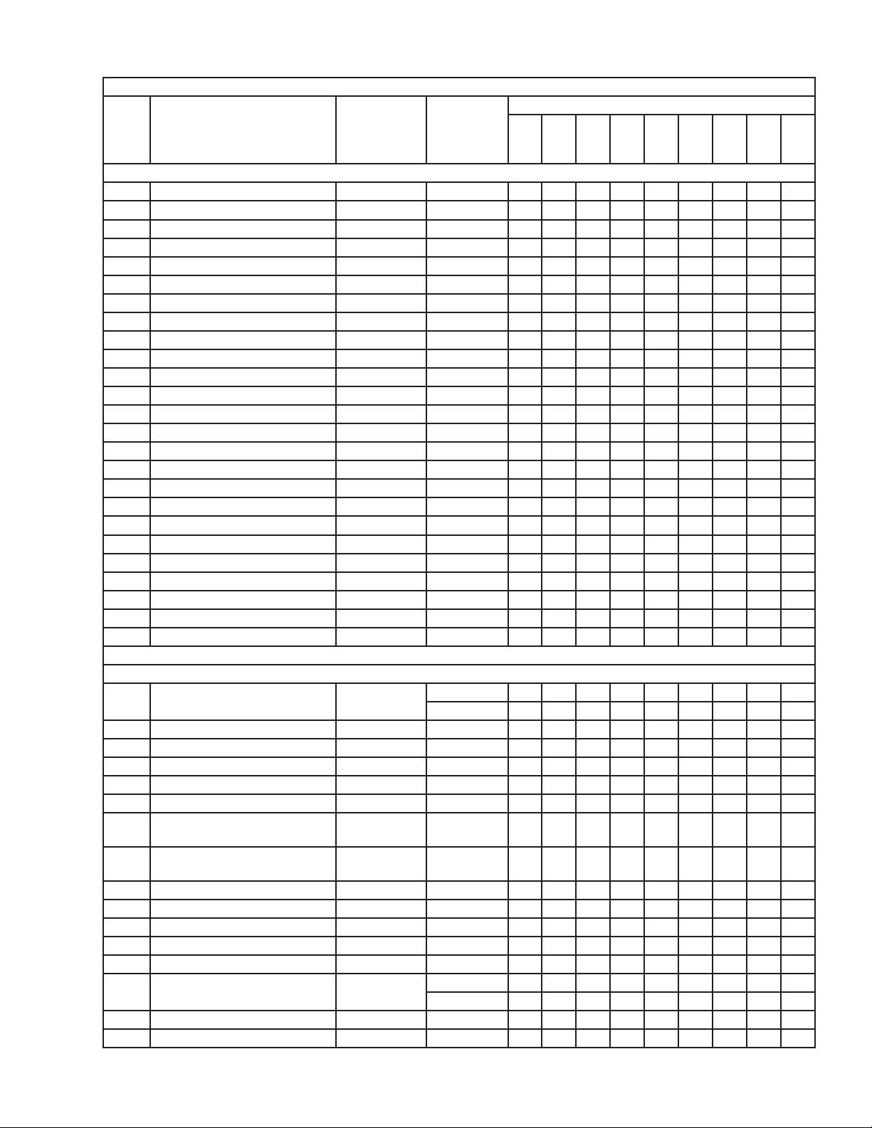
A. Main Assembly & Refrigeration Circuit
KM-1301SWH-E
V-0 to E-0
2
5
7
6
15
14
4a
4
1
16 17
18 19
10
25 26
20 22
12
27
23
24
21 22
13
28
11
3
9a
9
8a
8
7
Page 8

Title: A. Main Assembly & Refrigeration Circuit Model: KM-1301SWH-E
A-1
Index
No. Description
1 Front Panel 2A2224-01 1 1 1
2 Top Panel 2A2255-01 1 1 1
3 Right Side Panel 2A2226G01 1 1 1
4 Front Insulation 324215G01 1 1 1
4a Thumbscrew 415949G12 1 1 1
5 Top Insulation 324216G01 1 1 1
6 Spacer 324321-01 1 1 1
7 Control Box Cover 3A2386-01 1 1 1
8 Mechanical Bin Control 2A4393G01 1 1 1
8a Thumbscrew 415949G12 2 2 2
9 Bin Control Mounting Bracket 3A5726-01 1 1 1
9a Thumbscrew 415949G12 2 2 2
10 Main Transformer 4A5262-01 1 1 1
11 Compressor 4A1749-01 1 -
12 Condenser HS-0163 2A2359G04 1 1 -
13 Water Regulating Valve 4A0911-07 1 1 1
14 Left Evaporator Bank HS-0208 2A0414G02 1 1 1
15 Right Evaporator Bank HS-0209 2A0415G02 1 1 1
16 Thermostatic Expansion Valve 4A1482-01 2 2 2
17 Thermostatic Expansion Valve
Cover
18 Thermostatic Expansion Valve
Bulb Holder
19 Clamp 443461-02 2 2 2
20 Hot Gas Valve Body 4A3978-01 1 1 1
21 Liquid Line Valve Body 4A3276-01 1 1 1
22 Valve Coil 4A3277-01 2 2 2
23 Check Valve 4A1373-01 2 2 2
24 High-Pressure Switch 463180-05 1 1 1
25 Thermistor L=1050 mm 429006-03 1 1 1
26 Thermistor Holder 427430-01 1 1 1
27 Strainer 441569-02 1 1 1
28 Drier 4A2666-01 1 1 1
Material or
Model Number Part Number
Main Assembly
Refrigeration Circuit
4A1749-03 1 1
3A7236-01 1
3A0944-01 2 2 2
3A0107-01 2 2 2
V-0
A-0
to
C-0
Required Number
C-1
to
E-0
8
Page 9

A. Main Assembly & Refrigeration Circuit
KM-1301SRH-E
V-0 to E-0
2
5
7
4
4a
6
14
15
1
18 19
16 17
11 12
25
10
26
20 22
28
27
23
29
30
24
21 22
13
3
9a
9
8a
8
9
Page 10

Title: A. Main Assembly & Refrigeration Circuit Model: KM-1301SRH-E
Index
No. Description
1 Front Panel 2A2224-01 1 1
2 Top Panel 2A2255-01 1 1
3 Right Side Panel 2A2226G01 1 1
4 Front Insulation 324215G01 1 1
4a Thumbscrew 415949G12 1 1
5 Top Insulation 324216G01 1 1
6 Spacer 324321-01 1 1
7 Control Box Cover 3A2386-01 1 1
8 Mechanical Bin Control 2A4393G01 1 1
8a Thumbscrew 415949G12 2 2
9 Bin Control Mounting Bracket 3A5726-01 1 1
9a Thumbscrew 415949G12 2 2
10 Main Transformer 4A5262-01 1 1
11 Compressor
(B-0 and later utilize external
crankcase heater-item 12)
12 Crankcase Heater 4A5397-02 1
13 Receiver Tank 437652-01 1 1
14 Left Evaporator Bank HS-0208 2A0414G02 1 1
15 Right Evaporator Bank HS-0209 2A0415G02 1 1
16 Thermostatic Expansion Valve 4A1482-01 2 2
17 Thermostatic Expansion Valve
Cover
18 Thermostatic Expansion Valve
Bulb Holder
19 Clamp 443461-02 2 2
20 Hot Gas Valve Body 4A3978-01 1 1
21 Line Valve Body 4A3276-01 1 1
22 Valve Coil 4A3277-01 2 2
23 Check Valve 4A1373-01 2 2
24 High-Pressure Switch 463180-04 1 1
25 Thermistor L=1050 mm 429006-03 1 1
26 Thermistor Holder 427430-01 1 1
27 Strainer 441569-02 1 1
28 Drier 4A2666-01 1 1
29 Liquid Line Coupling 433751G01 1 1
30 Discharge Line Coupling 434136G01 1 1
Material or
Model Number Part Number
Main Assembly
Refrigeration Circuit
4A1749-02 1 4A1749-03 1
3A0944-01 2 2
3A0107-01 2 2
V-0
A-0
Required Number
B-0
to
E-0
10
Page 11

B. Water Circuit
KM-1301S_H-E
T-0 to E-1
16
18
29
14
25
27
13
17
26
15
28
35
36
31
30
34
37 38
20
12
11
19
10
21
22
24
Pump Motor Assembly
4
3a
9
6
5
7
7b
11
2
3d 3e
8
3
7a
3b 3c
33
1
23
32
Page 12

Title: B. Water Circuit Model: KM-1301S_H-E
T- 0
to
Index
No. Description
1 Pump Motor Assembly
(includes items 2 through 8)
2 Pump Motor 2U0106-01 1 1
3 Pump Motor Flange 215662-01 1 1
3a Tooth Washer 7R22-0600 2 2
3b Hex Bolt 6×40, SS 7B02-0640 4 4
3c Flat Washer 7W22-0600 4 4
3d Split Lock Washer 7L22-0600 4 4
3e Hex Nut 7N12-0600 4 4
4 Mechanical Seal 4A3820-01 1 1
5 Packing 428547-01 1 1
6 Impeller 334706G01 1 1
7 Pump Housing 213687-01 1 1
7a Hex Bolt 4×55, SS 7B02-0455 4 4
7b Hex Flange Nut 7J02-0400 4 4
8 Pin 4A0648-01 1 1
9 Pump Motor Bracket 323904-01 1 1
10 Water Supply Pipe 4A5216G04 1 1
11 Rubber Gasket 413854-03 1 1
12 Inlet Water Valve 4A5251-02 1 1
13 Distributor 438276G01 1 1
14 Distributor Hose A 325738-01 1 1
15 Distributor Hose B 325738-02 1 1
16 Distributor Hose C 323985-01 2 2
17 Joint Pipe 439297-01 1 1
18 Spray Tube 437049G01 6 6
19 Spray Guide 208586-01 18 18
20 Separator A 213622-01 2 2
21 Separator B 2A0100-01 2 2
22 Cube Guide 214243-01 2 2
23 Hose A 435091-01 1 1
24 Hose B 436599-01 1 1
25 Vinyl Hose L=420 mm 7716-2732 1 1
26 O-Ring 7611-G035 1 1
27 Drain Valve Spring 322110-01 1 1
28 Drain Valve Seat 433705-01 1 1
29 Drain Valve Housing 323613-01 1 1
30 Overow Cap 323978-01 1 1
31 Drain Valve O-Ring 7611-P018 1 32 Float Switch Connector 426799-04 1 1
33 Float Switch 4A3624-01 1 1
34 Silicone Hose L=140 mm 7730I3812 1 1
35 Silicone Hose L=390 mm 7730I3896 1 1
36 Drain Hose 324757-01 1 1
37 Drain Plug 309246-01 1 1
38 Drain Plug O-Ring 7611-P015 1 1
Material or
Model Number Part Number
S-0862 215692A04 1 1
E-0
(D)
Required Number
E-0
(E)
to
E-1
12
Page 13

Title: B. Water Circuit Model: KM-1301S_H-E
Index
No. Description
Hose Clamp 13.5 mm 427443-07 6 6
Hose Clamp 18 mm 427443-05 1 1
Hose Clamp 25 mm 427443-03 7 7
Hose Clamp 32 mm 427443-09 2 2
Material or
Model Number Part Number
Hose Clamps
T- 0
to
E-0
(D)
Required Number
E-0
(E)
to
E-1
13
Page 14

C. Control Box Assembly
KM-1301S_H-E
T-0 to E-1
KM-1301SAH-E
V-0 and Earlier
13
KM-1301SRH-E
V-0 to D-0
5
1a
1
98
12
Thermostat
Bin Control
4
Mechanical
7
X3 (T-0, U-0)
X2 (T-0, U-0)
X1 (T-0, U-0)
Bin Control
X11
(U-1 & Later)
X10
(U-1 & Later)
6
3
2
X1 (T-0, U-0) or X10 (U-1 and later) - Pump Direction Relay
X2 (T-0, U-0) or X 11 (U-1 and later) - Control Relay for X1 (T-0, U-0) or X10 (U-1 and later) Pump Direction Relay
X3 - Harvest Pump Timer Relay (Auxiliary Code T-0, U-0)
11
10
14
Page 15

Title: C. Control Box Assembly Model: KM-1301S_H-E
T- 0
V-1
D-1
Index
No. Description
Material or
Model Number Part Number
to
V-0
to
D-0
to
E-0 E-1
1 "G" Control Board 2A3792-01 1 1 1 1
1a Control Board Support 4A0336-03 4 4 4 4
2 Run Capacitor 35MFD,
3A2005-12 1 1 1 1
440VAC
3 Start Capacitor 160MFD,
4A1094-01 1 1 1 1
330VAC
4 Start Relay 4A1107-13 1 1 1 1
5 Pump Motor Capacitor 15.0MFD,
4A2128-02 1 1 1 1
250VAC
6 Relay
406132-07 3 2 2 2
(X1, X2, and X3 - T-0 and U-0)
(X10 and X11 - U-1 and later)
7 Control Transformer 3A0172-01 1 1 1 1
8 Fuse Holder 4A5443-01 1 1 1 1
9 Fuse AGC-10A,
4A0893-07 1 1 1 1
250VAC
10 Control Switch 4A2436-01 1 1 1 1
11 Bin Control Thermostat
12 K-4 Jumper
Bin Control Wire Harness
13 Magnetic Contactor
Compressor Relay
KM-1301SAH-E
KM-1301SAH-E
KM-1301SAH-E
KM-1301SWH-E
KM-1301SRH-E
KM-1301SAH-E
KM-1301SAH-E
KM-1301SWH-E
KM-1301SRH-E
4A2879-02 1 1 1 4A4883G01 1 1 1 4A5197G01 1
1 1 1
428393-01 1 4A3140-01 1 1 1
1 1 1 1
4A5096-01 1 1 4A3140-01 1 1
Required Number
15
Page 16

D. Accessories & Labels
KM-1301S_H-E
T-0 to E-1
1
3
2
Title: D. Accessories & Labels Model: KM-1301S_H-E
T- 0
to
Index
No. Description
1 Hoshizaki Emblem Label 4A0560-01 1 1
2 Penguin Label 4A0526-01 1 1
3 Air Filter Label
4 Universal Brace 4A0363-01 2 2
4a Hex Bolt 5×12, SS 7B02-0512 4 4
Material or
Model Number Part Number
KM-1301SAH-E
426177-01 1 -
D-0
(G)
16
Required Number
D-0
(H)
to
E-1
 Loading...