

Hoshizaki America JWE-620UA-6B Installation Manual

DISHWASHER
INSTALLATION MANUAL
JWE-620UA-6B
FOR QUALIFIED INSTALLER ONLY
9280VC10A (073109)

IMPORTANT
Only qualified service technicians should install, service and maintain the
product. No installation, service or maintenance should be undertaken until
the technician has thoroughly read this Installation Manual. Likewise, the
owner/manager should not proceed to operate the product until the installer
has instructed them on its proper operation. Failure to install, operate, and
maintain the equipment in accordance with this manual may adversely affect
safety, performance, component life, and warranty coverage.
Hoshizaki provides this manual primarily to assist qualified service technicians in the
installation, maintenance, and service of the product.
Should the reader have any questions or concerns which have not been satisfactorily
addressed, please call, write, or send an e-mail message to the Hoshizaki Technical
Support Department for assistance.
HOSHIZAKI AMERICA, INC.
618 Highway 74 South
Peachtree City, GA 30269
Attn: Hoshizaki Technical Support Department
Phone: 1-800-233-1940 Technical Support
(770) 487-2331
Fax: 1-800-843-1056
(770) 487-3360
E-mail: techsupport@hoshizaki.com
Web Site: www.hoshizaki.com
NOTE: To expedite assistance, all correspondence/communication MUST include the
following information:
* Model Number
* Serial Number
* Complete and detailed explanation of the problem.
i

IMPORTANT
This manual should be read carefully before the product is installed and
operated. Only qualified service technicians should install, service, and
maintain the product. Read the warnings contained in this booklet carefully as
they give important information regarding safety. Please retain this booklet for
any further reference that may be necessary.
CONTENTS
1. MOVING--------------------------------------------------------------------------------------------------- 1
2. INSTALLATION ------------------------------------------------------------------------------------------ 1
[a] SHIPPING TAPE ------------------------------------------------------------------------------------ 2
[b] CHECKS BEFORE INSTALLATION ----------------------------------------------------------- 3
[c] PROTECTIVE FILM -------------------------------------------------------------------------------- 3
[d] OPERATION PANEL ------------------------------------------------------------------------------- 3
[e] CONNECTION TO A DISHTABLE ------------------------------------------------------------- 4
[f] RACK GUIDE ---------------------------------------------------------------------------------------- 6
3. VENTILATION -------------------------------------------------------------------------------------------7
4. WATER SUPPLY AND DRAIN CONNECTIONS ------------------------------------------------ 7
[a] WATER HEATER CONNECTION -------------------------------------------------------------- 7
[b] PRESSURE REDUCING VALVE --------------------------------------------------------------- 7
[c] WATER SOFTENER ------------------------------------------------------------------------------- 8
[d] STRAINER ------------------------------------------------------------------------------------------- 9
[e] HOT WATER SUPPLY CONNECTION ------------------------------------------------------- 9
[f] DRAIN CONNECTION (WASH TANK DRAIN)-------------------------------------------- 10
PAGE
5. ELECTRICAL CONNECTION --------------------------------------------------------------------- 10
6. PHASE REVERSAL CHECK ---------------------------------------------------------------------- 12
7. DETERGENT/RINSE AID FEEDER ------------------------------------------------------------- 13
8. TRIAL RUN --------------------------------------------------------------------------------------------- 14
[a] CHECKS BEFORE TRIAL RUN -------------------------------------------------------------- 14
[b] PREPARING HOT WATER SUPPLY -------------------------------------------------------- 15
[c] FINAL CHECKS ----------------------------------------------------------------------------------- 15
[d] AFTER TRIAL RUN ------------------------------------------------------------------------------ 16
[e] ADJUSTMENT ------------------------------------------------------------------------------------ 16
9. RELOCATION ----------------------------------------------------------------------------------------- 17
ii
Important Safety Information
Throughout this manual, notices appear to bring your attention to situations which could
result in death, serious injury, or damage to the unit.
WARNING
CAUTION
Indicates a situation which could result in damage to the unit.
IMPORTANT
This product should be destined only to the use for which it has been
expressly conceived. Any other use should be considered improper and
therefore dangerous. The manufacturer cannot be held responsible for
eventual damage caused by improper, incorrect, and unreasonable use.
To reduce the risk of death, electric shock, serious injury, or fire, follow
basic precautions including the following:
• Electrical connection must be hard-wired and must meet national, state, and
local electrical code requirements. Failure to meet these code requirements
could result in death, electric shock, serious injury, fire, or severe damage to
equipment.
• This unit requires an independent power supply. See the nameplate for
proper voltage and breaker/fuse size. Failure to use a proper breaker or fuse
can result in a tripped breaker, blown fuse, or damage to existing wiring.
This could lead to heat generation or fire.
• THIS UNIT MUST BE GROUNDED. Failure to properly ground this unit
could result in death or serious injury.
• This unit should be disassembled or repaired only by qualified service
personnel to reduce the risk of electric shock, injury, or fire.
• Do not make any alterations to the unit. Alterations could result in electric
shock, injury, fire, or damage to the unit.
Indicates a hazardous situation which could result in death or
serious injury.
Indicates important information about the use and care of the
unit.
WARNING
iii
1. MOVING
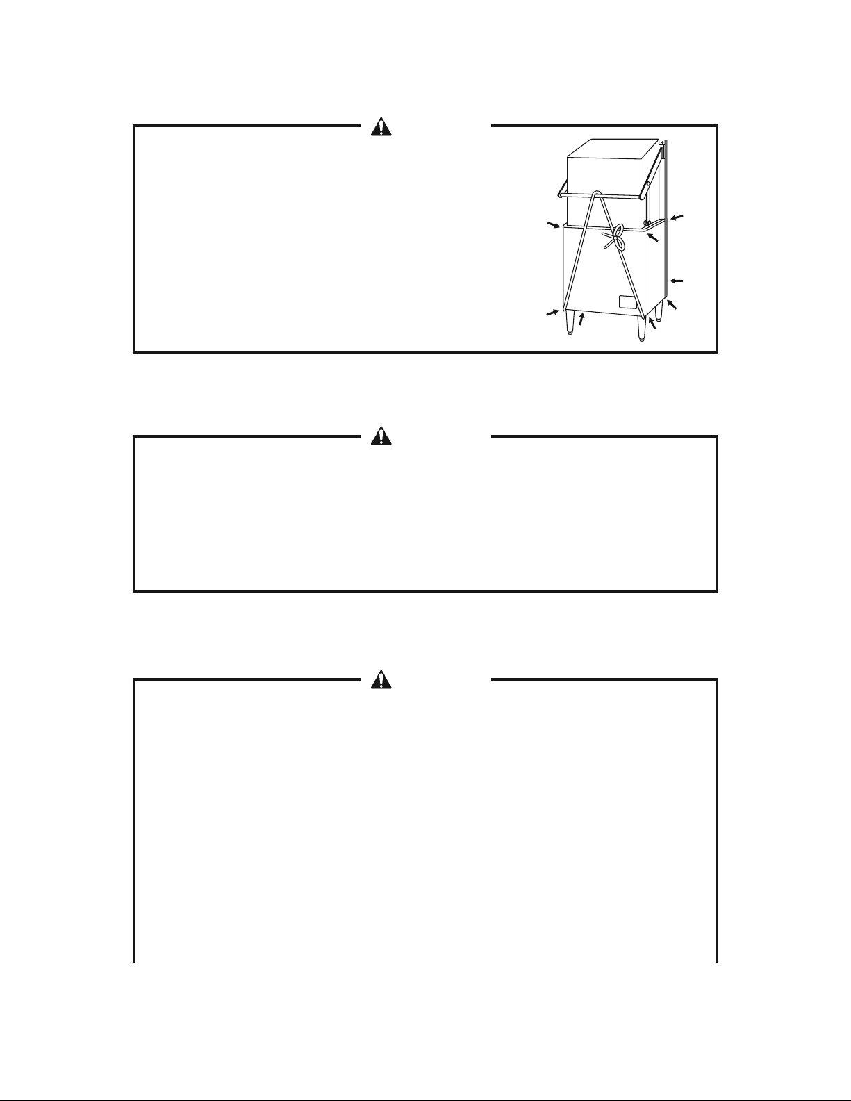
WARNING
When handling the unit (unloading from pallet,
moving, installing), do not hold the door or handle, or
the door will open. Hold the parts indicated by arrows
only.
Do not remove the shipping band securing the door until the end of installation.
WARNING
1. Do not lay down the unit. The door may open and cause injury.
2. This is a heavy unit. Handle and move it with care to prevent injury.
3. When unpacking or moving the unit, be careful not to damage the parts on
the bottom.
2. INSTALLATION
WARNING
1. This product must be installed in accordance with applicable national, state,
and local regulations.
2. To prevent possible water leak, electric shock or fire, the installation must be
carried out by qualified personnel according to this manual. On completion
of the installation, start up the unit to check for any abnormalities, and
instruct the user on how to use and maintain the unit in accordance with the
Instruction Manual.
3. This unit is not intended for outdoor use. Exposure to rain may cause electric
leakage or shock.
4. To prevent fire, electric shock, injury or water leak, this unit should be
1
disassembled, repaired or modified only by qualified service personnel.
5. The location should provide a firm and level foundation for the unit to avoid
the risk of water leaks or injury caused by overturn or fall.
6. Avoid a site where dripping is not allowed. The unit may drip water onto the
floor.
7. Ambient temperature should be within 41 to 95°F (5 to 35°C). Operation of
the unit for extended periods outside of this normal temperature range may
affect performance.
8. Do not install the unit where there is a risk of freezing. If there is a possibility
that the ambient temperature may fall below 32°F (0°C) and freeze the unit,
be sure to drain the unit. The water supply line could be damaged and leak
water, resulting in damage to the surrounding property.
9. Install the unit where high temperatures and steam are allowed. During
operation, the surface temperature will reach around 176°F (80°C), and
steam will come out from between the door and body.
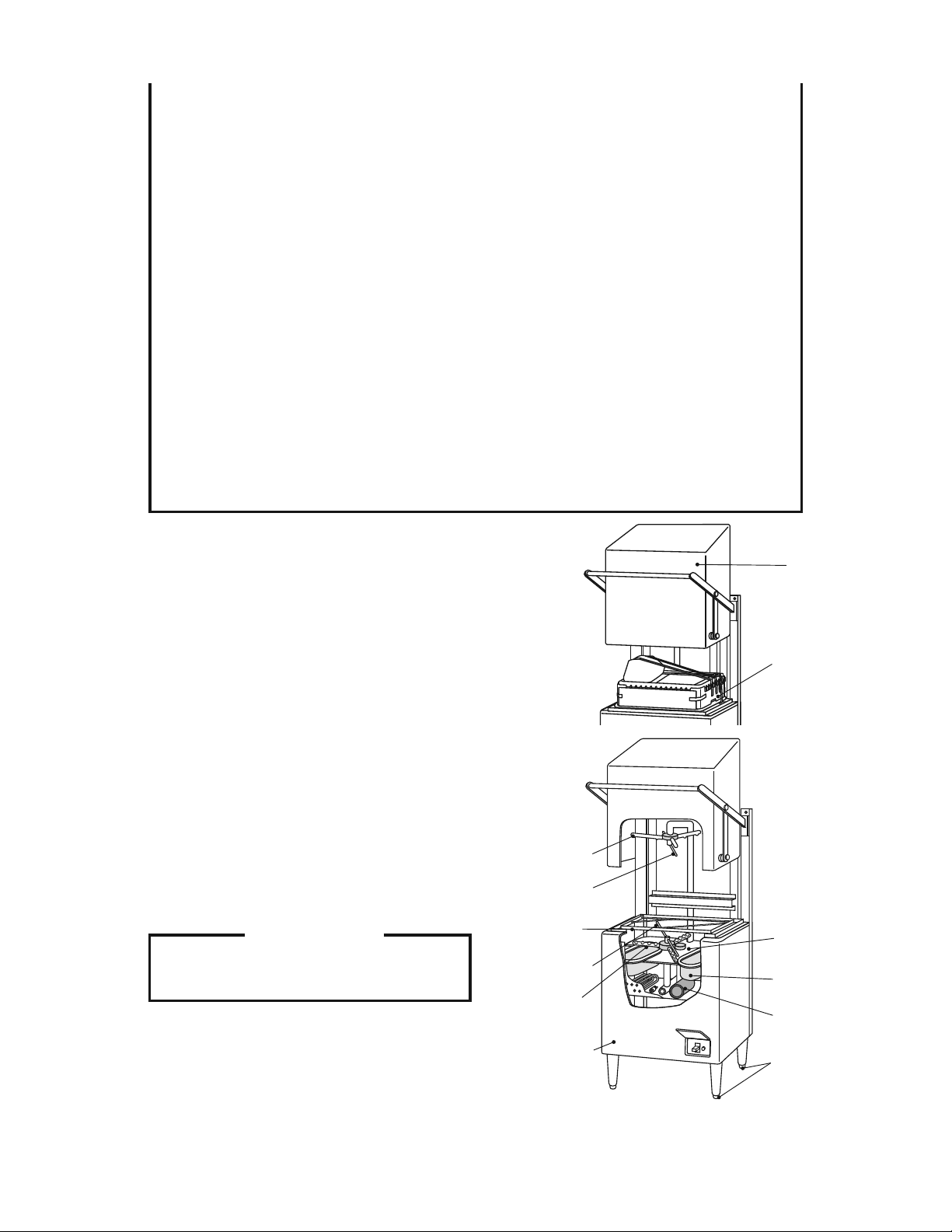
[a] SHIPPING TAPE
1) Remove the shipping band from the door.
2) Remove the shipping tape from the exterior.
3) Remove the shipping band from the rack
and package of accessories.
4) Remove the shipping tape from the rack rail.
5) Remove the shipping tape from the upper
and lower spray arms.
6) Remove the shipping tape from the tank
filters and separator. Take out the tank
filters.
IMPORTANT
Do not remove the labels.
Upper Wash
Spray Arm
Upper Rinse
Spray Arm
Rack Rail
Lower Rinse
Spray Arm
Lower Wash
Spray Arm
Door
Accessories
in Rack
Separator
Tank Filter
Pump Filter
2
Front Panel
Adjustable Leg
[b] CHECKS BEFORE INSTALLATION
1) Check the exterior including the front panel and door for damage.
2) Check the internal parts including the spray arms and filters for damage or clogging.
3) The accessories except the rack are provided in the package. Check that all the
accessories listed in the instruction manual (see “1. [c] ACCESSORIES”) are included
and not damaged.
IMPORTANT
1. Visually inspect the exterior of the shipping container and immediately report
any damage to the carrier. Upon opening the container, any concealed
damage should also be immediately reported to the carrier.
2. The instruction manual should be handed over to the user.
[c] PROTECTIVE FILM
Be sure to remove the protective plastic film from the door and other parts which may
become hot during operation. Otherwise the adhesive on the film will make the stainless
steel exterior look unclean.
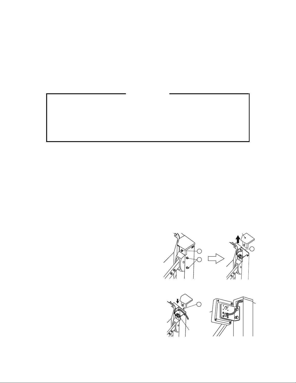
[d] OPERATION PANEL
Be sure to attach the operation panel before installing the unit. It is prepared at the factory
to be attached to the right side of the unit.
1) Loosen screws A on the pillar at the right side
Frame Cover
of the body (no need to remove). Then, remove
screw B at the front of the pillar to take off the
frame cover.
㪙
㪘
㪚
2) Insert the operation panel cable into the frame
(C), and route it into the machine compartment.
Then, attach the operation panel. Be careful not
to let the wiring touch the door opener.
3) Remove the front panel, and pull the cable from
the back of the machine compartment.
㪚
4) Remove the plastic bag from the operation
panel connection cable coming out of the
control box, and connect these cables.
Door Opener
3
 Loading...