

Hoshizaki America JWE-2400CUA-L-25B Installation Manual

DISHWASHER
INSTRUCTION MANUAL
JWE-2400CUA-L-25B
JWE-2400CUA-R-25B
FOR END USER
L1J002111 (041811)

IMPORTANT
Only qualified service technicians should install, service and maintain the
product. No installation, service or maintenance should be undertaken until
the technician has thoroughly read this Instruction Manual. Likewise, the
owner/manager should not proceed to operate the product until the installer
has instructed them on its proper operation. Failure to install, operate, and
maintain the equipment in accordance with this manual may adversely affect
safety, performance, component life, and warranty coverage.
Hoshizaki provides this manual primarily to assist qualified service technicians in the
installation, maintenance, and service of the product.
Should the reader have any questions or concerns which have not been satisfactorily
addressed, please call, write, or send an e-mail message to the Hoshizaki Technical
Support Department for assistance.
HOSHIZAKI AMERICA, INC.
618 Highway 74 South
Peachtree City, GA 30269
Attn: Hoshizaki Technical Support Department
Phone: 1-800-233-1940 Technical Support
(770) 487-2331
Fax: 1-800-843-1056
(770) 487-3360
E-mail: techsupport@hoshizaki.com
Web Site: www.hoshizaki.com
NOTE: To expedite assistance, all correspondence/communication MUST include the
following information:
* Model Number
* Serial Number
* Complete and detailed explanation of the problem.
i

IMPORTANT
This manual should be read carefully before the product is installed and
operated. Only qualified service technicians should install, service, and
maintain the product. Read the warnings contained in this booklet carefully as
they give important information regarding safety. Please retain this booklet for
any further reference that may be necessary.
CONTENTS
1. CONSTRUCTION --------------------------------------------------------------------------------------1
[a] GENERAL --------------------------------------------------------------------------------------------1
[b] OPERATION PANEL -------------------------------------------------------------------------------3
[c] CONVEYOR SPEED SWITCH ------------------------------------------------------------------4
[d] ACCESSORIES -------------------------------------------------------------------------------------4
[e] PERIODICAL REPLACEMENT PARTS ------------------------------------------------------5
2. CHECKS BEFORE OPERATION -------------------------------------------------------------------5
[a] CHECKS AFTER INSTALLATION --------------------------------------------------------------5
[b] WATER REQUIREMENTS -----------------------------------------------------------------------5
[c] CHECKS BEFORE OPERATION---------------------------------------------------------------6
3. CHECKING THE DETERGENT TANK AND RINSE AID TANK -----------------------------7
4. CHECKING THE OPERATION BOX ---------------------------------------------------------------7
5. CHECKING THE TABLE LIMIT SWITCH ---------------------------------------------------------7
6. PREPARING THE WASH COMPARTMENT -----------------------------------------------------7
[a] AUTO FILL -------------------------------------------------------------------------------------------8
PAGE
7. LOADING -------------------------------------------------------------------------------------------------9
[a] PREWASH -------------------------------------------------------------------------------------------9
[b] LOADING DISHES ---------------------------------------------------------------------------------9
[c] LOADING RACKS -------------------------------------------------------------------------------- 10
8. WASH AND RINSE ----------------------------------------------------------------------------------- 10
[a] OPERATING TEMPERATURES -------------------------------------------------------------- 10
[b] RACK CONVEYOR SPEED AND WASH INITIATION ---------------------------------- 10
9. UNLOADING --------------------------------------------------------------------------------------------11
10. INSUFFICIENT WASHING RESULTS ---------------------------------------------------------- 12
11. SHUTDOWN ------------------------------------------------------------------------------------------- 13
ii

12. INTERRUPTION -------------------------------------------------------------------------------------- 14
13. EMERGENCY STOP -------------------------------------------------------------------------------- 14
14. DAILY MAINTENANCE ----------------------------------------------------------------------------- 15
15. WEEKLY MAINTENANCE -------------------------------------------------------------------------- 20
[a] HEATER -------------------------------------------------------------------------------------------- 20
[b] EXTERIOR ----------------------------------------------------------------------------------------- 20
16. MONTHLY INSPECTION --------------------------------------------------------------------------- 20
[a] WATER SUPPLY LINE -------------------------------------------------------------------------- 20
17. TROUBLESHOOTING ------------------------------------------------------------------------------ 21
[a] TROUBLES REQUIRING IMMEDIATE SERVICE CALL -------------------------------- 21
[b] TROUBLES REQUIRING CHECK BY USER ---------------------------------------------- 21
[c] TROUBLES WITHOUT ERROR CODE INDICATION ----------------------------------- 22
18. LONG STORAGE, RELOCATION, DISPOSAL, TRANSFER -----------------------------22
iii
Important Safety Information
Throughout this manual, notices appear to bring your attention to situations which could
result in death, serious injury, or damage to the unit.
WARNING
CAUTION
Indicates a situation which could result in damage to the unit.
IMPORTANT
This product should be destined only to the use for which it has been
expressly conceived. Any other use should be considered improper and
therefore dangerous. The manufacturer cannot be held responsible for injury
or damage resulting from improper, incorrect, and unreasonable use.
To reduce the risk of death, electric shock, serious injury, or fi re, follow
basic precautions including the following:
• Electrical connection must be hard-wired and must meet national, state, and
local electrical code requirements. Failure to meet these code requirements
could result in death, electric shock, serious injury, fi re, or severe damage to
equipment.
• This unit requires independent power supplies for the dishwasher and for the
booster tank. See the nameplate for proper voltage and breaker/fuse sizes.
Failure to use proper breakers or fuses can result in tripped breakers, blown
fuses, or damage to existing wiring. This could lead to heat generation or
fi re.
• THIS UNIT MUST BE GROUNDED. Failure to properly ground this unit
could result in death or serious injury.
• This unit should be disassembled or repaired only by qualified service
personnel to reduce the risk of electric shock, injury, or fi re.
• Do not make any alterations to the unit. Alterations could result in electric
shock, injury, fi re, or damage to the unit.
Indicates a hazardous situation which could result in death or
serious injury.
Indicates important information about the use and care of the
unit.
WARNING
iv
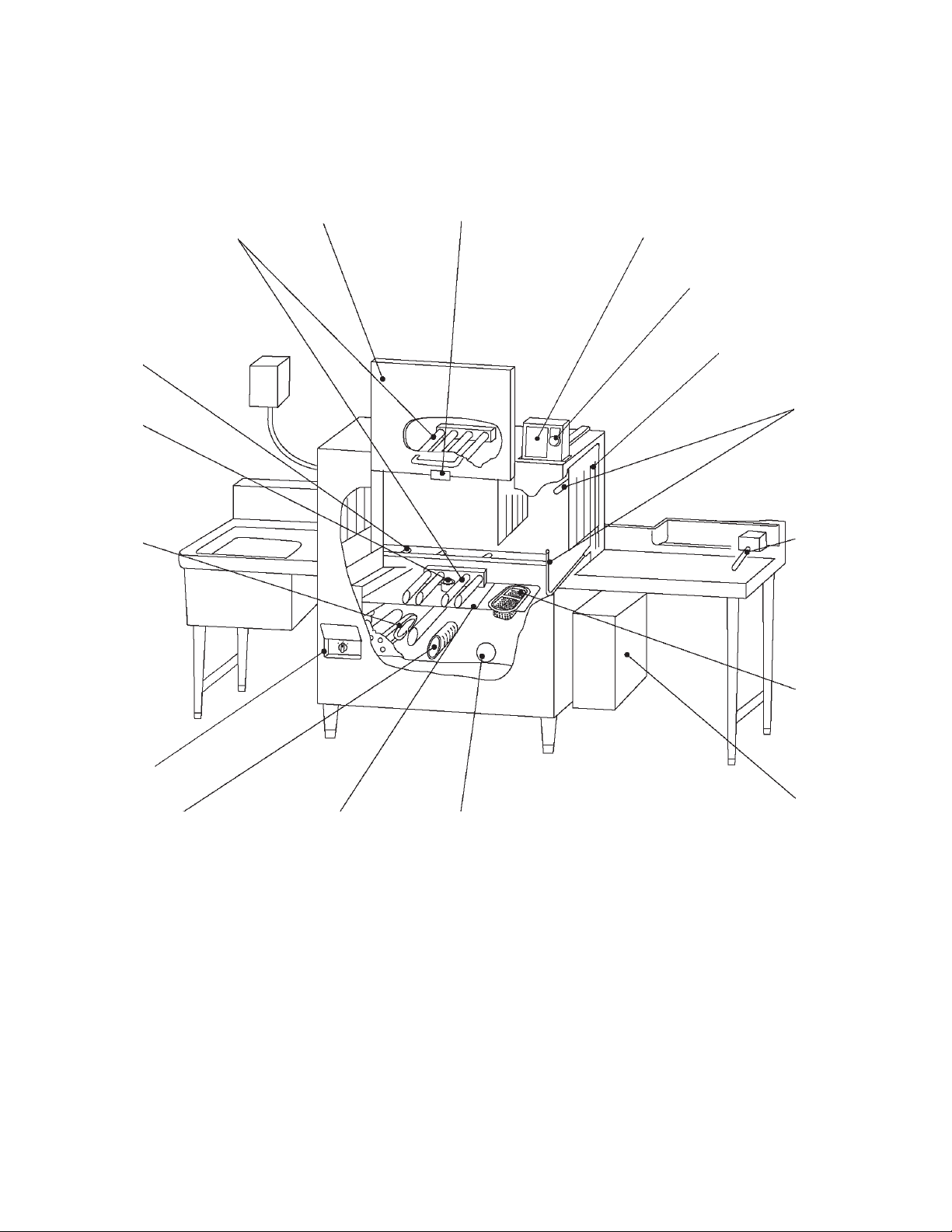
1. CONSTRUCTION
[a] GENERAL
* The illustration shows the “-L” model (rack fl ows from left to right).
[17] [16]
[1] [15]
[14]
[13]
[2]
[12]
[3]
[4] [11]
[10]
[5]
[9]
[6] [7] [8]
[1] Upper Wash Spray Arm, Lower Wash Spray Arm
Sprays wash water onto dishes.
[2] Rack Rail, Conveyor
[3] Drain Pipe
Pull out to drain.
[4] Heater
Keeps wash water at proper temperature.
1

[5] Conveyor Speed Switch
See “[c] CONVEYOR SPEED SWITCH”.
[6] Pump Filter
Prevents scraps from being drawn into the pump.
[7] Separator
[8] Water Level Sensor
Detects wash water level.
[9] Booster Tank
[10] Tank Filter
Separates wash water and scraps.
[11] Table Limit Switch
Stops washing operation when a rack reaches the end of the clean dishtable.
[12] Upper Rinse Spray Arm, Lower Rinse Spray Arm
Sprays rinse water onto dishes to rinse off detergent.
[13] Curtain
Prevents splashing from the entrance and exit of the wash compartment.
[14] Emergency Stop Button
Stops the unit in case of emergency.
[15] Operation Panel
See “[b] OPERATION PANEL”.
[16] Hook
Holds the service panel in its open position.
[17] Service Panel
2
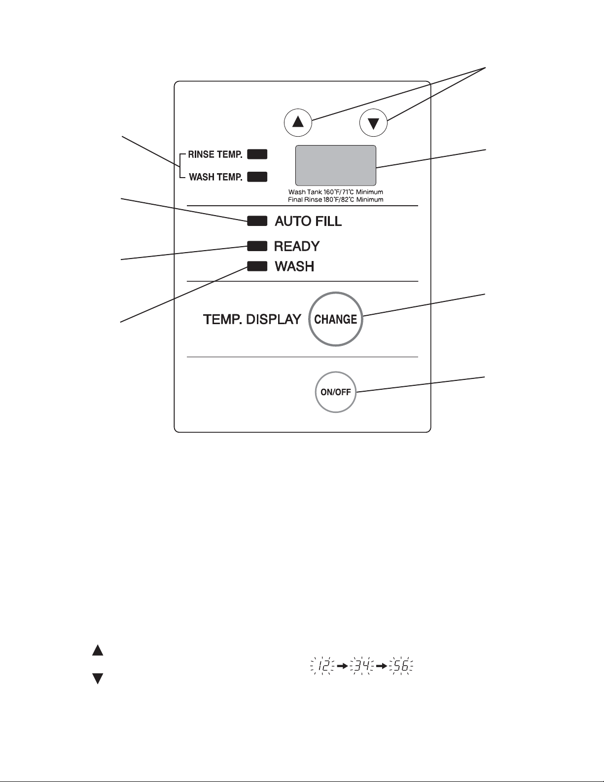
[b] OPERATION PANEL
[1]
[2]
[3]
[4]
[5]
[6]
[7]
[8]
[1] Water Temperature Lamps
Light up to indicate the water temperature shown in the display.
[2] “AUTO FILL” Lamp
Flashes during the auto fi ll cycle, and goes off at the end of the cycle.
[3] “READY” Lamp
Lights up when the auto fi ll cycle completes and the dishwasher is ready to wash.
[4] “WASH” Lamp
Lights up during washing operation.
[5] Up Button, Down Button
Indicates the total hours of operation in six digits by two digits each time.
Example: 123,456 hours are indicated by
Press to stop the beep in case of error.
Serv
ice personnel also use these buttons to change the controller settings.
3
[6] Display
Indicates wash water temperature in wash cycle, rinse water temperature in rinse
cycle, and error codes in case of trouble. See “17. TROUBLESHOOTING”.
[7] “CHANGE” Button
Press to change the wash tank water temperature shown in the display to the booster
tank water temperature.
[8] “ON/OFF” Button
Turns on/off the power for operation.
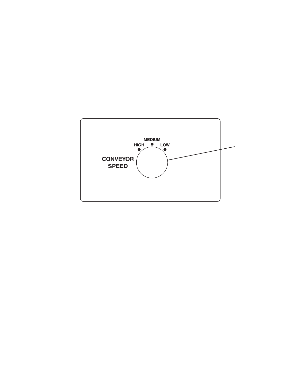
[c] CONVEYOR SPEED SWITCH
[1]
[1] Conveyor Speed Switch
Changes the rack conveyor speed in three levels (high, medium, low).
[d] ACCESSORIES
Instruction manual x 1 Installation manual x 1
Universal rack x 1 Operation sheet x 1
Required for installation:
Operation box assembly x 1 Hook - drain x 1
Guard (L), (R) x 1 each Cable cover (S) x 1
Hook - drain securing bolt w/washer
(stainless steel M6 x 12) x 1
Upper wash spray arm x 1
Cable tie x 2
Curtain (S) x 2 Curtain (L) x 1
Shaft - curtain x 3 (2 types) Table limit switch x 1
Strainer x 1 Gasket x 1
4
 Loading...