

Hoshizaki America FS-1500MLH-C Service Manual
Hoshizaki America, Inc.
Hoshizaki
Modular Cubelet Serenity Series with
"F-A" Control Board
Models
FS-1001MLH-C with SRC-10H
“A Superior Degree
of Reliability”
www.hoshizaki.com
FS-1022MLH-C with SRC-10H
FS-1500MLH-C with SRC-14H
SERVICE MANUAL
Number: 73203
Issued: 1-5-2015
Revised: 1-7-2015
WARNING
Only qualied service technicians should install and service the appliance. To
obtain the name and phone number of your local Hoshizaki Certied Service
Representative, visit www.hoshizaki.com. No service should be undertaken until
the technician has thoroughly read this Service Manual. Failure to service and
maintain the appliance in accordance with this manual will adversely affect safety,
performance, component life, and warranty coverage and may result in costly water
damage. Proper installation is the responsibility of the installer. Product failure or
property damage due to improper installation is not covered under warranty.
Hoshizaki provides this manual primarily to assist qualied service technicians in the
service of the appliance.
Should the reader have any questions or concerns which have not been satisfactorily
addressed, please call, send an e-mail message, or write to the Hoshizaki Technical
Support Department for assistance.
Phone: 1-800-233-1940; (770) 487-2331
Fax: 1-800-843-1056; (770) 487-3360
E-mail: techsupport@hoshizaki.com
HOSHIZAKI AMERICA, INC.
618 Highway 74 South
Peachtree City, GA 30269
Attn: Hoshizaki Technical Support Department
Web Site: www.hoshizaki.com
NOTE: To expedite assistance, all correspondence/communication MUST include the
following information:
• Model Number
• Serial Number
• Complete and detailed explanation of the problem.
2

IMPORTANT
This manual should be read carefully before the appliance is serviced. Read
the warnings and guidelines contained in this manual carefully as they provide
essential information for the continued safe use, service, and maintenance of the
appliance. Retain this manual for any further reference that may be necessary.
CONTENTS
Important Safety Information ................................................................................................. 5
I. Construction and Water/Refrigeration Circuit Diagram ....................................................... 8
A. Construction .................................................................................................................. 8
1. Icemaker .................................................................................................................. 8
2. Condensing Unit ...................................................................................................... 9
3. Icemaking Unit ....................................................................................................... 10
B. Water/Refrigeration Circuit Diagram .............................................................................11
II. Sequence of Operation and Service Diagnosis ............................................................... 12
A. Sequence of Operation Flow Chart ............................................................................. 12
1. Icemaking and Drain Cycle .................................................................................... 12
2. Shutdown .............................................................................................................. 13
B. Service Diagnosis ....................................................................................................... 14
C. Control Board Check ................................................................................................... 22
D. Bin Control Check ....................................................................................................... 27
E. Float Switch Check and Cleaning ............................................................................... 31
F. Diagnostic Tables ......................................................................................................... 33
III. Controls and Adjustments ............................................................................................... 36
A. Control Board .............................................................................................................. 36
1. Control Board Layout ............................................................................................. 37
2. LED Lights and Audible Alarm Safeties ................................................................. 38
3. Ice Purge Cycle Bypass ......................................................................................... 39
B. Controls and Adjustments ........................................................................................... 39
1. Default Dip Switch Settings .................................................................................... 39
2. BC1 (Infrared Sensor) Shutdown Delay (S1 dip switch 1, 2, 3) ............................ 40
3. Drain Frequency Control (S1 dip switch 4) ............................................................ 40
4. Continuous Dispensing Timer (S1 dip switch 5 & 6) .............................................. 40
5. Bin Control Selector (S1 dip switch 7) ................................................................... 41
6. BC (Mechanical Stand-Alone) Shutdown Delay (S1 dip switch 8) ......................... 41
7. Factory Use (S1 Dip Switch 9 & 10) ....................................................................... 41
C. Power Switch and Control Switch ................................................................................ 42
IV. Refrigeration Circuit and Component Service Information.............................................. 43
A. Refrigeration Circuit Service Information .................................................................... 43
B. Component Service Information .................................................................................. 46
V. Maintenance .................................................................................................................... 55
VI. Disposal .......................................................................................................................... 57
3

VII. Technical Information ..................................................................................................... 58
A. Specication and Performance Data ........................................................................... 58
1. FS-1001MLH-C with SRC-10H ............................................................................... 58
2. FS-1022MLH-C with SRC-10H .............................................................................. 59
3. FS-1500MLH-C with SRC-14H .............................................................................. 60
4. SRC-10H and SRC-14H ........................................................................................ 61
B. Wiring Diagram ............................................................................................................ 62
1. Icemaker ................................................................................................................ 62
2. Condensing Unit .................................................................................................... 63
4
Important Safety Information
Throughout this manual, notices appear to bring your attention to situations which could
result in death, serious injury, damage to the appliance, or damage to property.
WARNING Indicates a hazardous situation which could result in death or
serious injury.
NOTICE Indicates a situation which could result in damage to the
appliance or property.
IMPORTANT Indicates important information about the use and care of the
appliance.
WARNING
The appliance should be destined only to the use for which it has been expressly
conceived. Any other use should be considered improper and therefore dangerous.
The manufacturer cannot be held responsible for injury or damage resulting from
improper, incorrect, and unreasonable use. Failure to service and maintain the
appliance in accordance with this manual will adversely affect safety, performance,
component life, and warranty coverage and may result in costly water damage.
To reduce the risk of death, electric shock, serious injury, or re, follow basic
precautions including the following:
• Only qualied service technicians should install and service the appliance.
• The appliance must be installed in accordance with applicable national, state, and
local codes and regulations. Failure to meet these code requirements could result in
death, electric shock, serious injury, re, or damage to the appliance.
• The appliance must be installed in accordance with applicable national, state, and
local codes and regulations.
• To reduce the risk of electric shock, do not touch the icemaker power switch or plug
with damp hands. Make sure the icemaker power switch is in the "OFF" position
before plugging in or unplugging the icemaker.
• Before Servicing: FS: Move the icemaker's power switch to the "OFF" position.
Unplug the icemaker from the electrical outlet. SRC: Turn off the power supply
to the remote condensing unit. Place the disconnect (if applicable) in the off
position. Lockout/Tagout to prevent the power supply from being turned back on
inadvertently.
• Do not make any alterations to the icemaker or condensing unit. Alterations could
result in electric shock, injury, re, or damage to the appliance.
5
WARNING, continued
FS
• The icemaker requires an independent power supply of proper capacity. See the
nameplate for electrical specications. Failure to use an independent power supply
of proper capacity can result in a tripped breaker, blown fuse, damage to existing
wiring, or component failure. This could lead to heat generation or re.
• THE ICEMAKER MUST BE GROUNDED. The icemaker is equipped with a
NEMA5-15 three-prong grounding plug to reduce the risk of potential shock
hazards. It must be plugged into a properly grounded, independent 3-prong wall
outlet. If the outlet is a 2-prong outlet, it is your personal responsibility to have
a qualied electrician replace it with a properly grounded, independent 3-prong
wall outlet. Do not remove the ground prong from the power cord and do not use
an adapter plug. Failure to properly ground the icemaker could result in death or
serious injury.
• Do not use an extension cord.
• Do not use an icemaker with a damaged power cord. The power cord should not be
altered, jerked, bundled, weighed down, pinched, or tangled. Such actions could
result in electric shock or re. To unplug the icemaker, be sure to pull the plug, not
the cord, and do not jerk the cord.
• Do not place ngers or any other objects into the ice discharge opening.
SRC
• The remote condensing unit requires an independent power supply of proper
capacity. See the nameplate for electrical specications. Failure to use an
independent power supply of proper capacity can result in a tripped breaker, blown
fuse, damage to existing wiring, or component failure. This could lead to heat
generation or re.
• Electrical connection must be hard-wired to the remote condensing unit and must
meet national, state, and local electrical code requirements. Failure to meet these
code requirements could result in death, electric shock, serious injury, re, or
damage.
• THE REMOTE CONDENSER UNIT MUST BE GROUNDED. The power supply and
ground connection to the remote condenser unit are supplied from the icemaker.
Failure to properly ground the remote condenser unit could result in death or
serious injury.
• Wire routing (conduit) and disconnect (if required) must meet national, state, and
local electrical code requirements. Failure to meet these code requirements could
result in death, electric shock, serious injury, re, or damage.
6

NOTICE
• Follow the instructions in this manual carefully to reduce the risk of costly water
damage.
• In areas where water damage is a concern, install in a contained area with a oor
drain.
• Install the appliance in a location that stays above freezing. Normal operating
ambient temperature must be within 45°F to 100°F (7°C to 38°C).
• Do not leave the icemaker on during extended periods of non-use, extended
absences, or in sub-freezing temperatures. To properly prepare the icemaker for
these occasions, follow the instructions provided in the instruction manual.
• Do not place objects on top of the appliance.
• The dispenser unit/ice storage bin is for ice use only. Do not store anything else in
the dispenser unit/ice storage bin.
7
I. Construction and Water/Refrigeration Circuit Diagram
A. Construction
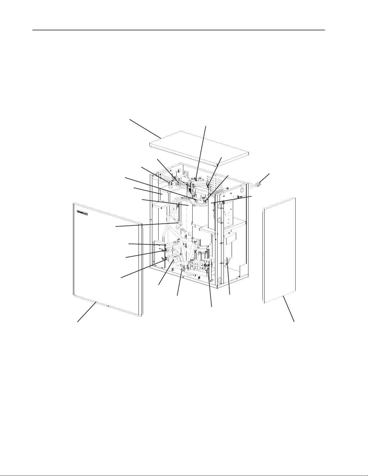
1. Icemaker
Top Panel
Inlet Water Valve
Cutter, Extruding Head, Evaporator
Reservoir
Ice Chute
Thermostatic
Expansion Valve
Strainer
High-Side
Service Valve
Low-Side
Service Valve
Float Switch
Drier
BC2 (mechanical backup)
Spout
Evaporator
Heater
Control Box
Power Cord
BC1 (infrared sensor)
Front Panel Right Side
Model Shown: FS-1500MLH-C
Gear Motor
Drain Valve
Panel
8
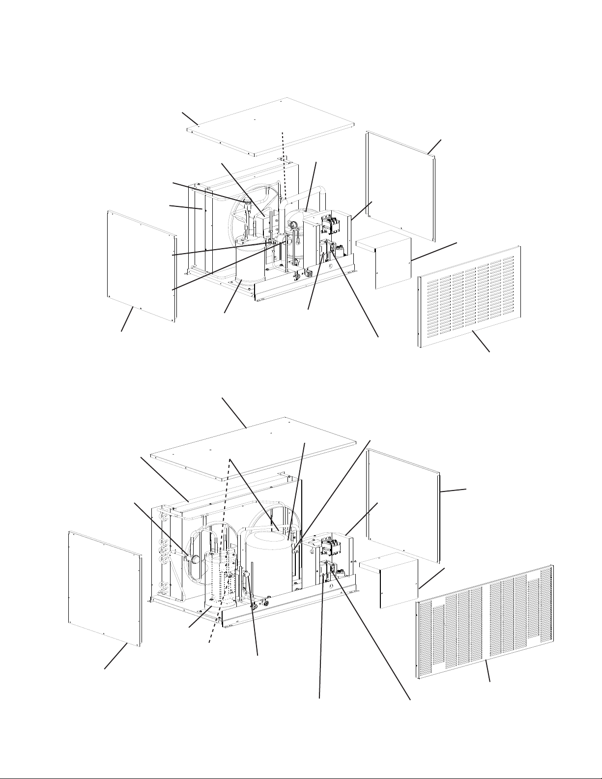
2. Condensing Unit
a) SRC-10H
Top Panel
Headmaster (C.P.R.)
Condenser
High-Side
Service Valve
Low-Side
Service Valve
Left Side Panel
b) SRC-14H
High-Pressure Switch
Fan Motor
Receiver
Top Panel
Compressor
Control Low-Pressure
Switch
Safety Low-Pressure
Switch
Right Side Panel
Control Box
Control Box Cover
Louver Panel
Condenser
Headmaster (C.P.R.)
Receiver
Left Side Panel
Fan Motors
High-Side
Service Valve
Compressor
Low-Side
Service Valve
Control Low-Pressure Switch
High-Pressure Switch
Right Side Panel
Control Box
Control Box Cover
Louver Panel
Safety Low-Pressure Switch
9
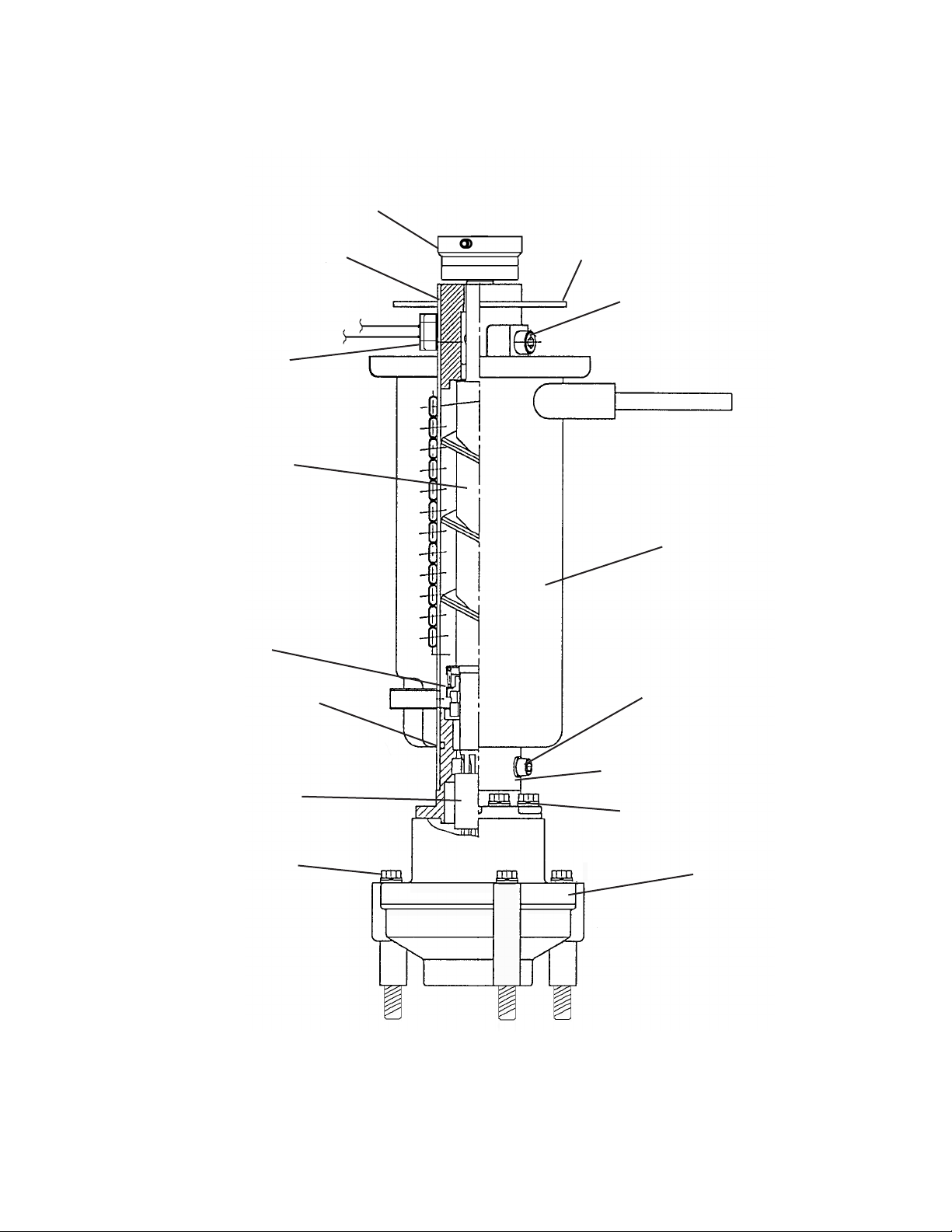
3. Icemaking Unit
Cutter
Extruding Head and
Upper Bearing
Evaporator Heater
Auger
Mechanical Seal
O-Ring
Evaporator Flange
Seal Bolts and Washers
Evaporator
Socket Head Cap Screw
and Split Lock Washer
Spline Coupling
Socket Head Cap Screw
and Split Lock Washer
Housing and
Lower Bearing
Hex Bolt and Washer
Gear Motor
10
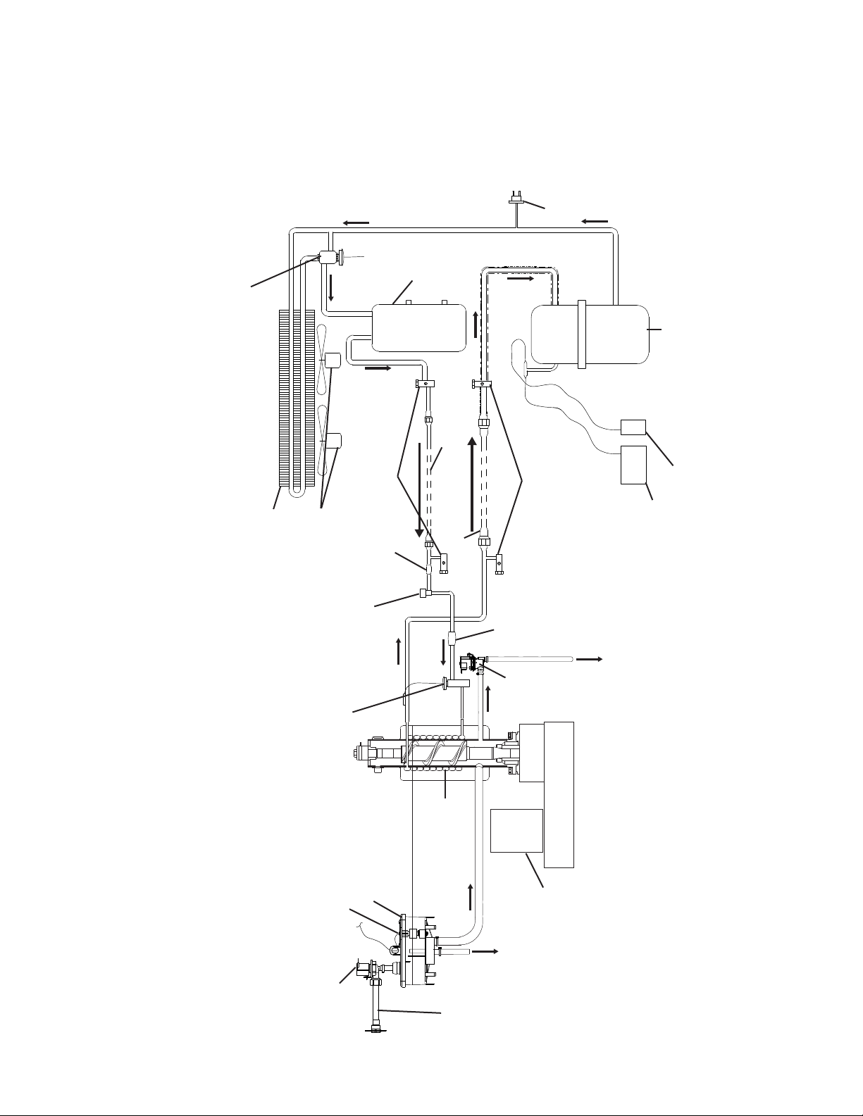
B. Water/Refrigeration Circuit Diagram
Receiver
Headmaster (C.P.R.)
High-Pressure
Switch
SRC
FS
Condenser
Fan Motors
High-Side
Service
Strainer
Pump-Down
Solenoid Valve
Expansion Valve
Valves
Liquid Line
Suction Line
Drier
Drain
Low-Side
Service
Valve
Valves
Control Low-Pressure Switch
Drain Outlet
Compressor
Safety Low-Pressure Switch
Inlet
Water
Float Switch
Valve
Reservoir
Evaporator
Water Level
Gear
Motor
Overow
Water
Supply
Line
11
II. Sequence of Operation and Service Diagnosis
A. Sequence of Operation Flow Chart
1. Icemaking and Drain Cycle
WV continues
GM de-energized
Low Water Safety
Shutdown
90. sec. PT terminates
unit shuts down and
1-beep alarm continues.
When UFS closes, alarm
resets and 2. Ice Purge
Cycle starts.
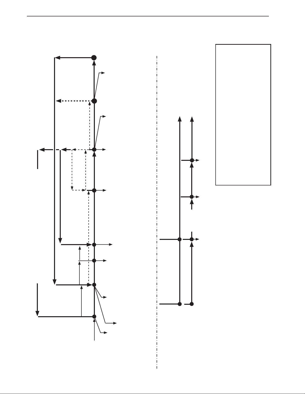
Normal Operation
UFS open
WV energized
PDS de-energized
(CLPS opens)
Comp de-energized
FMR de-energized
GM continues
90 sec.
90 sec. FT exceeded, 90
sec. PT starts and 1-beep
Purge Timer
Rell
alarm sounds
FT Maximum
90 sec.
LFS closed
FT off (90 sec.)
UFS closed
FZT starts (30 min.)
FT terminated
WV de-energized
Comp continues
EH continues
FMR continues
GM continues
PDS continues
Low Water Safety
FMR-fan motor-remote
FT-ll timer (low water safety)
FZT-freeze timer
GM-gear motor
LFS-lower oat switch
PDS-pump-down solenoid valve
PT-purge timer
UFS-upper oat switch
WV-inlet water valve
to "1. Fill Cycle" above
4. Icemaker Restart
10-min. DT terminated
DV de-energized
1-in-12 DT reset
Legend:
BC1-bin control 1 (infrared sensor)
BC2-bin control 2 (mechanical backup)
CB-control board
CCH-crankcase heater
CLPS-control low-pressure switch
Comp-compressor
DC-drain cycle
DT-drain timer
DV-drain valve
EH-evaporator heater
4. 1-in-12 Drain Cycle - Although the factory default 1-in-1 drain cycle
is recommended, a 1-in-12 drain cycle is available. For 1-in-12 drain cycle
sequence, see "3. 1-in-12 Hour Drain Cycle & Restart (optional)."
3. Freeze Cycle
2. Ice Purge Cycle
1. Fill Cycle
1-in-1 drain cycle. DV opens for 2 sec.
every hour (CB S1 Dip Switch 4).
To bypass, press the
"SERVICE" button after
3. 10-Min. Drain
UFS open
LFS open (WV on)
FT starts (90 sec.)
FZT terminated
WV energized
Comp continues
EH continues
FMR continues
GM continues
PDS continues
30-min. FZT
DV de-energizes, no interruption
in ice procuction
Icemaker status does not change.
5 min.
GM starts.
5 or 30 sec.
(S1 Dip Switch 7)
and sounds a 5-beep alarm.
PDS energized
CLPS closed
Comp energized
FMR energized
EH continues
GM continues
EH energized
GM energized
FZT exceeded (LFS does not
2. Continued Operation
open): CB shuts down icemaker
2. Ice Purge Cycle
DV energized
GM de-energized
5 min.
Comp de-energized
FMR de-energized
PDS de-energized
GM continues
DV energizes for 2 sec.
operation
1. DT Initiates DC
FT Maximum
90 sec.
LFS closed
UFS closed
1. DT Initiates DC
Continued uninterrupted
FZT starts
FT terminated
WV de-energized
FS Models "F-A" Control Board Sequence of Operation Flow Chart - Icemaking and Drain Cycle
1. Startup
Power Switch "ON"
Control Switch in "ICE"
POWER OK LED on
BC1 Green LED on
Startup
BC1 Yellow LED off
BC2 Closed
WV energized
If Fill > 90 sec. FT
1-beep alarm sounds
WV continues
When UFS closes
alarm resets and
2. Ice Purge Cycle starts.
12
2. 1-in-1 Drain Cycle
(CB S1 dip switch 4 "OFF")
& Restart (optional)
(CB S1 dip switch 4 "ON")
3. 1-in-12 Drain Cycle
Note: CCH energizes when power is supplied to the
SRC. CCH de-energizes when Comp is de-energized.
See "VIII.B.2. Condensing Unit."
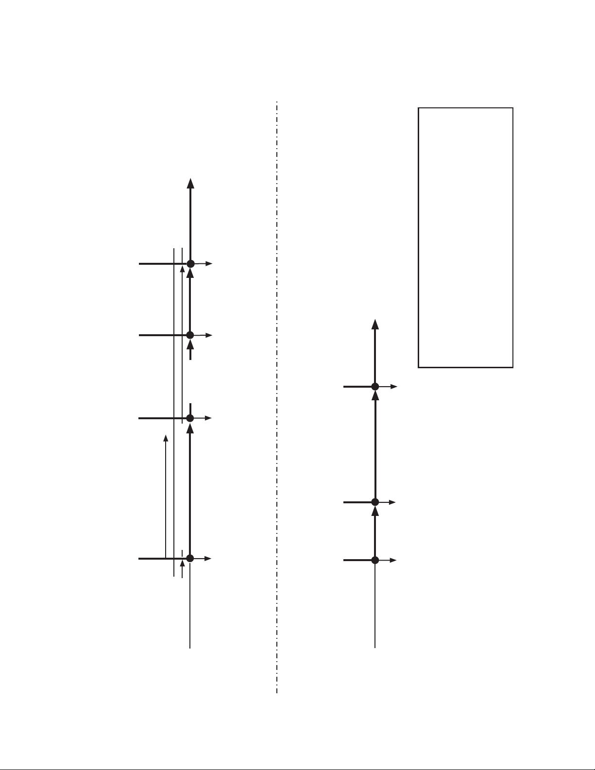
2. Shutdown
4. Icemaker Restart
3. Icemaker Off
to "2. Ice Purge Cycle" in
Icemaking and Drain Cycle
BC1 Green LED on
BC1 Yellow LED off
Chart
FMR-fan motor-remote
FT-ll timer (low water safety)
FZT-freeze timer
GM-gear motor
LFS-lower oat switch
PDS-pump-down solenoid valve
PT-purge timer
UFS-upper oat switch
WV-inlet water valve
BC1 de-activated
to "2. Ice Purge Cycle" in
Icemaking and Drain Cycle
Chart
2. Ice Purge Cycle
1. Bin Full
BC1 delay determined by CB S1 dip
switch 1, 2, 3
5 min.
BC1 Yellow LED (ashing or steady)
GM de-energized
PDS de-energized
(CLPS opens)
Comp de-energized
FMR de-energized
BC1 activated
GM continues
EH continues
2. Icemaker Off 3. Icemaker Restart
1. Bin Full
Ice level lowered
Legend:
BC2 de-activated (closed)
All Components de-energized
BC2 activated (open)
BC1-bin control 1 (infrared sensor)
BC2-bin control 2 (mechanical backup)
CB-control board
CLPS-control low-pressure switch
Comp-compressor
DC-drain cycle
DT-drain timer
DV-drain valve
EH-evaporator heater
"FS Models F-A" Control Board Sequence of Operation Flow Chart - Shutdown
1. BC1 (infrared sensor) Shutdown
BC1 Green LED on
BC1 Yellow LED off
BC2 Closed
If BC1 fails to shutdown the icemaker,
BC2 opens and a 9-beep alarm
sounds. See "II.D. Bin Control Check."
2. BC2 (mechanical backup) Shutdown
When BC2 is activated, a 9-beep alarm
sounds. See "II.D. Bin Control Check."
BC1 Green LED on
BC1 Yellow LED on
(ashing or steady)
BC2 Closed
13
B. Service Diagnosis
WARNING
• The appliance should be diagnosed and repaired only by qualied service
personnel to reduce the risk of death, electric shock, serious injury, or re.
• Risk of electric shock. Use extreme caution and exercise safe electrical practices.
• Moving parts (e.g., fan blade) can crush and cut. Keep hands clear.
• CHOKING HAZARD: Ensure all components, fasteners, and thumbscrews are
securely in place after the appliance is serviced. Make sure that none have fallen
into the dispenser unit/storage bin.
• Make sure all food zones in the icemaker and dispenser unit/storage bin are clean
after the unit is serviced.
1. Ice Production Check
To check production, prepare a bucket or pan to catch the ice and a set of scales to
weigh the ice. After the appliance has operated for 10 to 20 min., catch the ice production
for 10 min. Weigh the ice to establish the batch weight. Multiply the batch weight by
144 for the total production in 24 hours. When conrming production or diagnosing
low production, reference production information found in "VIII.A. Specication and
Performance Data."
14

2. Diagnostic Procedure
This diagnostic procedure is a sequence check that allows you to diagnose the electrical
system and components. Before proceeding, check for correct installation, proper voltage
per appliance nameplate, and adequate water pressure (10 PSIG to 113 PSIG). Check
that both the 24VAC circuit fuse and the 115VAC GM fuse are good.
Note: • When checking high voltage (115VAC), always choose a neutral (W) wire to
establish a good neutral connection.
• When checking low voltage (24VAC), always choose a neutral (LBU) wire to
establish a good neutral connection.
• When checking control board DC voltage (5VDC), always place the red positive
test lead from the multimeter to CB K5 pin closest to CB K4 connector.
See "II.C. Control Board Check."
• When checking BC1 (infrared sensor) (20VDC), check that BC1 (infrared sensor)
green LED is on. This green LED conrms 20VDC power from CB K6to BC1
(infrared sensor) and remains on constantly. If green LED is not on, check for
20VDC from CB K6 #1 (DBU) to CB K6 #3 (BR).
See "II.D.1. Bin Control1(infrared sensor) Check."
• To speed up the diagnostic process, the 5-min. ice purge cycle may be bypassed
by pressing the "SERVICE" button on the control board after the gear motor
starts. WARNING! Risk of electric shock. Care should be taken not to touch
live terminals.
• If the icemaker is in alarm, see "III.A.2. LED Lights and Audible Alarm Safeties."
• EH energizes when "GM" LED turns on.
• CB X1 relay energizes PDS. After PDS energizes, CPLS closes, then MC
energizes, energizing Comp and FMR.
• CB monitors the following switches with 5VDC during the icemaking process:
Control Switch (CS), Compressor Control Relay/Gear Motor Protect Relay (CCR/
GMPR), Float Switch (FS), and Bin Control 2 (mechanical backup).
When 5VDC is present across any of these switches, the switch is open.
1) Remove the front panel, then move the power switch to the "OFF" position. Move the
control switch to the "DRAIN" position, then move the power switch back to the "ON"
position. Replace the front panel in its correct position.
2) Allow the water system to drain for 5 min.
3) Remove the front panel. Move the power switch to the "OFF" position, then unplug the
appliance from the electrical outlet.
4) Remove the control box cover and access CB.
5) Check the CB S1 dip switch settings, see "III.B.1. Default Dip Switch Settings" to assure
that they are in the correct positions. For proper operation of BC1 (infrared sensor),
conrm that S1 dip switch 7 is in the "ON" position.
15

6) Startup – CB "POWER OK" LED is on. Plug the icemaker back into the electrical
outlet, then move the power switch to the "ON" position. Move the control switch to the
"ICE" position. CB "POWER OK" LED and BC1 green LED turn on.
Diagnosis CB "POWER OK" LED: If CB"POWER OK" LED is off, check for proper
supply voltage (115VAC) input to CT. If 115VAC is not present, check the power switch
and breaker. Next, check for proper 24VAC output voltage from CT. Check CBK8
#1 (W/R) to #2 (LBU) for 24VAC. If 24VAC is not present and 1A 24VAC fuse is good,
replace CT. If 24VAC is present and CB "POWER OK" LED is off, replace CB.
Diagnosis BC1 (infrared sensor): Check that BC1 green LED is on. If CB "POWER
OK" LED is on and BC1 green LED is off, check CB K6 #3 (BR) to CB K6 #1 (DBU)
for 20VDC. If20VDC is not present, conrm S1 dip switch 7 is in the "ON" position.
IfS1dip switch 7 is in the "ON" position and 20VDC is not present, replace CB. IfBC1
yellow LED is on or ashing, move ice away from lens. If no ice is present, clean the
lens with a warm, clean damp cloth. If BC1 yellow LED is still on or ashing after
cleaning the lens, replace BC1.
Diagnosis BC2 (mechanical backup): Check that the actuator paddle is properly
positioned. Check continuity across BC2. If open, replace BC2. Next, check VDC at CB
K8#3 (GY) to CB K8 #4 (GY). When BC2is closed 0VDC is read. Move the actuator
paddle to open BC2. When open, 5VDCis present between CB K8 #3 (GY) and CB K8
#4(GY). If 5VDC is not present when BC2 is open, replace CB. Return actuator to its
normal position.
7) Fill Cycle – "WTRIN" LED is on. Reservoir is empty and LFS and UFS are open.
FTstarts. WV energizes and ll cycle starts. LFS closes. Nothing happens at this time.
Reservoir continues to ll until UFS closes. When UFS closes, FT terminates, WV
de-energizes and CB "WTRIN" LED turns off. FZTand 30-sec. GM delay timer start.
IfUFS remains open longer than 90 sec. after LFS opens, FTexceeded and CB sounds
a 1-beep alarm. WVremains energized until UFS closes. Alarm resets automatically
when UFS closes. Diagnosis: If reservoir is empty and "WTRIN" LED is off, conrm
LFS status.
See "II.E.1. Float Switch Check." If LFS is open and "WTRIN" LED is off, replace CB.
If "WTRIN" LED is on, check that the reservoir lls. If not, check water supply line
shut-off valve, water lters, and WVscreen. If "WTRIN" LED is on and WV is off, check
CB K2 #8(W/BR) to a neutral (LBU) for 24VAC. If 24VAC is not present, check CB
K2#9(W/R) to a neutral (LBU) for 24VAC. If 24VAC is present on CB K2 #9(W/R)and
not on CB K2 #8 (W/BR), replace CB. If 24VAC is present on CB K2 #8(W/BR), check
continuity through WV solenoid. If open, replace WV. If WV is energized and rell
exceeds FT with no water in the reservoir, check for DV leaking. Ifreservoir is full and
overowing check for open UFS. See "II.E.1. Float Switch Check." If UFS is closed,
check that WV de-energizes. If not, check CB K2 #8 (W/BR) to a neutral (LBU) for
24VAC. If 24VAC is present, replace CB. IfWV de-energizes and water continues to ll
the reservoir, replace WV.
16

8) Ice Purge Cycle – "GM" LED is on. 30-sec. GM delay timer terminates, GM, EH, and
CCR/GMPR energize. Once CCR/GMPR energizes, 5VDC circuit closes through
CCR/GMPR terminal #3 (W/O) and terminal #5 (W/O) and CB K9 #5 (W/O) and
K9 #6 (W/O). After 5VDC circuit closes, 5-min. ice purge timer starts. Tobypass the
5-min. Ice Purge Cycle, press the "SERVICE" button on CB after the "GM" LED turns
on. WARNING! Risk of electric shock. Care should be taken not to touch live
terminals.
Diagnosis: If "GM" LED is off, check that UFS closes and WV de-energizes. If UFS
is closed, 30 sec. has passed, and "GM" LED remains off, replace CB. If "GM" LED is
on and GM is off, check CB K1 #3 (BR) to a neutral (W) for 115VAC. If 115VAC is not
present, check 115VAC power supply. If 115VAC is present, check CB K1 #2(W/BK)
to a neutral (W). If 115VAC is present on CB K1 #3 (BR) and not on CB K1 #2 (W/BK),
replace CB. If 115VAC is present on CB K1 #2 (W/BK), check GM fuse, GM internal
protector, GM windings and capacitor, and GM coupling between auger and GM. When
GM energizes, CCR/GMPR energizes starting 5-min. ice purge timer.
9) Freeze Cycle – "COMP" and "GM" LEDs are on. Note: CB X1 relay energizes the
PDS (pump-down solenoid) not the MC (magnetic contactor). The 5-min. ice purge
timer terminates. GM, EH, and CCR/GMPR continue. PDS energizes. Once the
refrigeration circuit low-side pressure reaches 29 PSIG, CLPS closes, energizingMC,
MC then energizes Comp and FMR. CCH de-energizes. Iceproduction starts 4 to 6 min.
after Comp energizes depending on ambient and water conditions. As ice is produced,
the water level in the reservoir drops. UFS opens. Nothing happens at this time. When
LFS opens, WV energizes and rell cycle begins, FZT terminates, and FTstarts.
FZT: 30-Min. Freeze Safety Timer – FZT starts when UFS closes and terminates
when LFS opens. If LFS does not open within 30 min. of UFS closing, CB shuts down
the icemaker and sounds a 5-beep alarm. See "III.A.2.LED Lights and Audible Alarm
Safeties." To reset, turn the power supply off and on again. See "II.F. Diagnostic Tables"
for troubleshooting details.
Icemaker Diagnosis (CCR/GMPR): 5-min. ice purge timer terminates, CB "COMP"
LED is on and PDS energizes. If not, check for 5VDC between CB K5 connector pin
closest to CB K4 connector and CB K9connector #5(W/O). If 5VDC is not present,
replace CB. If 5VDC is present, check for 5VDC between CB K5 connector pin closest
to CB K4 connector and CB K9connector #6(W/O). If 5VDC is present and CB "Comp"
LED is off (PDS not energized), replace CB. If 5VDC is not present, check for 115VAC
between CCR/GMPR terminal #7(R) to CCR/GMPR terminal #8(W) for 115VAC.
If115VAC is not present (GM not energized), see step 8 above. If 115VAC is present
and CCR/GMPR contacts are open (5VDCpresent between terminals #3(W/O) and
#5(W/O)), check CCR/GMPR solenoid voltage and solenoid continuity. Replace
CCR/GMPR if necessary.
Icemaker Diagnosis (PDS): If"COMP" LED is on and PDS is not energized, check
CB X1 relay BR wire to a neutral (W) and CB X1 relay DBU wire to a neutral (W) for
115VAC. If115VAC is present on CB X1BR wire and not on CBX1 DBU wire, replace
CB. If115VAC is present on CBX1DBU wire and PDS is not energized, check for
115VAC at PDS (DBU) to a neutral (W) for 115VAC. If 115VAC is present and PDS is
not energized, check PDS solenoid for continuity. If open or if PDS is sticking closed,
replace PDS.
17

Condensing UnitDiagnosis: Conrm that CLPS closes. Once CLPS closes, MC
energizes, energizing Comp and FMR. If not, check condensing unit 208-230VAC
power supply, breakers, disconnets. Next, conrm 115VAC from CLPS BR wire to
neutral (W). If 115VAC is not present, check wiring connections and power supply.
CLPS: When PDS is energized, CLPS closes when refrigeration circuit low-side
pressure reaches 29 PSIG. If CLPS is open, check that refrigeration circuit low-side
pressure has reached 29 PSIG. If refrigeration circuit low-side pressure is too low,
conrm proper TXV operation, check for refrigerant restrictions (drier, PDS), and correct
refrigerant charge. Recover, evacuate, and recharge if necessary. If refrigeration circuit
low-side pressure reaches 29 PSIG and CLPS does not close, replace CLPS.
SLPS: If SLPS is open, manually reset SLPS. If manually resetting SLPS does not
close contacts, replace SLPS. After resetting, conrm proper TXV operation, check for
refrigerant restriction (drier, PDS), and correct refrigerant charge. Recover, evacuate,
and recharge if necessary.
HPS: If HPS is open, HPS automatically resets when refrigeration circuit high-side
pressure is within an acceptable range. If HPS does not reset (open), allow pressures
to equalize and HPS to reset. If refrigeration circuit high-side pressure does not drop,
recover, evacuate, and recharge if necessary. Before restarting the appliance, check
for dirty or clogged condenser. Once the appliance is restarted, check for proper FMR
operation and fan blade for binding. Check receiver, service valves, PDS, and drier
for refrigeration circuit restriction. Also check for proper HM operation. If high-side
refrigerant pressures have returned to an acceptable range and HPS does not close,
replace HPS.
MC: If MC energizes and Comp does not energize, check for 115VAC at MC C2 (O) to
neutral (W). If 115VAC is not present, check CLPS, SLPS, and HPS contacts. If 115VAC
is present, check MC coil continuity. If open, replace MC. If closed, check MC L1 and
MCL2to a neutral (W) for 115VAC. If 115VAC is not present on either L1or L2, check
incoming power supply. If 115VAC is present on both L1 and L2 and Comp does not
start, check MC T1 (BK) to MC T2 (R) for 208-230VAC. If 208-230VAC is not present,
replace MC. If 208-230VAC is present, check Comp start relay, start capacitor, run
capacitor, and Comp motor windings. If FMR does not energize, check MC T3 (DBU) to
a neutral (W) for 115VAC. If 115VAC is present and FMR does not energize, check fan
motor capacitors and motor windings. If 115VAC is not present, replace MC.
18

10) Rell Cycle – "GM", "COMP", and "WTRIN" LEDs are on.
LFS opens. WVenergizes and FT starts. GM, CCR/GMPR, EH, PDS, MC, Comp, and
FMR continue. LFS closes. Nothing happens at this time. Reservoir continues to ll
until UFS closes. When UFS closes, WV de-energizes, FT terminates, and FZT starts.
IfUFS remains open longer than 90 sec. after LFS opens, FT exceeded and CB sounds
a 1-beep alarm. WVremains energized until UFS closes. Alarm resets automatically
when UFS closes.
Diagnosis – Conrm that the water level has dropped and the UFS and LFS are open.
See "II.E.1. Float Switch Check." Check that "WTRIN" LED is on. IfLFS is open and
"WTRIN" LED is off, replace CB. If "WTRIN" LED is on, check that the reservoir lls.
Ifnot, check water supply line shut-off valve, water lters, and WVscreen. If"WTRIN"
LED is on and WV is off, check CB K2 #8(W/BR) to a neutral (LBU) for 24VAC. If
24VAC is not present, check CB K2 #9(W/R) to a neutral (LBU) for 24VAC. If 24VAC
is present on CB K2 #9 (W/R)and not on CB K2#8 (W/BR), replace CB. If 24VAC is
present on CB K2#8(W/BR),check continuity through WV solenoid. If open, replace
WV. If WV is energized and rell exceeds FT with no water in the reservoir, check for DV
leaking. If reservoir is full and overowing check for open UFS. See "II.E. Float Switch
Check and Cleaning." If UFS is closed, check that WVdeenergizes. If not, check CB
K2 #8 (W/BR) to a neutral (LBU) for 24VAC. If 24VAC is present, replace CB. If WV
de-energizes and water continues to ll the reservoir, replace WV.
FT: 90-Sec. Low Water Safety Timer – When LFS opens, 90-sec. low water safety
timer starts. If UFS does not close within 90 sec. after LFS opens (FTexceeded),
CBsounds a 1-beep alarm and a 90-sec. shutdown cycle starts.
See "III.A.2.LED Lights and Audible Alarm Safeties." PDS de-energizes. Refrigeration
circuit low-side pressure drops to 9PSIG, opening CLPS. CLPS opens, de-energizing
MC, which de-energizes Comp and FMR. GM, CCR/GMPR, and EH continue. 90-sec.
purge timer terminates, GM, EH, and CCR/GMPR de-energize. WV and 1-beep alarm
continue until UFS closes.
19
 Loading...