

Hoshizaki America FH1-SSB-HD-H-0 Service Manual

NUMBER:
ISSUED:
REVISED:
73077
MARCH 8, 1999
MARCH 18, 2003
HOSHIZAKI
TempGuardTM REACH-IN
MODELS
RH1-SSB(-HD/-GD) FH1-SSB(-HD)
RH2-SSB(-HD/-GD) FH2-SSB(-HD)
RH3-SSB(-HD/-GD) FH3-SSB(-HD)
RIR2-SSB51-02
RFH2-SSB(-HD)
RFH3-SSB(-HD)
with

IMPORTANT
Only qualified service technicians should attempt to service or maintain this unit. No
service or maintenance should be undertaken until the technician has thoroughly read
this Service Manual.
HOSHIZAKI provides this manual primarily to assist qualified service technicians in the
service and maintenance of the unit.
Should the reader have any questions or concerns which have not been satisfactorily
addressed, please call or write to the HOSHIZAKI Technical Support Department for
assistance.
HOSHIZAKI AMERICA, INC.
618 Highway 74 South
Peachtree City, GA 30269
Attn: HOSHIZAKI Technical Support Department
Phone: 1-800-233-1940 Technical Service
(770) 487-2331
Fax: (770) 487-3360
NOTE: To expedite assistance, all correspondence/communication MUST include the following
information:
• Model Number
• Serial Number
• Complete and detailed explanation of the problem
2

Please review this manual. It should be read carefully before the unit is serviced or maintenance operations are performed. Only qualified service technicians should service and
maintain the unit. This manual should be made available to the technician prior to service
or maintenance.
CONTENTS
PAGE
I. ELECTRONIC CONTROL OPERATION .................................................................. 4
1. NORMAL ELECTRONIC CONTROL PROCESS
OPERATION FOR REFRIGERATOR .............................................................. 4
2. TIME - TEMPERATURE CONTROL CHART FOR REFRIGERATOR ............... 5
3. NORMAL ELECTRONIC CONTROL PROCESS .................................................
FLOW OPERATION FOR FREEZER .............................................................. 6
4. TIME - TEMPERATURE CONTROL CHART FOR FREEZER........................... 7
5. DISPLAY BOARD .............................................................................................. 8
6. ALARM / ALERT SIGNALS ............................................................................. 10
7. DEFROST FOR REFRIGERATOR .................................................................. 16
8. DEFROST FOR FREEZER .............................................................................. 16
9. START-UP DELAY........................................................................................... 16
10. PERIMETER FRAME HEATER ...................................................................... 17
11. GLASS DOOR HEATER ................................................................................. 17
12. DIAGNOSTIC MENU ....................................................................................... 17
13. CONTROL BOARD ......................................................................................... 20
FLOW ......................................
II. SERVICE DIAGNOSIS ........................................................................................... 22
III. REMOVAL AND REPLACEMENT OF COMPONENTS ....................................... 26
1. SERVICE FOR REFRIGERANT LINES ........................................................... 26
2. BRAZING ......................................................................................................... 27
3. REMOVAL AND REPLACEMENT OF COMPRESSOR ................................... 28
4. REMOVAL AND REPLACEMENT OF DRIER ................................................. 29
5. REMOVAL AND REPLACEMENT OF EXPANSION VALVE ........................... 30
6. REMOVAL AND REPLACEMENT OF EVAPORATOR .................................... 31
7. REMOVAL AND REPLACEMENT OF DOOR GASKET .................................. 31
8. REMOVAL AND REPLACEMENT OF DOOR CLOSURE SPRING .................. 32
9. REMOVAL AND REPLACEMENT OF CONTROL BOARD .............................. 33
10. DOOR RE-HINGING ......................................................................................... 34
IV. CLEANING INSTRUCTIONS ............................................................................... 35
V. WIRING DIAGRAMS ............................................................................................ 36
3
I. ELECTRONIC CONTROL OPERATION
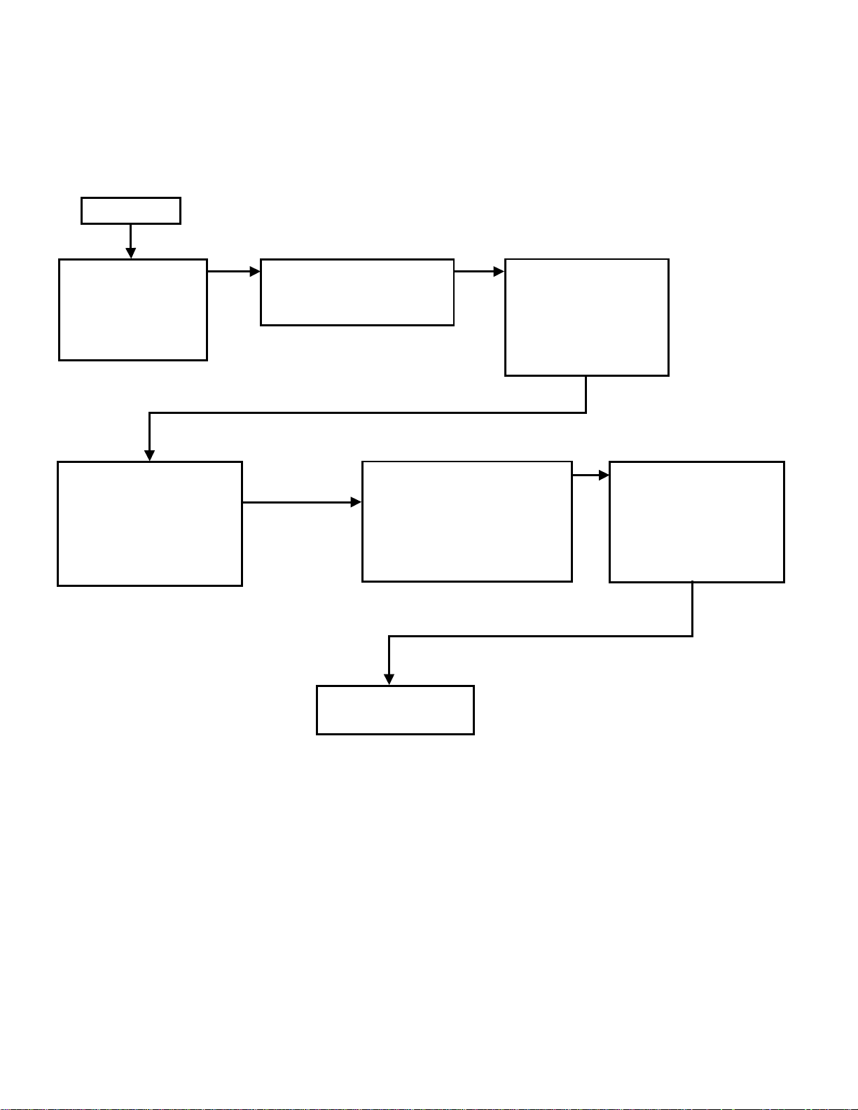
1. NORMAL ELECTRONIC CONTROL PROCESS FLOW OPERATION FOR REFRIGERATOR
POWER ON
Board Self Check
Display Read R##
(## is chip revision)
1) Frame heaters on
2) Evaporator fan on
Cycle On (Cut-on
Temperature reached)
[Minimum 2.5 minutes]
1. Compressor on
2. Condenser Fan on
(Normal Cycling)
2.5 minute delay
1. Compressor start-up
2. Condenser Fan start-up
If evaporator temperature
Continues as
normal cycling
reaches 13°F, unit initiates
defrost.
Compressor off
(Note: Condenser Fan and
Evaporator Fan are on.)
Cycle Off (Cut-out
Temperature reached)
[Minimum 2.5 minutes]
1) Compressor off
2) Condenser Fan off
(Normal Cycling)
Evaporator temperature
reaches 40°F, defrost
terminated
Compressor on
Condenser Fan on
Continues as
Normal Cycling
Note:
1) Cut-on / Cut-off / and Cabinet Temperature are read by the same sensor, called “cabinet
thermistor.
2) Defrost Thermistor reads Evaporator temperature.
4
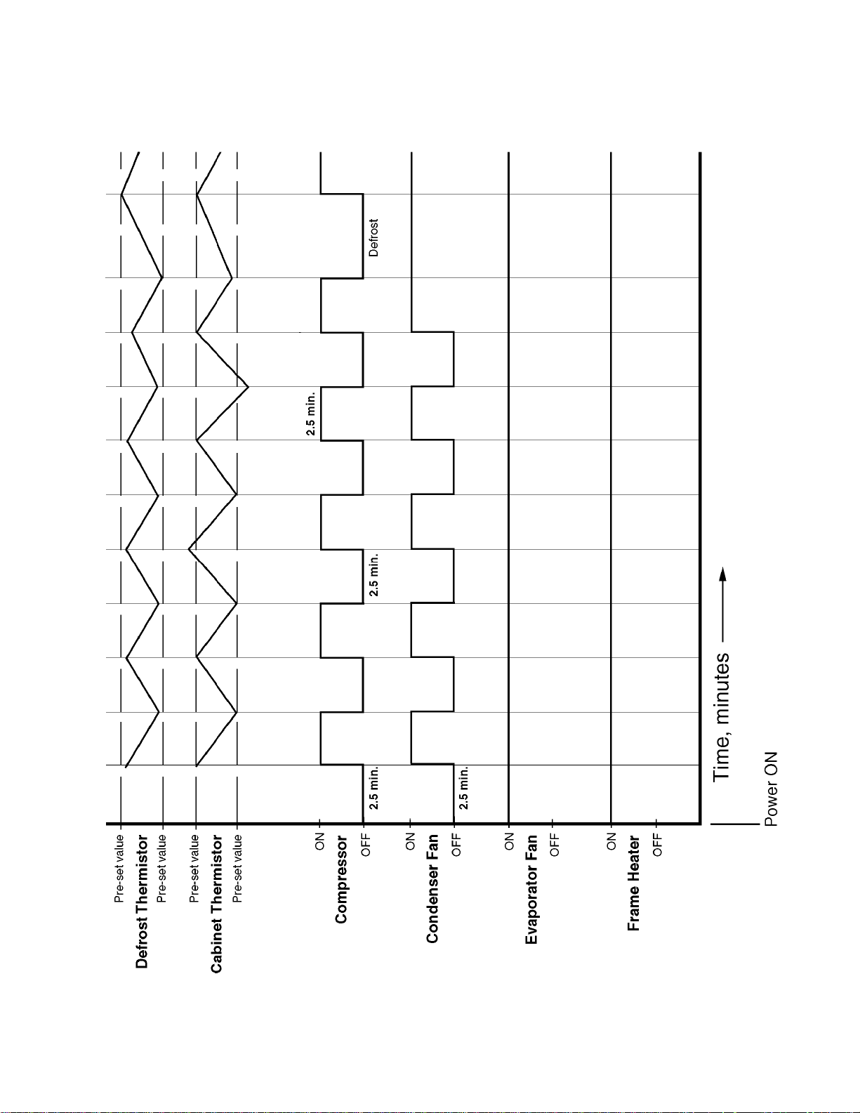
2. TIME - TEMPERATURE CONTROL CHART FOR REFRIGERATOR
5
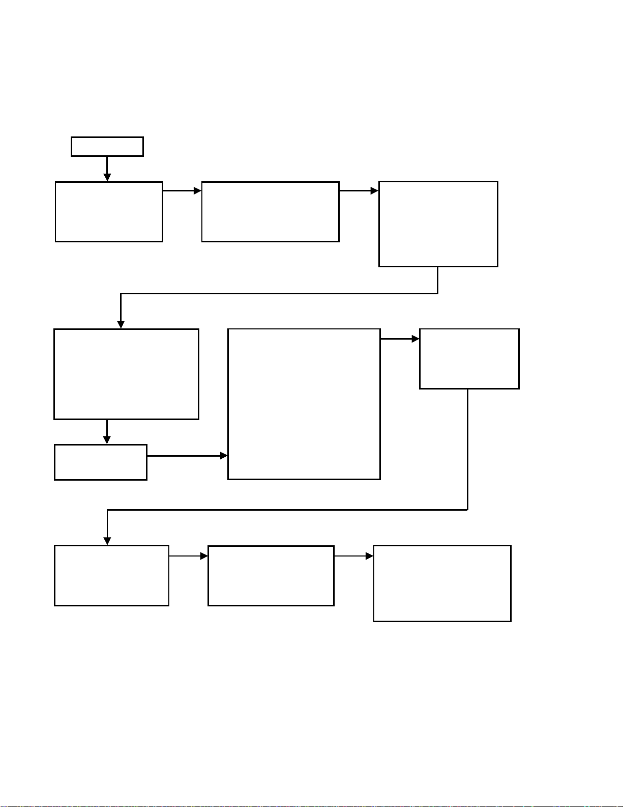
3. NORMAL ELECTRONIC CONTROL PROCESS FLOW OPERATION FOR FREEZER
POWER ON
Board Self Check
Display Read R##
(## is chip revision)
Frame heaters on
Cycle On (Cut-on
Temperature reached)
[Minimum 2.5 minutes]
1. Compressor start-up
2. Condenser Fan start-up
3. Evaporator Fan start-up
Continue as
Normal Cycling
2.5 minute delay
1. Compressor start-up
2. Condenser Fan start-up
3. Evaporator Fan start-up
Defrost Start
Preprogrammed time interval
1. Compressor off
2. Evaporator Fan off
3. Condenser Fan off
4. Defrost Heater on
5. “dEF” displayed
Cycle Off (Cut-out
Temperature reached)
[Minimum 2.5 minutes]
1. Compressor off
2. Condenser Fan off
3. Evaporator Fan off
Defrost end
defrost thermistor
reached 100°F
Defrost Heater off
Five minutes after
Defrost Heater off
1. Compressor on
2. Condenser Fan on
Note:
1) Cut-on / Cut-off / Cabinet Temperature are read by the same sensor, called “cabinet
thermistor.
2) Defrost Thermistor reads Evaporator temperature.
Evaporator temperature
reaches below 25°F
1. Evaporator Fan on
Cabinet temperature reads
a value below 15°F above
the setpoint.
“dEF” no longer displayed,
cabinet temp. displayed.
6
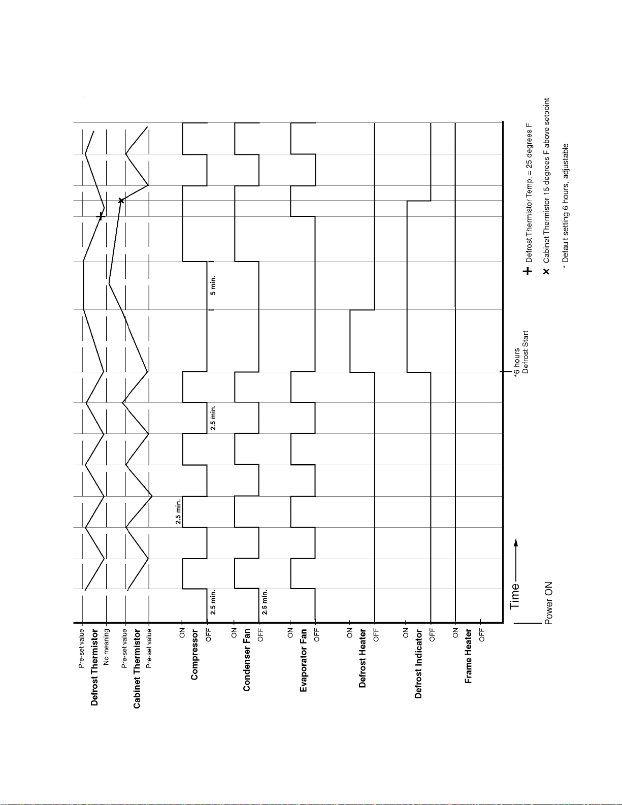
4. TIME - TEMPERATURE CONTROL CHART FOR FREEZER
7
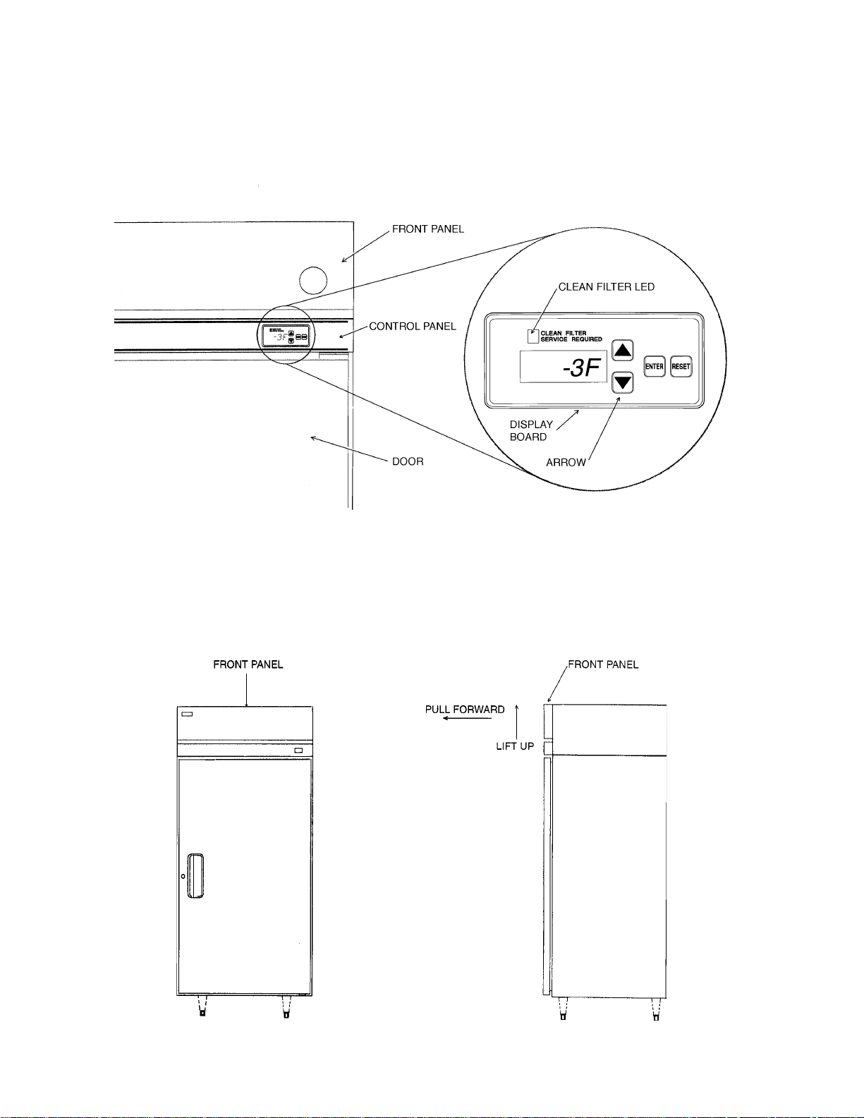
5. DISPLAY BOARD
The Display Board is located on the right hand side of the painted Control Panel between the top of
the Door and the Front Panel. From this area information regarding the functioning of the unit can be
obtained. From the Display Board various electronic controls and functions can also be adjusted.
Removing the Front Panel by lifting the panel up approximately one-half inch, then pulling it forward,
permits access to the Error Code Label, the Control Box and the Control Panel.
8

When unit is turned on, first display is “R##”, where “##” indicates chip revision level.
1) TEMPERATURE DISPLAY
• The cabinet temperature is displayed (factory set is °F, but can be changed to read °C).
• The cabinet temperature is updated every 20 seconds.
• During refrigerator defrost, the cabinet temperature is displayed.
• During freezer defrost, the cabinet temperature is not displayed, “dEF” is displayed in its
place.
2) GUARDED ACCESS MENU
Three settings can be viewed and changed from this menu:
1. The Temperature Setpoint. This setpoint is the value for the average cabinet
temperature.
2. Defrost Frequency.
Refrigerator: Automatic defrost. “df X” has no effect.
Freezer: Ex. “dF 4” = 4 defrost cycles per day.
3. Units of Display. F = Fahrenheit, C = Celsius
To enter this menu, press and hold the up/down arrows together for 3 seconds. The
Temperature Setpoint will be displayed first. To change a value, push the up/down arrows until
the desired value is displayed. Then push “ENTER” to set the value and view the next setting.
If no change in the value is desired, press “ENTER”, and the next setting will be displayed.
At the end of the sequence, press “ENTER” and the unit will return to normal display mode.
Note: End sequence and press “Enter” for changes to take effect. If sequence is
not ended by pressing “ENTER,” display will return to normal temperature
display and no changes will take effect.
9
6. ALARM / ALERT SIGNALS (*EXCLUDING GLASS DOOR MODELS)
ALARM
3 beeps
every ten
seconds
ERROR
MESSAGE
“E1” every 2
seconds,
alternating
with cabinet
temp. readout
PROBLEM
[FREEZERS WITH BOARD
REVISION LEVEL 10 OR
BELOW AND ALL
REFRIGERATORS]
Cabinet temp. has
exceeded set temp. by
10°F for more than 2
hours.
[FREEZERS WITH BOARD
REVISION LEVEL 11 AND
ABOVE]
Cabinet temp. has
exceeded set temp. by
25°F for more than 4
hours.
(FOR BOARD REVISION
LEVEL SEE “[1] NORMAL
ELECTRONIC CONTROL
PROCESS FLOW
OPERATION”)
RESET OPTIONS
Press “RESET.” If temp. has
returned to setpoint range, alarm
will stop and “E1” will clear.
If temp. is not back in range, “RESET” will silence the alarm for 5
minutes. “E1” will continue to flash.
4 beeps
every 10
seconds
[FREEZER
ONLY]
5 beeps
every 10
seconds
“E2” every 2
seconds,
alternating
with cabinet
temp. readout
“E3” every 2
seconds,
alternating
with “dEF” or
cabinet temp.
Cabinet temp. has
remained below setpoint
by 8°F for more than 1
hour.
Defrost has taken
longer than 1 hour.
Control Board has
terminated defrost.
Press “RESET.” If temp. has
returned to setpoint range, alarm
will stop and “E2” will clear.
If temp. is not back in range, “RESET” will silence the alarm for 5
minutes. “E2” will continue to flash.
Press “RESET.” Alarm will stop
and “E3” will clear.
If 4 consecutive defrosts take
more than 1 hour, a qualified
service technician must be
called.
For the Service Tech to reset this
alarm, press “RESET” on the
Control Board itself.
10
ALARM
ERROR MESSAGE
PROBLEM
RESET OPTIONS
6 beeps
every 10
seconds
8 beeps
every 10
seconds
9 beeps
every 10
seconds
“E4” every 2 seconds, alternating with
cabinet temp.
“E6” every 2 seconds,
alternating with
cabinet temp.
“E7” every 2 seconds, alternating with
cabinet temp.
Compressor discharge pressure is
outside normal operating range. Pressure
switch has been
triggered 3 or more
times in 1 hour.
Line voltage is too
high.
Line voltage is too
low.
Press “RESET.” If pressure switch
resets automatically, alarm will
stop and “E4” will clear when
pressure switch closes.
If switch trips 5 times in 1 hour
compressor will be stopped, and
not re-start. A service technician
must be called.
For the Service Tech to reset this
alarm, press “RESET” on the
Control Board itself.
Alarm automatically resets when
acceptable voltage is detected.
Press “RESET” to silence alarm for
5 minutes.
Alarm automatically resets when
acceptable voltage is detected.
Press “RESET” to silence alarm for
5 minutes.
1 beep
every 10
seconds
Continuous
buzzer
Continuous
buzzer
*2 beeps
every ten
seconds
“CF” every 2 seconds, alternating with
cabinet temp.;
“CLEAN FILTER”
LED lights.
“E8” every 2 seconds
“E9” every 2 seconds, alternating with
the cabinet temp.
*“door” every 2
seconds, alternating
with the cabinet temp.
Condenser filter
needs cleaning.
Cabinet temp. sensor
has failed.
Defrost temp. sensor
has failed.
*Display: Door open
Display and sound:
Door open longer than
3 minutes.
Clean filter. Allow time for sensor
to react, then press “RESET.”
During alarm, press “RESET” to
silence alarm for 2 hours.
If this alarm occurs frequently,
discharge temperature is consistently too high.
Replace sensor. Alarm will reset.
During alarm press “RESET” to
silence buzzer for 5 minutes.
Replace sensor. Alarm will reset.
During alarm press “RESET” to
silence buzzer for 5 minutes.
*Close door. During alarm, press
“RESET” to silence buzzer for 3
minutes.
11

ALARM
ERROR MESSAGE
PROBLEM
RESET OPTIONS
*10 beeps
every 10
seconds
*“E10” every 2 seconds, alternating with
cabinet temp.
*Freezer and Refrigerator boards not
communicating
properly to control
compressor delay
(RFH only).
*EXCLUDING GLASS DOOR MODELS
*When communication is restored,
alarm will reset.
*During alarm, press “RESET” to
silence buzzer for 18 hours.
12

a) HIGH TEMPERATURE ALARM FUNCTION
FOR FREEZERS WITH BOARD REVISION LEVEL 10 OR BELOW* AND FOR ALL REFRIGERATORS,
when c
OR FOR FREEZERS WITH BOARD REVISION LEVEL 11 AND ABOVE**, when cabinet temp. has
abinet temp. has exceeded set temp. by 10°F or more for more than 2 hours;
exceeded set temp. by 25°F or more for more than 4 hours,
an alarm buzzer sounds 3 beeps every 10 seconds, and an error message “E1” flashes
every 2 seconds, alternating with the cabinet temperature readout.
Reset Options:
If temperature has returned to setpoint range, pressing “RESET” on the Display Board will stop
the buzzer and clear the “E1” message.
If temperature is not back in range, pressing “RESET” on the display board will silence the
buzzer for 5 minutes. The “E1” message will continue to flash.
Note: Setting DIAGNOSTIC MENU item 3 to ON resets all alarms regardles of whether or not
setpoints are reached. This is a complete clearing of all alarms. See DIAGNOSTIC
MENU for details.
*FOR BOARD REVISION LEVEL SEE “[1] NORMAL ELECTRONIC CONTROL PROCESS FLOW
OPERATION”.
**UNLESS OTHERWISE NOTED.
b) LOW TEMPERATURE ALARM FUNCTION
When the cabinet temperature has been below the setpoint by 8°F for more than 1 hour, the
buzzer will sound 4 beeps every 10 seconds, and “E2” will flash every 2 seconds, alternating
with the cabinet temperature readout.
Reset Options:
If temperature has returned to setpoint range, pressing “RESET” on the Display Board will stop
the buzzer and clear the “E2” message.
If temperature is not back in range, pressing “RESET” on the Display Board will silence the
buzzer for 5 minutes. The “E2” message will continue to flash.
Note: Setting DIAGNOSTIC MENU item 3 to ON resets all alarms regardles of whether or not
setpoints are reached. This is a complete clearing of all alarms. See DIAGNOSTIC
MENU for details.
c) DEFROST ERROR ALERT FUNCTION [FREEZER ONLY]
If, for any reason, the defrost takes longer than 1 hour, the alarm buzzer will sound 5 beeps
every 10 seconds, and “E3” will flash every 2 seconds, alternating with either “dEF” or the
cabinet temperature. If this alarm activates, the Control Board will automatically terminate the
defrost.
Reset options:
Pressing “RESET” on the Display Board will reset the buzzer and clear the “E3” from the
display.
13
IMPORTANT
If 4 consecutive defrosts take more than 1 hour, pressing “RESET” on the Display Board will
only silence the buzzer until the next defrost that lasts more than 1 hour.
For the Service Tech to reset this alarm, press “RESET” on the Control Board itself.
d) HIGH PRESSURE ALERT FUNCTION
In order to protect the compressor if the discharge pressure reaches a preset value (outside the
normal operating range), a switch will temporarily stop the compressor. At another preset
pressure, the compressor will attempt to restart. If the switch is triggered 3 times in 1 hour, the
buzzer will sound 6 beeps every 10 seconds, and “E4” will flash every 2 seconds, alternating
with the cabinet temperature. The same sequence will occur if the switch trips the fourth time in
1 hour.
Reset Options:
During the third and fourth trip alarm, the buzzer can be silenced by pressing” RESET” on the
Display Board.
The buzzer and display will automatically reset when the pressure switch closes after the 3rd
and 4th reset.
After the 5th pressure trip, the buzzer can be silenced for 1 hour by pressing “RESET” on the
Display Board.
IMPORTANT
If the switch trips 5 times in 1 hour, the compressor will be stopped, and a service technician
must be called.
For the Service Tech to reset this alarm, press “RESET” on the Control Board itself.
e) HIGH VOLTAGE ALERT FUNCTION
When the unit detects the line voltage is above a preset value for 10 seconds, to protect the
compressor, the compressor will shut down. The buzzer will sound 8 beeps every 10 seconds.
“E6” will flash every 2 seconds, alternating with the cabinet temperature.
Reset Options:
This alarm automatically resets when an acceptable voltage is detected.
The buzzer can be silenced for 5 minutes while in alarm by pressing “RESET” on the Display
Board.
f) LOW VOLTAGE ALERT FUNCTION
When the unit detects the line voltage is below a preset value for 10 seconds, to protect the
compressor, the compressor will shut down. The buzzer will sound 9 beeps every 10 seconds.
“E7” will flash every 2 seconds, alternating with cabinet temperature.
14
 Loading...