

Hoshizaki America FD-1001MAH-C Installation Manual
Hoshizaki America, Inc.
Hoshizaki
Modular Flaker
Models
FD-1001MAH(-C)
“A Superior Degree
of Reliability”
www.hoshizaki.com
FD-1001MWH(-C)
FD-1001MRH(-C)
FD-1001MLH(-C)
INSTRUCTION MANUAL
Issued: 4-24-2009

IMPORTANT
Only qualied service technicians should install, service, and maintain the
icemaker. No installation, service, or maintenance should be undertaken
until the technician has thoroughly read this Instruction Manual. Likewise, the
owner/manager should not proceed to operate the icemaker until the installer
has instructed them on its proper operation. Failure to install, operate, and
maintain the equipment in accordance with this manual may adversely affect
safety, performance, compoent life, and warranty coverage.
Hoshizaki provides this manual primarily to assist qualied service technicians in the
installation, maintenance, and service of the icemaker.
Should the reader have any questions or concerns which have not been satisfactorily
addressed, please call, write, or send an e-mail message to the Hoshizaki Technical
Support Department for assistance.
HOSHIZAKI AMERICA, INC.
618 Highway 74 South
Peachtree City, GA 3069
Attn: Hoshizaki Technical Support Department
Phone: 1-800-33-1940 Technical Support
(770) 487-331
Fax: 1-800-843-1056
(770) 487-3360
E-mail: techsupport@hoshizaki.com
Web Site: www.hoshizaki.com
NOTE: To expedite assistance, all correspondence/communication MUST include the
following information:
• Model Number
• Serial Number
• Complete and detailed explanation of the problem.

IMPORTANT
This manual should be read carefully before the icemaker is installed and
operated. Only qualied service technicians should install, service, and
maintain the icemaker. Read the warnings contained in this booklet carefully as
they give important information regarding safety. Please retain this booklet for
any further reference that may be necessary.
CONTENTS
Important Safety Information ................................................................................................. 5
I. Specications ..................................................................................................................... 6
A. Nameplate Rating ......................................................................................................... 6
1. FD-1001MAH(-C) (air-cooled) ................................................................................. 6
. FD-1001MWH(-C) (water-cooled) ...........................................................................
3. FD-1001MRH(-C) (remote air-cooled) ..................................................................... 8
4. FD-1001MLH(-C) (low-side, parallel rack system) .................................................. 9
B. Dimensions / Connections .......................................................................................... 10
1. FD-1001MAH(-C) (air-cooled) ............................................................................... 10
. FD-1001MWH(-C) (water-cooled) ......................................................................... 11
3. FD-1001MRH(-C) (remote air-cooled) ................................................................... 1
4. FD-1001MLH(-C) (low side, parallel rack system) ................................................ 13
II. Installation and Operating Instructions ............................................................................ 14
A. Checks Before Installation .......................................................................................... 14
B. How to Remove Panels .............................................................................................. 14
C. Location ...................................................................................................................... 15
D. Setup .......................................................................................................................... 15
E. Electrical Connection .................................................................................................. 16
F. Installation of Remote Condenser Unit ....................................................................... 17
1. Checks Before Installation ..................................................................................... 17
. Location ................................................................................................................. 17
3. Setup ..................................................................................................................... 18
4. Line Set ................................................................................................................. 18
5. Electrical Connection ............................................................................................. 1
6. Stacking Remote Condenser Units .......................................................................
G. Connection to an R-404A Parallel Rack System ........................................................ 3
1. Line Set Installation ............................................................................................... 3
H. Water Supply and Drain Connections......................................................................... 6
1. Icemaker ................................................................................................................ 7
. Water-Cooled Condenser ...................................................................................... 8
I. Final Checklist ............................................................................................................. 30
J. Startup ......................................................................................................................... 31
K. Bin Control Check ....................................................................................................... 3
1. Infrared Sensor Check .......................................................................................... 3
. Mechanical Backup Bin Control Check ................................................................. 34
3. Infrared Sensor Shutdown Delay .......................................................................... 35
7
3

III. Cleaning and Maintenance ............................................................................................. 36
A. Cleaning and Sanitizing Instructions ........................................................................... 36
1. Cleaning Solution .................................................................................................. 36
. Cleaning Procedure ............................................................................................... 36
3. Sanitizing Solution ................................................................................................. 39
4. Sanitizing Procedure - Initial .................................................................................. 39
5. Sanitizing Procedure - Final .................................................................................. 40
B. Maintenance ............................................................................................................... 41
C. Preparing the Icemaker for Long Storage .................................................................. 4
4
Important Safety Information
Throughout this manual, notices appear to bring your attention to situations which could
result in death, serious injury, or damage to the unit.
WARNING Indicates a hazardous situation which could result in death or
serious injury.
CAUTION Indicates a situation which could result in damage to the unit.
IMPORTANT Indicates important information about the use and care of the
unit.
WARNING
This icemaker should be destined only to the use for which it has been
expressly conceived. Any other use should be considered improper and
therefore dangerous. The manufacturer cannot be held responsible for
eventual damage caused by improper, incorrect, and unreasonable use.
To reduce the risk of death, electric shock, serious injury, or re, follow
basic precautions including the following:
• Electrical connection must be hard-wired and must meet national, state, and
local electrical code requirements. Failure to meet these code requirements
could result in death, electric shock, serious injury, re, or severe damage to
equipment.
• This unit requires an independent power supply. See the nameplate for
proper voltage and breaker/fuse size. Failure to use a proper breaker or fuse
can result in a tripped breaker, blown fuse, or damage to existing wiring. This
could lead to heat generation or re.
• THIS UNIT MUST BE GROUNDED. Failure to properly ground this unit could
result in death or serious injury.
• This unit should be disassembled or repaired only by qualied service
personnel to reduce the risk of electric shock, injury, or re.
• Do not make any alterations to the unit. Alterations could result in electric
shock, injury, re, or damage to the unit.
5
I. Specications
HOSHIZAKI ICE MAKER
MOTOR-COMPRESSOR THERMALLY PROTECTED,
NOT INTENDED FOR OUTDOOR USE!
Hoshizaki America, Inc.
Peachtree City, GA
www.hoshizaki.com
ICE MAKER WITHOUT
STORAGE MEANS
946Z
COMPONENT
186090
A. Nameplate Rating
1. FD-1001MAH(-C) (air-cooled)
MODEL NUMBER FD-1001MAH
SERIAL NUMBER
AC SUPPLY VOLTAGE
COMPRESSOR 240V 4.2RLA 34LRA
GEAR MOTOR 120V 3.0FLA 1/4HP
FAN MOTOR 115V 0.85FLA 1/15HP
OTHER 120V 0.03A
MAXIMUM FUSE SIZE 15 AMPS
MAX HACR BREAKER (USA ONLY) 15 AMPS
MAX CIRC BREAKER (CANADA ONLY) 15 AMPS
MINIMUM CIRCUIT AMPACITY 15 AMPS
DESIGN PRESSURE HI-427PSI LO-230PSI
REFRIGERANT 404A 1 LB 12 OZ.
208-230/60/1 (3 WIRE
WITH NEUTRAL FOR
115V)
Note: Only the "MODEL NUMBER" is replaced for FD-1001MAH-C.
See the nameplate for electrical and refrigeration specications. This nameplate is located
on the rear panel.
Since this nameplate is located on the rear panel of the icemaker, it cannot be read when
the back of the icemaker is against a wall or against another piece of kitchen equipment.
Therefore, the necessary electrical and refrigeration information is also on the rating label,
which can be easily seen by removing only the front panel of the icemaker.
We reserve the right to make changes in specications and design without prior notice.
6
2. FD-1001MWH(-C) (water-cooled)
HOSHIZAKI ICE MAKER
MOTOR-COMPRESSOR THERMALLY PROTECTED,
NOT INTENDED FOR OUTDOOR USE!
Hoshizaki America, Inc.
Peachtree City, GA
www.hoshizaki.com
ICE MAKER WITHOUT
STORAGE MEANS
946Z
COMPONENT
186090
MODEL NUMBER FD-1001MWH
SERIAL NUMBER
AC SUPPLY VOLTAGE
COMPRESSOR 240V 4.2RLA 34LRA
GEAR MOTOR 120V 3.0FLA 1/4HP
FAN MOTOR --- --- --OTHER 120V 0.03A
MAXIMUM FUSE SIZE 15 AMPS
MAX HACR BREAKER (USA ONLY) 15 AMPS
MAX CIRC BREAKER (CANADA ONLY) 15 AMPS
MINIMUM CIRCUIT AMPACITY 15 AMPS
DESIGN PRESSURE HI-427PSI LO-230PSI
REFRIGERANT 404A 1 LB 1 OZ.
208-230/60/1 (3 WIRE
WITH NEUTRAL FOR
115V)
Note: Only the "MODEL NUMBER" is replaced for FD-1001MWH-C.
See the nameplate for electrical and refrigeration specications. This nameplate is located
on the rear panel.
Since this nameplate is located on the rear panel of the icemaker, it cannot be read when
the back of the icemaker is against a wall or against another piece of kitchen equipment.
Therefore, the necessary electrical and refrigeration information is also on the rating label,
which can be easily seen by removing only the front panel of the icemaker.
We reserve the right to make changes in specications and design without prior notice.
7
HOSHIZAKI ICE MAKER
3. FD-1001MRH(-C) (remote air-cooled)
MOTOR-COMPRESSOR THERMALLY PROTECTED,
NOT INTENDED FOR OUTDOOR USE!
Hoshizaki America, Inc.
Peachtree City, GA
www.hoshizaki.com
ICE MAKER WITHOUT
STORAGE MEANS
946Z
COMPONENT
186090
MODEL NUMBER FD-1001MRH
SERIAL NUMBER
AC SUPPLY VOLTAGE
COMPRESSOR 240V 4.2RLA 34LRA
GEAR MOTOR 120V 3.0FLA 1/4HP
FAN MOTOR REMOTE 120V 3A MAX
OTHER 120V 0.53A
MAXIMUM FUSE SIZE 15 AMPS
MAX HACR BREAKER (USA ONLY) 15 AMPS
MAX CIRC BREAKER (CANADA ONLY) 15 AMPS
MINIMUM CIRCUIT AMPACITY 15 AMPS
DESIGN PRESSURE HI-427PSI LO-230PSI
REFRIGERANT 404A
208-230/60/1 (3 WIRE
WITH NEUTRAL FOR
115V)
Note: Only the "MODEL NUMBER" is replaced for FD-1001MRH-C.
See the nameplate for electrical and refrigeration specications. This nameplate is located
on the rear panel.
Since this nameplate is located on the rear panel of the icemaker, it cannot be read when
the back of the icemaker is against a wall or against another piece of kitchen equipment.
Therefore, the necessary electrical and refrigeration information is also on the rating label,
which can be easily seen by removing only the front panel of the icemaker.
We reserve the right to make changes in specications and design without prior notice.
8
4. FD-1001MLH(-C) (low-side, parallel rack system)
HOSHIZAKI ICE MAKER
MOTOR-COMPRESSOR THERMALLY PROTECTED,
NOT INTENDED FOR OUTDOOR USE!
Hoshizaki America, Inc.
Peachtree City, GA
www.hoshizaki.com
ICE MAKER WITHOUT
STORAGE MEANS
946Z
COMPONENT
186090
MODEL NUMBER FD-1001MLH
SERIAL NUMBER
AC SUPPLY VOLTAGE 115-120/60/1
COMPRESSOR --- --- --GEAR MOTOR 120V 3.0FLA 1/4HP
FAN MOTOR --- --- --OTHER 120V 0.53A
MAXIMUM FUSE SIZE 15 AMPS
MAX. HACR BREAKER (USA ONLY) 15 AMPS
MAX. CIRC. BREAKER (CANADA ONLY) 15 AMPS
MINIMUM CIRCUIT AMPACITY 15 AMPS
DESIGN PRESSURE HI-427PSI LO-230PSI
REFRIGERANT 404A
Note: Only the "MODEL NUMBER" is replaced for FD-1001MLH-C.
See the nameplate for electrical and refrigeration specications. This nameplate is located
on the rear panel.
Since this nameplate is located on the rear panel of the icemaker, it cannot be read when
the back of the icemaker is against a wall or against another piece of kitchen equipment.
Therefore, the necessary electrical and refrigeration information is also on the rating label,
which can be easily seen by removing only the front panel of the icemaker.
We reserve the right to make changes in specications and design without prior notice.
9
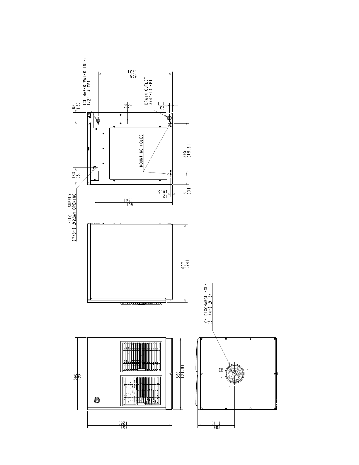
B. Dimensions / Connections
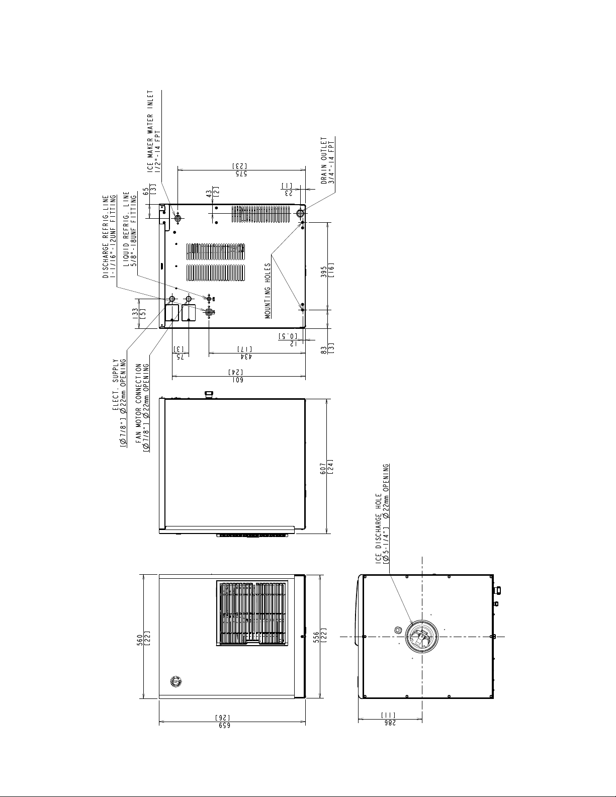
1. FD-1001MAH(-C) (air-cooled)
Unit = mm [in.]
10
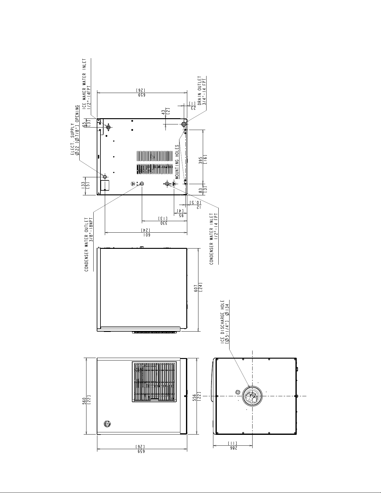
2. FD-1001MWH(-C) (water-cooled)
Unit = mm [in.]
11
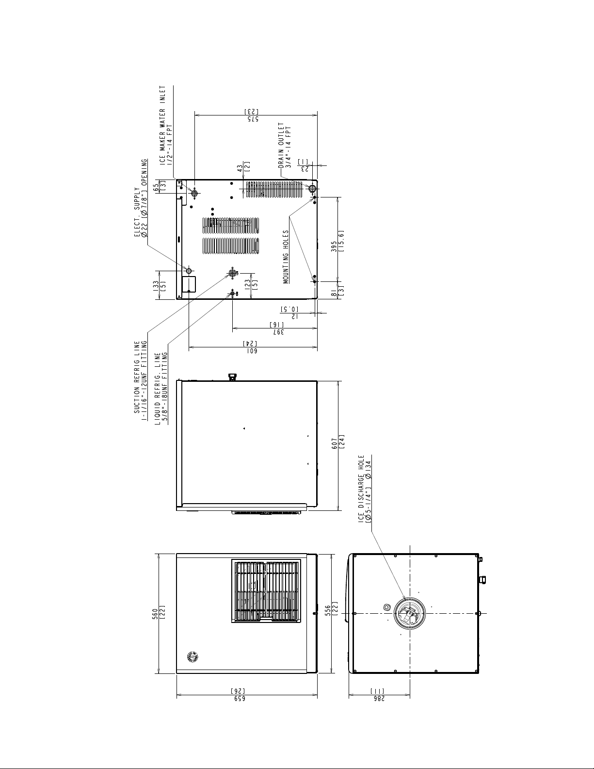
3. FD-1001MRH(-C) (remote air-cooled)
Unit = mm [in.]
1
4. FD-1001MLH(-C) (low side, parallel rack system)
Unit = mm [in.]
13
II. Installation and Operating Instructions
WARNING
1. This icemaker must be installed in accordance with all applicable national,
state, and local regulations.
. CHOKING HAZARD: Ensure all components, fasteners, and thumbscrews
are securely in place after installation. Make sure that none have fallen into
the dispenser unit/storage bin.
A. Checks Before Installation
• Visually inspect the exterior of the shipping container and immediately report any
damage to the carrier. Upon opening the container, any concealed damage should also
be immediately reported to the carrier.
• Remove the shipping carton, tape, and packing material. If any are left in the icemaker,
it will not work properly.
• Remove the panels to prevent damage when installing the icemaker. See "II.B. How to
Remove Panels."
• Remove the package containing the accessories.
• Remove the protective plastic lm from the panels. If the icemaker is exposed to the
sun or to heat, remove the lm after the icemaker cools.
• Check that the refrigerant lines do not rub or touch lines or other surfaces, and that the
fan blade (if applicable) turns freely.
• Check that the compressor is snug on all mounting pads.
• See the nameplate on the rear panel, and check that your voltage supplied
corresponds with the voltage specied on the nameplate.
• Flaker models can be installed on a storage bin " wide or wider. Cubelet models can
be installed on either a dispenser unit or a storage bin " wide or wider.
• If using a storage bin, Hoshizaki Ice Storage Bin, Model B-300 series is recommended.
For further options, contact your local Hoshizaki distributor.
• On remote air-cooled model, a remote condenser unit is needed. Hoshizaki Remote
Condenser Unit, Model URC-5F is recommended.
• On low-side models, an R-404A parallel rack system is needed. See "II.G. Connection
to an R-404A Parallel Rack System" for refrigeration circuit details.
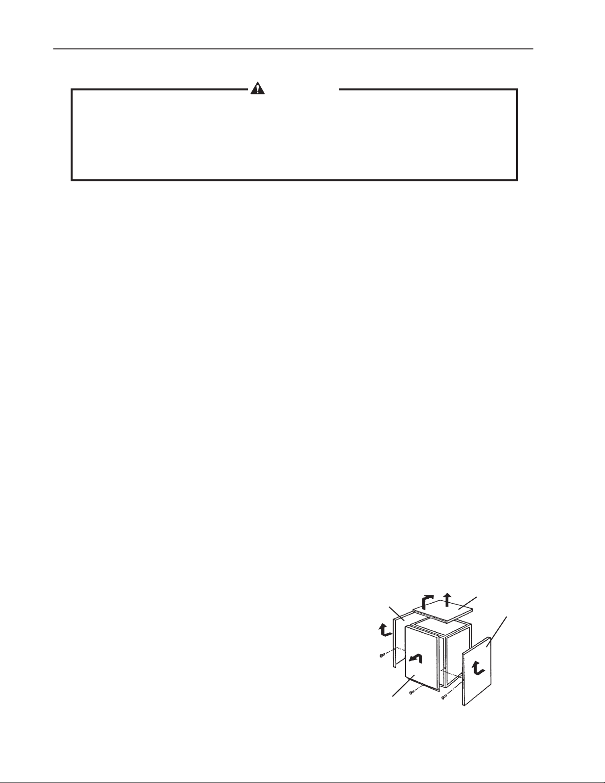
Side Panel
B. How to Remove Panels
See Fig. 1
Top Panel
Side Panel
• Front Panel: Remove the screw. Lift up and towards
you.
• Top Panel: Lift up at the front slightly, push rearward,
and lift off.
• Side Panels: Remove the screw. Slide forward
slightly and lift off.
14
Front Panel
Fig. 1
 Loading...