

Page 1

NO:
ISSUED:
REVISED:
73116
JULY 16, 2004
AUG. 20, 2004
HOSHIZAKI
MODULAR FLAKER
MODEL
F-2000MWH/-C
F-2000MRH/-C
F-2000MRH3/-C
F-2000MLH/-C
SERVICE MANUAL
Page 2

IMPORTANT
Only qualified service technicians should attempt to service or maintain this icemaker.
No such service or maintenance should be undertaken until the technician has
thoroughly read this Service Manual.
HOSHIZAKI provides this manual primarily to assist qualified service technicians in the service
and maintenance of the icemaker.
Should the reader have any questions or concerns which have not been satisfactorily
addressed, please call or write to the HOSHIZAKI Technical Support Department for
assistance.
HOSHIZAKI AMERICA, INC.
618 Highway 74 South
Peachtree City, GA 30269
Attn: HOSHIZAKI Technical Support Department
Phone: 1-800-233-1940 Technical Service
(770) 487-2331
Fax: (770) 487-3360
NOTE: To expedite assistance, all correspondence/communication MUST include the following
information:
• Model Number
• Serial Number
• Complete and detailed explanation of the problem
2
Page 3

Please review this manual. It should be read carefully before the icemaker is serviced or
maintenance operations are performed. Only qualified service technicians should service and
maintain the icemaker. This manual should be made available to the technician prior to
service or maintenance.
I. SPECIFICATION ............................................................................................................... 5
1. ICEMAKER................................................................................................................... 5
F-2000MWH ............................................................................................................... 5
F-2000MWH-C ........................................................................................................... 6
F-2000MRH ................................................................................................................ 7
F-2000MRH-C ............................................................................................................ 8
F-2000MRH3 .............................................................................................................. 9
F-2000MRH3-C ........................................................................................................ 10
F-2000MLH .............................................................................................................. 11
F-2000MLH-C .......................................................................................................... 12
2. CONDENSER UNIT .................................................................................................... 13
URC-20F .................................................................................................................. 13
II. GENERAL INFORMATION .............................................................................................. 15
1. CONSTRUCTION ....................................................................................................... 15
F-2000MWH/-C ........................................................................................................ 15
F-2000MRH/-C, F-2000MRH3/-C ............................................................................. 16
F-2000MLH/-C.......................................................................................................... 17
2. CONTROL BOX LAYOUT............................................................................................ 18
F-2000MWH/-C, F-2000MRH/-C .............................................................................. 18
F-2000MRH3/-C ....................................................................................................... 19
F-2000MLH/-C.......................................................................................................... 20
III. TECHNICAL INFORMATION .......................................................................................... 21
1. WATER CIRCUIT AND REFRIGERATION CIRCUIT ..................................................... 21
F-2000MWH/-C ........................................................................................................ 21
F-2000MRH/-C, F-2000MRH3/-C ............................................................................. 22
F-2000MLH/-C.......................................................................................................... 23
2. WIRING DIAGRAMS ................................................................................................... 24
F-2000MWH/-C ........................................................................................................ 24
F-2000MRH/-C ......................................................................................................... 25
F-2000MRH3/-C ....................................................................................................... 26
F-2000MLH/-C.......................................................................................................... 27
3. SEQUENCE OF ELECTRICAL CIRCUIT .................................................................... 28
4. TIMING CHART ........................................................................................................... 36
5. PERFORMANCE DATA ............................................................................................. 41
F-2000MWH ............................................................................................................. 41
F-2000MWH-C ......................................................................................................... 42
F-2000MRH .............................................................................................................. 43
F-2000MRH-C .......................................................................................................... 44
F-2000MRH3 ............................................................................................................ 45
F-2000MRH3-C ........................................................................................................ 46
F-2000MLH .............................................................................................................. 47
F-2000MLH-C .......................................................................................................... 48
CONTENTS
3
Page 4

IV. ADJUSTMENT OF COMPONENTS ............................................................................... 49
1. ADJUSTMENT OF WATER REGULATING VALVE - WATER-COOLED MODEL ONLY49
2. ADJUSTMENT OF FLAKE SIZE ................................................................................. 50
3. ADJUSTMENT OF EVAPORATOR PRESSURE REGULATOR (E.P.R) -
F-2000MLH/-C ONLY ................................................................................................. 51
V. SERVICE DIAGNOSIS .................................................................................................. 52
1. NO ICE PRODUCTION ............................................................................................... 52
2. LOW ICE PRODUCTION ............................................................................................ 55
3. OTHERS ..................................................................................................................... 56
VI. REMOVAL AND REPLACEMENT OF COMPONENTS ................................................ 57
1. SERVICE FOR REFRIGERANT LINES ...................................................................... 57
[a] REFRIGERANT RECOVERY [EXCEPT F-2000MLH/-C] ..................................... 57
[b] REFRIGERANT RECOVERY [F-2000MLH/-C ONLY] ........................................... 57
[c] EVACUATION AND RECHARGE [R-404A] .......................................................... 57
2. BRAZING .................................................................................................................... 59
3. REMOVAL AND REPLACEMENT OF COMPRESSOR - EXCEPT F-2000MLH/-C .... 60
4. REMOVAL AND REPLACEMENT OF DRIER - EXCEPT F-2000MLH/-C .................. 61
5. REMOVAL AND REPLACEMENT OF EXPANSION VALVE ...................................... 62
6. REMOVAL AND REPLACEMENT OF WATER REGULATING VALVE -
WATER-COOLED MODELS ONLY. ........................................................................... 63
7. REMOVAL AND REPLACEMENT OF CONDENSING PRESSURE
REGULATOR (C.P.R.) - REMOTE AIR-COOLED MODELS ONLY.............................. 64
8. REMOVAL AND REPLACEMENT OF EVAPORATOR ASSEMBLY ........................... 65
9. REMOVAL AND REPLACEMENT OF FAN MOTOR................................................... 69
10. REMOVAL AND REPLACEMENT OF CONTROL WATER VALVE .......................... 69
11. REMOVAL AND REPLACEMENT OF FLUSH WATER VALVE ................................ 70
12. REMOVAL AND REPLACEMENT OF SOLENOID VALVE - F-2000MLH/-C ONLY ... 71
13. REMOVAL AND REPLACEMENT OF EVAPORATOR PRESSURE
REGULATOR (E.P.R.) - F-2000MLH/-C ONLY .......................................................... 72
14. REMOVAL AND REPLACEMENT OF BY-PASS VALVE -
F-2000M_H/-C SERIES ONLY [EXCEPT F-2000MLH/-C] ........................................ 73
VII. CLEANING AND MAINTENANCE INSTRUCTIONS ...................................................... 75
1. PREPARING THE ICEMAKER FOR LONG STORAGE .............................................. 75
[Remote Air-cooled Models] ...................................................................................... 75
[Water-cooled Models] .............................................................................................. 76
2. CLEANING INSTRUCTIONS ....................................................................................... 76
3. MAINTENANCE INSTRUCTIONS ............................................................................... 80
4
Page 5
I. SPECIFICATION
1. ICEMAKER
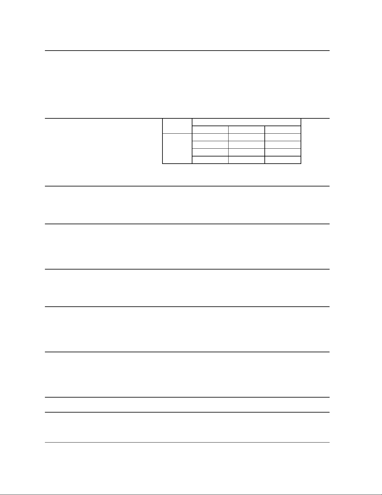
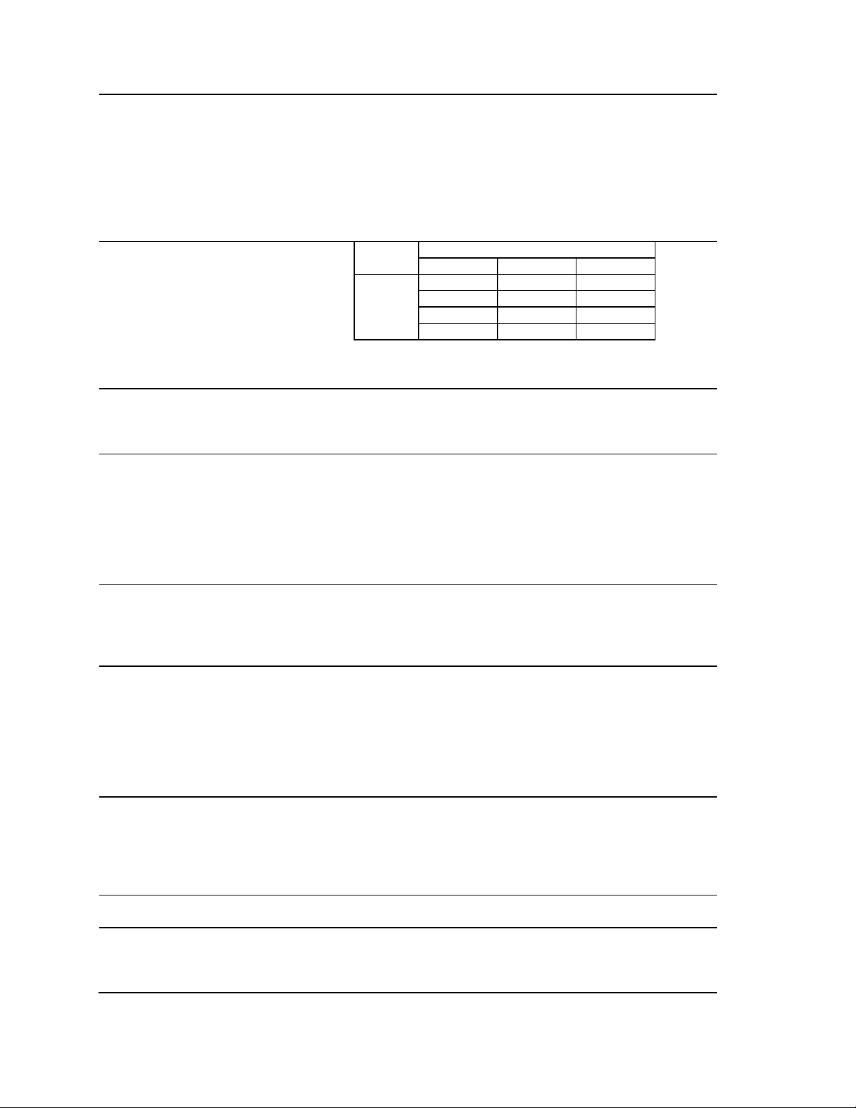
F-2000MWH
AC SUPPLY VOLTAGE 208-230/60/1 (3 wire with neutral for 115V)
COMPRESSOR 240 V 10.8 RLA 96 LRA
GEAR MOTOR 120 V 5.6 FLA 0.54 HP
FAN MOTOR 120 V 0.51 FLA 8W
OTHER 120 V 0.03A
MAXIMUM FUSE SIZE 30 A
MAX. HACR BREAKER (USA ONLY) 30 A
MAX. CIRC. BREAKER (CANADA ONLY) 30 A
MINIMUM CIRCUIT AMP ACITY 30 A
APPROXIMATE ICE PRODUCTION Ambient WATER TEMP. (°F)
PER 24 HR. Temp.(°F) 50 70 90
lbs./day ( kg/day ) 70 *2030 (921) 1955 (887) 1915 (869)
Reference without *marks 80 1875 (851) 1835 (832) 1795 (814)
90 1760 (798) *1730 (785) 1685 (764)
100 1650 (748) 1615 (733) *1500 (680)
SHAPE OF ICE Flake
ICE QUALITY Approx . 70%, Ice (90/70°F, Conductivity 200 µs/cm)
APPROXIMATE STORAGE CAPACITY N/A
ELECTRIC & WATER CONSUMPTION 90/70°F 70/50°F
ELECTRIC W (kWH/100 lbs.) 2510 (3.5) 2490 (2.9)
POTABLE WATER 207 (12) 243 (12)
WATER-COOLED CONDENSER 1165 (67) 735 (36)
gal./24HR (gal./100 lbs.)
EXTERIOR DIMENSIONS (WxDxH) 30" x 27-1/2" x 34-7/16" (762 x 699 x 874mm)
EXTERIOR FINISH Stainless Steel, Galvanized Steel (Rear)
WEIGHT Net 310 lbs. ( 140 kg ), Shipping 342 lbs. ( 155 kg )
CONNECTIONS - ELECTRIC Permanent - Connection
- WATER SUPPLY Inlet 1/2" FPT Cond. Inlet 1/2" FPT
- DRAIN Outlet 3/4" FPT Cond. Outlet 1/2" FPT
ICE MAKING SYSTEM Auger type
HARV ESTING SYSTEM Direc t Driven Auger ( 400 W Gear Motor )
ICE MAK ING W ATER CONTROL Float Switch
COOLING WATER CONTROL Automatic W at er Regulator
BIN CONTROL SYSTEM Mechanical Bin Control ( Proximity Sw. )
COMPRESSOR Hermetic, Model CS20-K6E-PFV
CONDENSER Water-cooled, Tube in tube type
EVAPORATOR Copper Tube on Cylinder
REFRIGERANT CONTROL Thermos tatic E xpans ion Valve
REFRIGERANT CHARGE R-404A, 2 lbs. (910g)
DESIGN PRESSURE High 460 PSIG, Low 290 PSIG
P. C. BOARD CIRCUIT PROTECTION High Voltage Cut-off Relay
COMPRESSOR PROTECTION Internal Protector
GEAR MOTOR PROTECTION Manual Reset Circuit Breaker & Thermal Protector
REFRIGERANT CIRCUIT PROTECTION Auto-reset High Pres s ure Control Switch
LOW WATER PROTECTION Float Swit ch and Timer
BIN CONTROL P ROTECTION Manual Reset S pout Control
ACCESSORIES -SUPPLIED Spare Fuse
-REQUIRED Ice Storage Bin
OPERATING CONDITIONS VOLTAGE RANGE 187-253 V
AMBIENT TEMP. 45-100° F
WATER SUPPLY TEMP. 45-90° F
WATER SUPPLY PRESSURE 10-113 PSIG
We reserve the right to make changes in specifications and design without prior notice.
5
Page 6
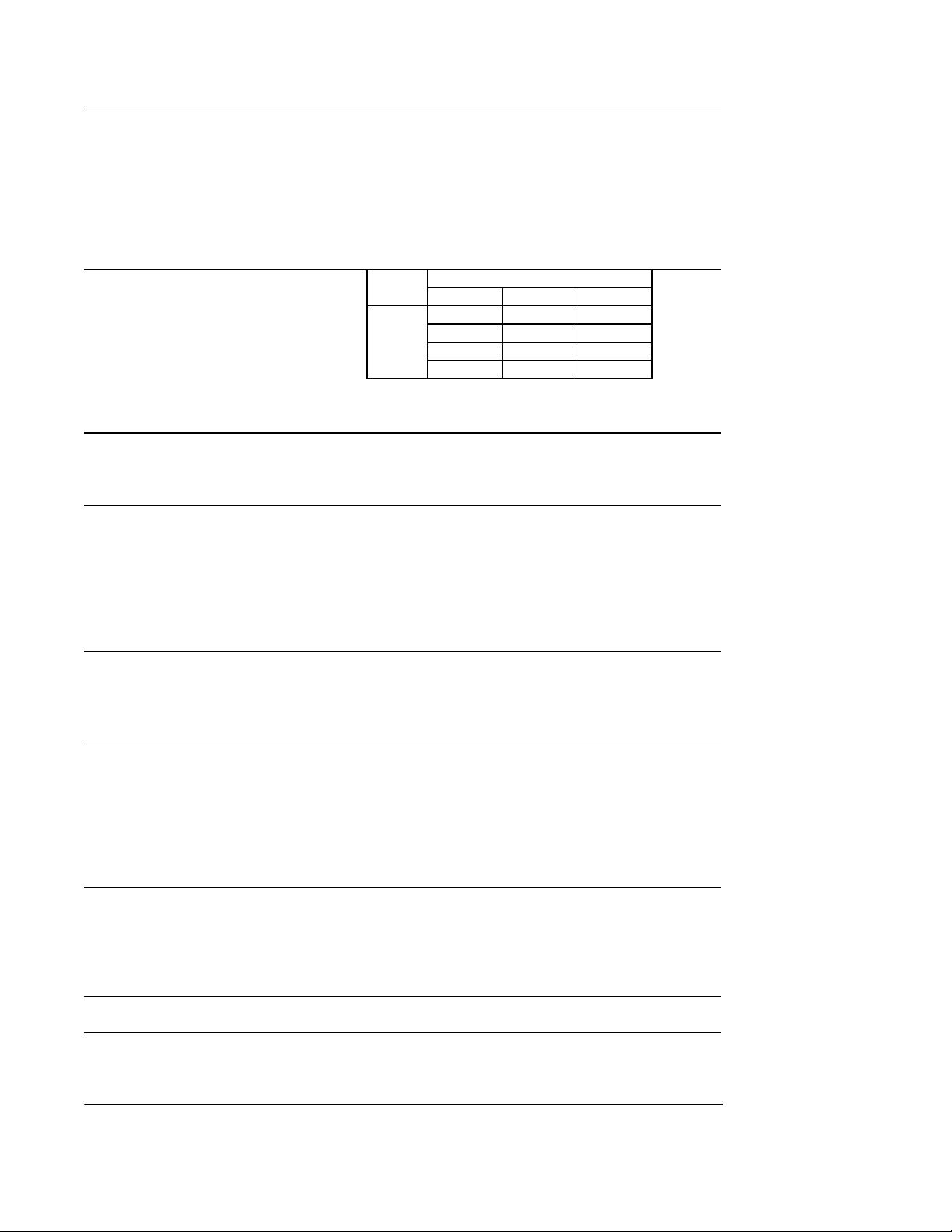
F-2000MWH-C
L
)
Y
N
N
AC SUPPLY VOLTAGE 208-230/60/1 (3 wire wit h neutral for 115V)
COMPRESSOR 240 V 10.8 RLA 96 LRA
GEAR MOTOR 120 V 5.6 FLA 0.54 HP
FAN MOTOR 120 V 0.51 FLA 8W
OTHER 120 V 0.03A
MAXIMUM FUSE SIZE 30 A
MAX. HACR BREAKER (USA ONLY) 30 A
MAX. CIRC. BREAKER (CANADA ON
MINIMUM CIRCUIT AMPA CITY 30 A
APPROXIMATE ICE PRODUCTION Ambient WATER TEMP. (°F)
PER 24 HR. Temp.(°F
lbs./day ( k g/day ) 70 *1790 (812) 1725 (782) 1700 (771)
Reference without *marks 80 1670 (757) 1640 (744) 1615 (733)
SHAPE OF ICE Cubelet
ICE QUALITY Approx.80%, Ice (90/70°F, Conductivity 200 µs/cm)
APPROXIMATE STORAGE CAPACIT
ELECTRIC & WATER CONSUMPTIO
ELECTRIC W (kWH/100 lbs.) 2585 (4.0) 2555 (3.4)
POTABLE WATER 185 (12) 215 (12)
WATER-COOLED CONDENSER 1190 (76) 765 (43)
gal./24HR (gal./100 lbs.)
EXTERIOR DIMENSIONS (WxDxH) 30" x 27-1/2" x 34-7/16" (762 x 699 x 874mm)
EXTERIOR FINISH Stainless Steel, Galvanized Steel (Rear)
WEIGHT Net 310 lbs. ( 140 kg ), Shipping 342 lbs. ( 155 kg )
CONNECTIONS - ELECTRIC Permanent - Connection
- WATER SUPPLY Inlet 1/2" FPT Cond. Inlet 1/2" FPT
- DRAIN Outlet 3/4" FPT Cond. Outlet 1/2" FPT
ICE MAKING SYSTEM Auger type
HARVESTING SYSTEM Direct Driven Auger ( 400 W Gear Motor )
ICE MAKING WATER CONTROL Float Switch
COOLING WATER CONTROL Automatic W ater Regulator
BIN CONTROL SYSTEM Mechanical Bin Control ( Proximity Sw. )
COMPRESSOR Hermetic, Model CS20-K6E-PFV
CONDENSER Water-cooled, Tube in tube type
EVAPORATOR Copper Tube on Cylinder
REFRIGERANT CONTROL Thermostatic Expansion Valve
REFRIGERANT CHARGE R-404A, 2 lbs. (910g)
DESIGN PRESSURE High 460 PSIG, Low 290 PSIG
P.C. BOARD CIRCUIT PROTECTION High Voltage Cut-off Relay
COMPRESSOR PROTECTION Internal Protector
GEAR MOTOR PROTECTION Manual Reset Circuit Breaker & Thermal Protector
REFRIGE RANT CIRCUIT PROTECTIO
LOW WATER PROTECTION Float Switch and Timer
BIN CONTROL PROTECTION Manual Reset Spout Control
ACCESSORIES -SUPPLIED Spare Fuse
-REQUIRED Ice Storage Bin
OPERATING CONDITIONS VOLTAGE RANGE 187-253 V
We reserve the right to make changes in specifications and design without prior notice.
30 A
50 70 90
90 1585 (719) *1560 (708) 1535 (696)
100 1510 (685) 1485 (674) *1375 (624)
N/A
90/70°F 70/50°F
Auto-reset High Pressure Control Switch
AMBIENT TEMP. 45-100° F
WATER SUPPLY TEMP. 45-90° F
WATER SUPPLY PRESSURE 10-113 PSIG
6
Page 7
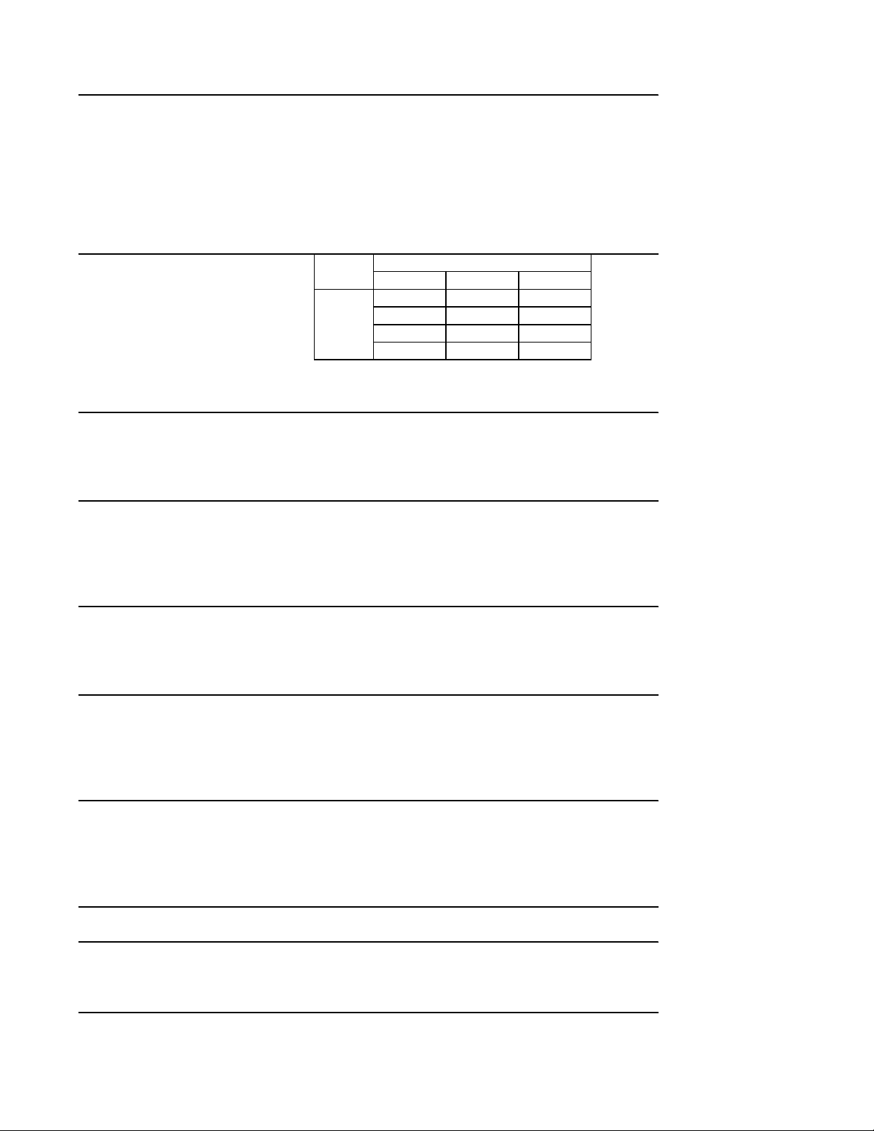
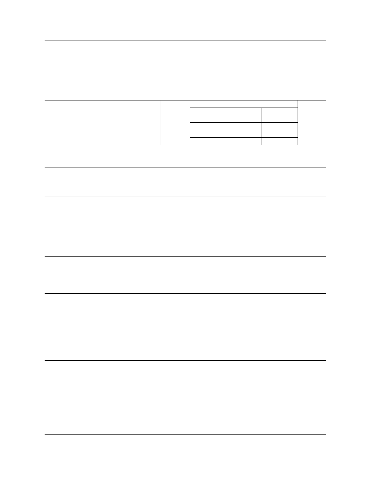
F-2000MRH
AC SUPPLY VOLTAGE 208-230/60/1 (3 wire with neutral for 115V)
COMPRESSOR 240 V 10.8 RLA 96 LRA
GEAR MOTOR 120 V 5.6 FLA 0.54 HP
FAN MOTOR REMOTE 120 V 3A MAX
OTHER 120 V 0.03A
MAXIMUM FUSE SIZE 30 A
MAX. HACR BREAKER (USA ONLY) 30 A
MAX. CIRC. BREAKER (CANADA ONLY) 30 A
MINIMUM CIRCUIT AMPACITY 30 A
APPROXIMATE ICE PRODUCTION Ambient WATER TEMP. (°F)
PER 24 HR. Temp.(°F)507090
lbs./day ( k g/day ) 70 *1990 (902) 1930 (875) 1880 (853)
Reference without *marks 80 1825 (828) 1775 (805) 1730 (785)
90 1685 (764) *1675 (760) 1595 (723)
100 1550 (703) 1510 (685) *1395 (633)
SHAPE OF ICE Flake
ICE QUALITY Approx. 70%, Ice (90/70°F, Conduc tivity 200 µs/c m)
APPROXIMATE STORAGE CAPACITY N/A
ELECTRIC & W ATER CONS UMP TION 90/70°F 70/50°F
ELECTRIC W (kWH/100 lbs.) 2785 (4.0) 2770 (3.3)
POTABLE WATER 201 (12) 239 (12)
gal./24HR (gal./100 lbs.)
EXTERIOR DIMENSIONS (W x DxH) 30" x 27-1/2" x 34-7/16" (762 x 699 x 874mm)
EXTERIOR FINISH Stainless Steel, Galvanized Steel (Rear)
WEIGHT Net 310 lbs. ( 140 kg ), Shipping 342 lbs. ( 155 kg )
CONNECTIONS - ELECTRIC Permanent - Connect ion
- WATER SUPPLY Inlet 1/2" FPT
- DRAIN Outlet 3/4" FPT
- REFRIGERATION Discharge line 1-1/16-12 UNF Fitting (#10 AEROQUIP)
CIRCUIT Liquid line 5/8-18 UNF Fitting (#6 AEROQUIP)
ICE MAKING SYSTEM Auger type
HARVESTING SYSTEM Direct Driven Auger ( 400 W Gear Motor )
ICE MAK ING W ATER CONTROL Float Switch
COOLING W A TER CONTROL N/A
BIN CONTROL SYSTEM Mechanical Bin Control ( Proximity Sw. )
COMPRESSOR Hermetic, Model CS20-K6E-PFV
CONDENSER Air-cooled Remot e Condenser unit URC-20F Rec ommended
EVAPORATOR Copper Tube on Cylinder
REFRIGERA NT CONTROL Thermostatic Ex pansi on Valve
Condens ing Pressure Regulator on URC-20F
REFRIGERA NT CHARGE R-404A, 14 lb. 9 oz. (6600g)
(Ice Maker: 6 lb. 14 oz., Cond. Unit: 7 lb. 11 oz. )
DESIGN PRESSURE High 460 PSIG, Low 290 PSIG
P.C. BOARD CIRCUIT PROTECTION High Voltage Cut -off Relay
COMPRESSOR PROTECTION Internal Protector
GEAR MOTOR PROTECTION Manual Reset Circuit Breaker & Thermal Protector
REFRIGERA NT CIRCUIT P ROTECTION Auto-reset High P res sure Cont rol Switch
LOW WATER PROTECTION Float Switch and Timer
BIN CONTROL P ROTECTION Manual Reset Spout Control
ACCESSORIES -SUPPLIED Spare Fuse
-REQUIRED Ice Storage Bin
OPERATING CONDITIONS VOLTAGE RANGE 187-253 V
AMBIENT TEMP. 45-100° F
WATER SUPPLY TEMP. 45-90° F
WATER SUPPLY PRESSURE 10-113 PSIG
We reserve the right to make changes in specifications and design without prior notice.
7
Page 8
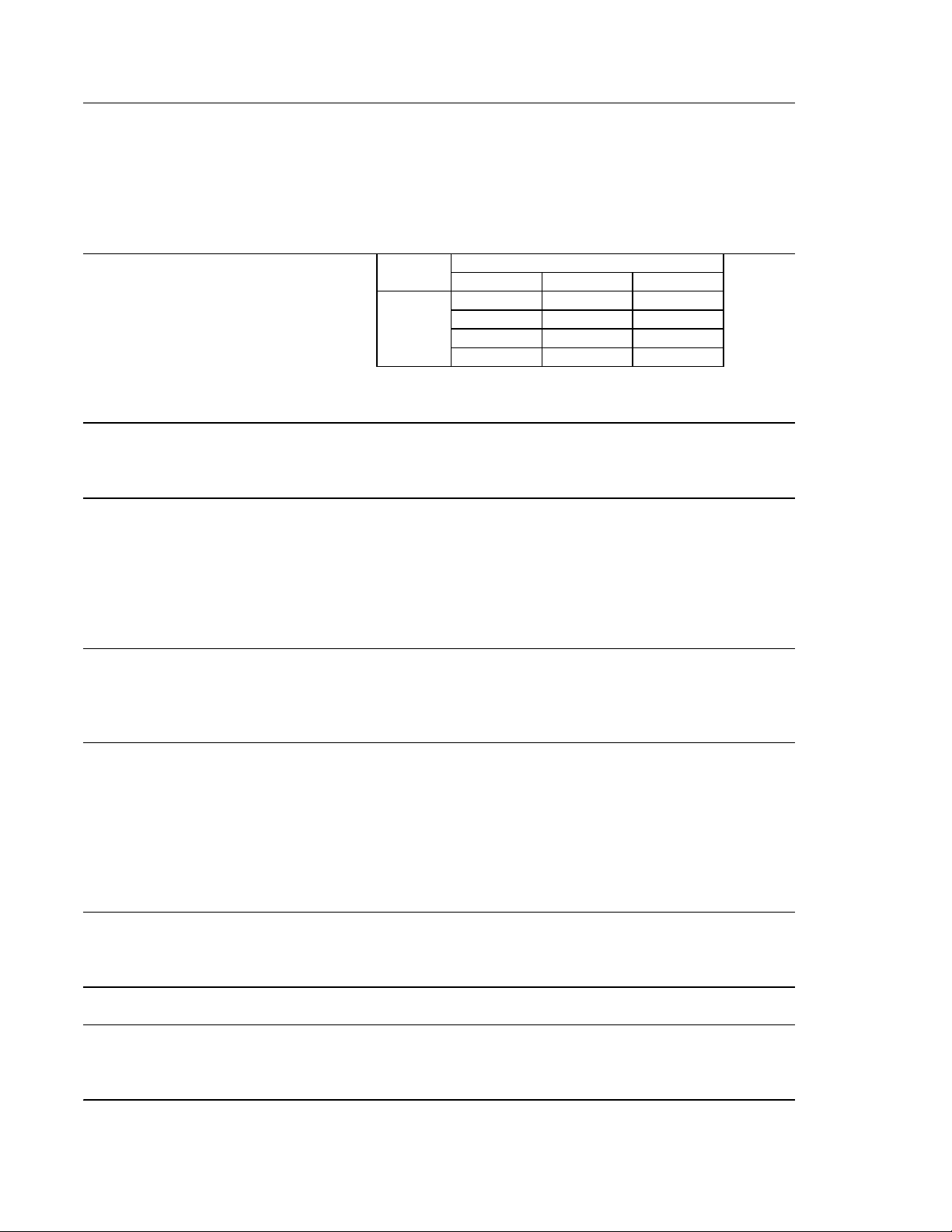
F-2000MRH-C
AC SUPPLY VOLTAGE 208-230/60/1 (3 wire with neutral for 115V)
COMPRESSOR 240 V 10.8 RLA 96 LRA
GEAR MOTOR 120 V 5.6 FLA 0.54 HP
FAN MOTOR REMOTE 120 V 3A MAX
OTHER 120 V 0.03A
MAXIMUM FUSE SIZE 30 A
MAX. HACR BREAKER (USA ONLY) 30 A
MAX. CIRC. BREAKER (CANADA ONLY) 30 A
MINIMUM CIRCUIT AMP ACITY 30 A
APPROXIMATE ICE PRODUCTION Ambient WATER TEMP. (°F)
PER 24 HR. Temp.(°F) 50 70 90
lbs./day ( kg/day ) 70 *1715 (778) 1660 (753) 1630 (739)
Reference without *marks 80 1595 (723) 1560 (708) 1530 (694)
90 1500 (680) *1490 (676) 1435 (651)
100 1410 (640) 1380 (626) *1270 (576)
SHAPE OF ICE Cubelet
ICE QUALITY Approx. 80% , Ice (90/70°F, Conduc tivity 200 µs/ cm)
APPROXIMATE STORAGE CAPACITY N/A
ELECTRIC & WATER CONSUMPTION 90/70°F 70/50°F
ELECTRIC W (kWH/100 lbs.) 2870 (4.6) 2860 (4.0)
POTABLE WATER 179 (12) 205 (12)
gal./24HR (gal./100 lbs.)
EXTERIOR DIMENSIONS (WxDxH) 30" x 27-1/2" x 34-7/16" (762 x 699 x 874mm)
EXTERIOR FINISH Stainless Steel, Galvanized Steel (Rear)
WEIGHT Net 310 lbs. ( 140 kg ), Shipping 342 lbs. ( 155 kg )
CONNECTIONS - E LECTRIC Permanent - Connec tion
- WATER SUPPLY Inlet 1/2" FPT
- DRAIN Outlet 3/4" FPT
- REFRIGERATION Discharge line 1-1/16-12 UNF Fitting (#10 AEROQUIP)
CIRCUIT Liquid line 5/8-18 UNF Fitting (#6 AEROQUIP)
ICE MAKING SYSTEM Auger type
HARVESTING SYSTEM Direct Driven Auger ( 400 W Gear Mot or )
ICE MAKING WATER CONTROL Float Switc h
COOLING W ATER CONTROL N/ A
BIN CONTROL SYSTEM Mechanical Bin Control ( Proximity Sw. )
COMPRESSOR Hermetic, Model CS20-K6E-PFV
CONDENS ER Air-cooled Remote Condenser unit URC-20F Recommended
EVAPORATOR Copper Tube on Cylinder
REFRIGERANT CONTROL Thermostatic Ex pans ion Valve
Condensing Pressure Regulator on URC-20F
REFRIGERANT CHARGE R-404A, 14 lb. 9 oz. (6600g)
(Ice Maker: 6 lb. 14 oz ., Cond. Unit: 7 lb. 11 oz . )
DESIGN PRESSURE High 460 PSIG, Low 290 PSIG
P.C. BOARD CIRCUIT PROTECTION High Voltage Cut-off Relay
COMPRESSOR PROTECTION Internal Protector
GEAR MOTOR PROTECTION Manual Reset Circuit Breaker & Thermal Protector
REFRIGERANT CIRCUIT PROTECTION Auto-reset High Pressure Control Switch
LOW WATER PROTECTION Float Switch and Timer
BIN CONTROL PROTECTION Manual Reset S pout Cont rol
ACCESSORIES -SUPPLIED Spare Fuse
-REQUIRED Ice Storage Bin
OPE RATING CONDITIONS VOLTAGE RANGE 187-253 V
AMBIENT TEMP. 45-100° F
WATER SUPPLY TEMP. 45-90° F
WATER SUPPLY PRESSURE 10-113 PSIG
We reserve the right to make changes in specifications and design without prior notice.
8
Page 9
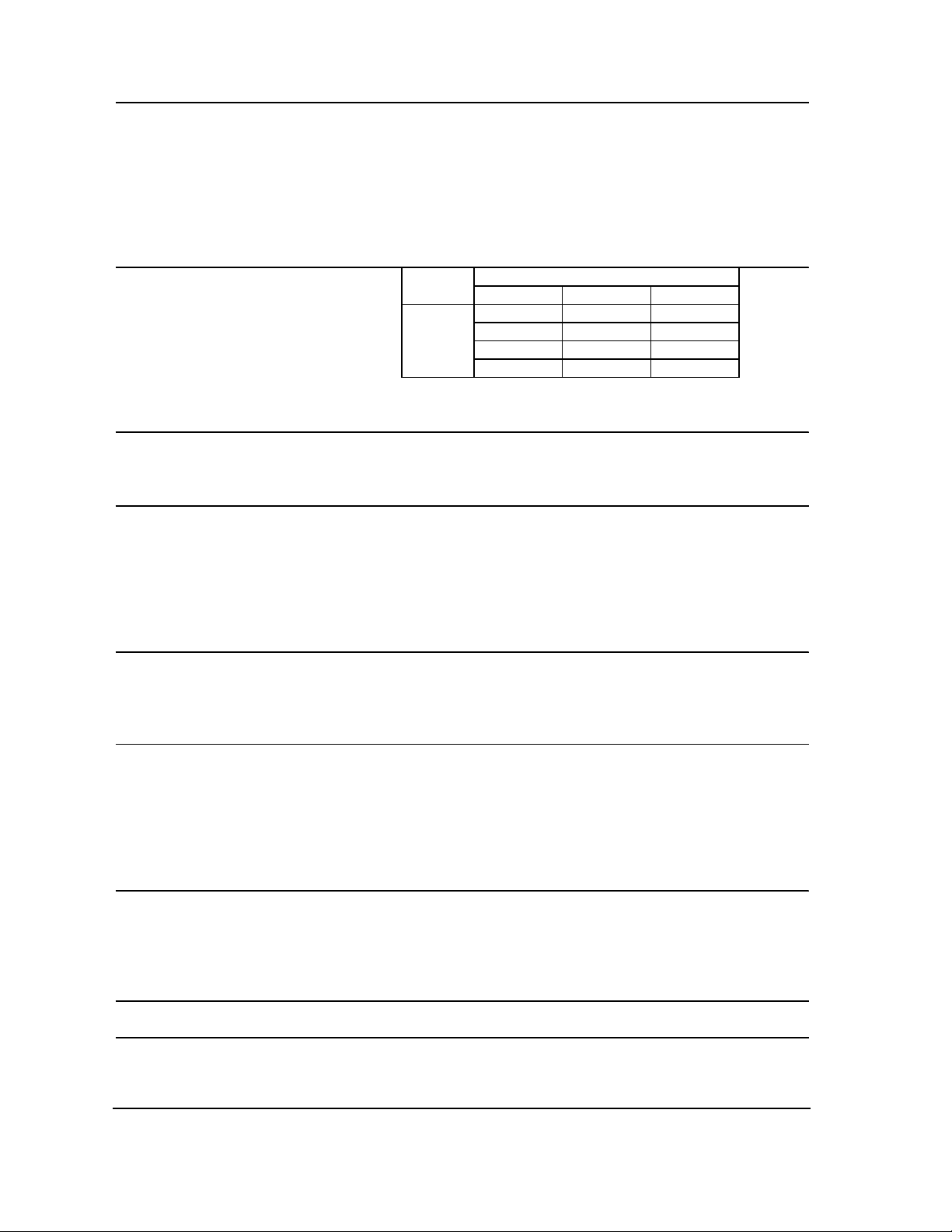
F-2000MRH3
AC SUPPLY VOLTAGE 208-230/60/3
COMPRESSOR 240 V 9.0 RLA 75 LRA
GEAR MOTOR 120 V 5.6 FLA 0.54 HP
FAN MOTOR REMOTE 120 V 3A MAX
OTHER 120 V 0.03A
MAXIMUM FUSE SIZE 20 A
MAX. HACR BREAKER (USA ONLY) 20 A
MA X. CIRC. BREAKER (CANADA ONLY) 20 A
MINIMUM CIRCUIT AMP ACITY 20 A
APPROXIMATE ICE PRODUCTION Ambient WATER TEMP. (°F)
PER 24 HR. Temp.(°F) 50 70 90
lbs./day ( k g/day ) 70 *2010 (912) 1950 (885) 1895 (860)
Reference without *marks 80 1845 (837) 1795 (814) 1750 (794)
90 1700 (771) *1695 (769) 1610 (730)
100 1570 (712) 1525 (692) *1410 (640)
SHAPE OF ICE Flake
ICE QUALITY Approx. 70%, Ice (90/70°F, Conduct ivity 200 µs/cm)
APPROXIMATE STORAGE CAPACITY N/A
ELECTRIC & WATER CONSUMPTION 90/70°F 70/50°F
ELECTRIC W (kW H/100 lbs.) 2865 (4.1) 2850 (3.4)
POTABLE W ATER 203 (12) 240 (12)
gal./24HR (gal./100 lbs.)
EXTERIOR DIMENSIONS (W x DxH) 30" x 27-1/2" x 34-7/16" (762 x 699 x 874mm)
EXTERIOR FINISH Stainless Steel, Galvanized Steel (Rear)
WEIGHT Net 326 lbs. ( 148 kg ), Shipping 359 lbs. ( 163 k g )
CONNECTIONS - ELECTRIC Permanent - Connection
- WATER SUPPLY Inlet 1/2" FPT
- DRAIN Outlet 3/4" FPT
- REFRIGERATION Discharge line 1-1/16-12 UNF Fitting (#10 AEROQUIP)
CIRCUIT Liquid line 5/8-18 UNF Fitting (#6 AEROQUIP)
ICE MAKING SYSTEM Auger ty pe
HARVESTING SYSTEM Direc t Driven Auger ( 400 W Gear Motor )
ICE MAKING WATER CONTROL Float Switc h
COOLING WATER CONTROL N/A
BIN CONTROL SYS TEM Mechanical Bin Control ( Proximity S w. )
COMPRESSOR Hermet ic , Model CS20-K6E -TF5
CONDENSER Air-cooled Remote Condenser unit URC-20F Recommended
EVAPORATOR Copper Tube on Cylinder
REFRIGERANT CONTROL Thermost atic Expansion Valve
Condensing Pressure Regulator on URC-20F
REFRIGERANT CHARGE R-404A, 14 lb. 9 oz. (6600g)
(Ice Maker: 6 lb. 14 oz ., Cond. Unit: 7 lb. 11 oz. )
DESIGN PRESSURE High 460 PSIG, Low 290 PSIG
P.C. BOARD CIRCUIT PROTECTION Fuse
COMPRESSOR PROTECTION Internal Protector
GEAR MOTOR PROTECTION Manual Reset Circuit Breaker & Thermal Protec tor
REFRIGERANT CIRCUIT PROTECTION Auto-res et High Press ure Control Switch
LOW WATER PROTECTION Float Switch and Timer
BIN CONTROL PROTECTION Manual Res et Spout Control
ACCESSORIES -SUPPLIED Spare Fuse
-REQUIRED Ice Storage Bin
OPERATING CONDITIONS VOLTAGE RANGE 187-253 V
AMB IENT TEMP. 45-100° F
WA TER SUPPLY TEMP. 45-90° F
WATER SUPPLY PRESSURE 10-113 PSIG
We reserve the right to make changes in specifications and design without prior notice.
9
Page 10
F-2000MRH3-C
)
AC SUPPLY VOLTAGE 208-230/60/3
COMPRESSOR 240 V 9.0 RLA 75 LRA
GEAR MOTOR 120 V 5.6 FLA 0.54 HP
FAN MOTOR REMOTE 120 V 3A MAX
OTHER 120 V 0.03A
MAXIMUM FUSE SIZE 20 A
MAX. HACR BREAKER (USA ONLY) 20 A
MAX. CIRC. BREAKER (CANADA ONLY) 20 A
MINIMUM CIRCUIT AMPACITY 20 A
APPROXIMATE ICE PRODUCTION Ambient WATER TEMP. (°F)
PER 24 HR. Temp.(°F
lbs./day ( k g/day ) 70 *1725 (782) 1685 (764) 1650 (748)
Reference without *marks 80 1615 (733) 1580 (717) 1545 (701)
90 1515 (687) *1525 (692) 1450 (658)
100 1420 (644) 1390 (631) *1275 (578)
SHAPE OF ICE Cubelet
ICE QUALITY Approx. 80%, Ice (90/70°F, Conduct ivity 200 µs/cm)
APPROXIMATE STORAGE CAPACITY N/A
ELECTRIC & WATER CONSUMPTION 90/70°F 70/50°F
ELECTRIC W (kW H/100 lbs.) 3000 (4.6) 2970 (4.1)
POTABLE W ATER 183 (12) 207 (12)
gal./24HR (gal./100 lbs.)
EXTERIOR DIMENSIONS (W xDxH) 30" x 27-1/2" x 34-7/16" (762 x 699 x 874mm)
EXTERIOR FINIS H Stainles s St eel, Galvaniz ed Steel (Rear)
WEIGHT Net 310 lbs . ( 140 kg ), Shipping 342 lbs . ( 155 kg )
CONNECTIONS - ELECTRIC Permanent - Connection
- WATER SUPPLY Inlet 1/2" FPT
- DRAIN Outlet 3/4" FPT
- REFRIGERATION Discharge line 1-1/16-12 UNF Fitting (#10 AEROQUIP)
CIRCUIT Liquid line 5/8-18 UNF Fitting (#6 AEROQUIP)
ICE MAKING SYSTEM Auger type
HARVESTING SYSTEM Direct Driven Auger ( 400 W Gear Motor )
ICE M AKING WATER CONTROL Float S witc h
COOLING WATER CONTROL N/A
BIN CONTROL SYS TEM Mechanical Bin Control ( Proximit y Sw. )
COMPRESSOR Hermetic, Model CS20-K6E-TF5
CONDENSER Air-cooled Remote Condens er unit URC-20F Recommended
EVAPORATOR Copper Tube on Cylinder
REFRIGERANT CONTROL Thermostat ic Expans ion V alve
Condensing Pressure Regulator on URC-20F
REFRIGERANT CHARGE R-404A, 14 lb. 9 oz. (6600g)
(Ice Maker: 6 lb. 14 oz., Cond. Unit: 7 lb. 11 oz. )
DESIGN PRESSURE High 460 PSIG, Low 290 PSIG
P.C. BOARD CIRCUIT PROTECTION High Voltage Cut -off Relay
COMPRESSOR PROTECTION Internal Protector
GEAR MOTOR PROTECTION Manual Reset Circuit Break er & Thermal Protect or
REFRIGERANT CIRCUIT PROTECTION Auto-reset High Pressure Control Switch
LOW WATER PROTECTION Float Switch and Timer
BIN CONTROL PROTECTION Manual Reset Spout Control
ACCESSORIES -SUPPLIED Spare Fuse
-REQUIRED Ice Storage Bin
OPERATING CONDITIONS VOLTAGE RANGE 187-253 V
AMBIENT TEMP. 45-100° F
WATER SUPPLY TEMP. 45-90° F
WATER SUPPLY PRESSURE 10-113 PSIG
We reserve the right to make changes in specifications and design without prior notice.
50 70 90
10
Page 11
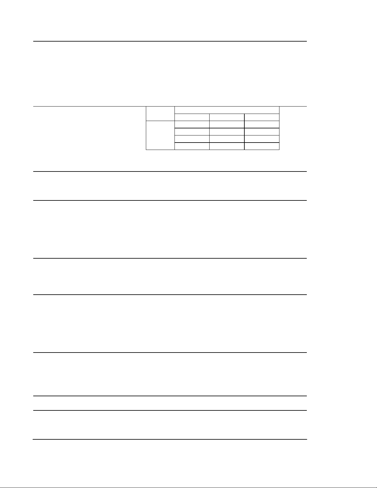
F-2000MLH
AC SUPPLY VOLTAGE 115/60/1
GEAR MOTOR 120 V 5.6 FLA 0.54 HP
FAN MOTOR 120 V 0. 51 FLA 8W
OTHER 120 V 0.03A
MAXIMUM FUSE SIZE 15 A
MAX. HACR BREAKER (USA ONLY) 15 A
MAX. CIRC. BREAKER (CANADA ONLY) 15 A
MINIMUM CIRCUIT AMPACITY 15 A
APPROXIMATE ICE PRODUCTION Ambient WATER TEMP. (°F)
PER 24 HR. Temp.(°F) 50 70 90
lbs./day ( kg/day ) 70 *2280 (921) 1955 (887) 1915 (869)
Reference without *marks 80 2010 (851) 1835 (832) 1795 (814)
90 1900 (862) *1730 (785) 1685 (764)
100 1650 (748) 1615 (733) *1370 (680)
SHAPE OF ICE Flake
ICE QUALITY Approx . 70%, Ice (90/70°F, Conductivity 200 µs/cm)
APPROXIMATE STORAGE CAPACITY N/A
ELECTRIC & WATER CONSUMPTION 90/70°F 70/50°F
ELECTRIC W (kWH/100 lbs.) 470 (0.6) 490 (0.5)
POTABLE W ATER 207 (12) 258 (12)
gal./24HR (gal./100 lbs.)
EXTERIOR DIMENSIONS (WxDxH) 30" x 27-1/2" x 34-7/16" (762 x 699 x 874mm)
EXTERIOR FINISH Stainless Steel, Galvanized Steel (Rear)
WEIGHT Net 216 lbs . ( 98 kg ), Shipping 250 lbs. ( 113 kg )
CONNECTIONS - ELECTRIC Permanent - Connection
- WATER SUPPLY Inlet 1/2" FPT
- DRAIN Outlet 3/4" FPT
- REFRIGERATION Suction line 1-1/16-12 UNF Fitting (#10 AEROQUIP)
CIRCUIT Liquid line 5/8-18 UNF Fitting (#6 AEROQUIP)
ICE MAKING SYSTEM Auger type
HARVESTING SYSTEM Direct Driven Auger ( 400 W Gear Motor )
ICE MAKING W ATER CONTROL Float Switch
COOLING WATER CONTROL N/A
BIN CONTROL SYSTEM Mechanical Bin Control ( Proximity Sw. )
CONDENSING UNIT Required capacity for ice maker is 11600 BTU/h at discharge
press ure 221 P SIG and suction press ure 22 PSIG with R404A
refrigerant.
Suction pres sire needs t o be less than 22 PSIG.
EVAPORATOR Copper Tube on Cylinder
REFRIGERANT CONTROL Thermostatic Expansion Valve
Evaporator Pressure Regulator
REFRIGERANT CHARGE R-404A, 3.5 oz. (100g)
DESIGN PRESSURE High 460 PSIG, Low 290 PSIG
P. C. BOARD CIRCUIT PROTECTION High Voltage Cut-off Relay
GEAR MOTOR PROTECTION Manual Reset Circuit Breaker & Thermal Protector
LOW WATER PROTECTION Float Switch and Timer
BIN CONTROL PROTECTION Manual Res et Spout Control
ACCESSORIES -SUPPLIED Spare Fuse
-REQUIRED Ice Storage Bin
OPERATING CONDITIONS VOLTAGE RANGE 104-127 V
AMBIENT TEMP. 45-100° F
W A TE R SUP P LY TE M P . 45-90° F
WATER SUPPLY PRESSURE 10-113 PSIG
We reserve the right to make changes in specifications and design without prior notice.
11
Page 12
F-2000MLH-C
AC SUPPLY VOLTAGE 115/60/1
GEAR MOTOR 120 V 5.6 FLA 0.54 HP
FAN MOTOR 120 V 0.51 FLA 8W
OTHER 120 V 0.03A
MAXIMUM FUSE SIZE 15 A
MAX. HACR BREAKER (USA ONLY) 15 A
MAX. CIRC. BREAKER (CANADA ONLY) 15 A
MINIMUM CIRCUIT AMPACITY 15 A
APPROXIMATE ICE PRODUCTION Ambient WATER TEMP. (°F)
PE R 24 HR. Temp. (°F) 50 70 90
lbs./day ( kg/day ) 70 *1965 (891) 1680 (762) 1660 (753)
Reference without *marks 80 1755 (796) 1615 (732) 1585 (719)
90 1565 (710) *1540 (699) 1515 (687)
100 1500 (680) 1475 (669) *1245(680)
SHAPE OF ICE Cubelet
ICE QUALITY Approx. 80%, Ice (90/70°F, Conduc tivity 200 µs/c m)
APPROXIMATE STORAGE CAPACITY N/A
ELECTRIC & WATER CONSUMPTION 90/70°F 70/50°F
ELECTRIC W (kWH/100 lbs.) 470 (0.7) 490 (0.6)
POTABLE WATER 185 (12) 235 (12)
gal./24HR (gal./100 lbs.)
EXTERIOR DIMENSIONS (WxDxH) 30" x 27-1/2" x 34-7/16" (762 x 699 x 874mm)
EXTERIOR FINISH Stainless Steel, Galvanized Steel (Rear)
WEIGHT Net 216 lbs. ( 98 kg ), Shipping 250 lbs. ( 113 kg )
CONNECTIONS - ELECTRIC Perm anent - Connection
- WATER SUPPLY Inlet 1/2" FPT
- DRAIN Outlet 3/4" FPT
- REFRIGERATION Suction line 1-1/16-12 UNF Fitting (#10 AEROQUIP)
CIRCUIT Liquid line 5/8-18 UNF Fitting (#6 AEROQUIP)
ICE MAKING SYSTEM Auger type
HARVESTING SYSTEM Direct Driven Auger ( 400 W Gear Motor )
ICE MAKING WATER CONTROL Float Switch
COOLING WATER CONTROL N/A
BIN CONTROL SYSTEM Mechanical Bin Control ( Proximity Sw. )
CONDENSING UNIT Required capacity for ice maker is 11600 BTU/h at discharge
pressure 221 PSIG and suction pressure 22 PSIG with R404A
refrigerant.
Suction pres sire needs to be less than 22 PSIG.
EVAPORATOR Copper Tube on Cylinder
REFRIGERANT CONTROL Thermostatic Expansion Valve
Evaporator Pressure Regulat or
REFRIGERANT CHARGE R-404A, 3.5 oz. (100g)
DESIGN PRESSURE High 460 PSIG, Low 290 PSIG
P. C. BOARD CIRCUIT PROTECTION High Voltage Cut-off Relay
GEAR MOTOR PROTECTION Manual Reset Circuit Breaker & Thermal Protector
LOW WATER PROTECTION Float Switch and Timer
BIN CONTROL PROTECTION Manual Reset Spout Control
ACCESSORIES -SUPPLIED Spare Fuse
-REQUIRED Ice Storage Bin
OPERATING CONDITIONS VOLTAGE RANGE 104-127 V
AMBIENT TEMP. 45-100° F
WATER SUPPLY TEMP. 45-90° F
WATER SUPPLY PRESSURE 10-113 PSIG
We reserve the right to make changes in specifications and design without prior notice.
12
Page 13
2. CONDENSER UNIT
URC-20F
13
Page 14

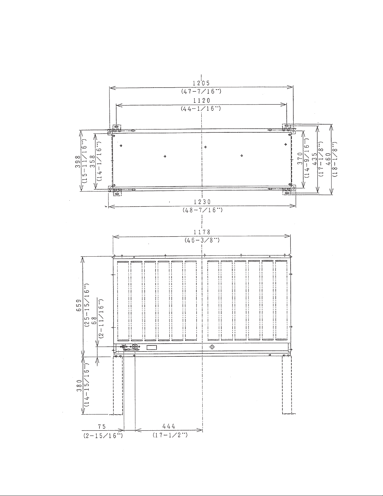
SPECIFICATIONS
MODEL: URC-20F
EXTERIOR Galvanized Steel
DIMENSIONS (W x D x H) 46-3/8" x 15-11/16" x 25-15/16"
(1178 x 398 x 659 mm)
REFRIGERANT CHARGE
URC-20F R404A 7 lbs. 11 oz. (3500 g)
WEIGHT Net 104 lbs. (47 kg)
Shipping 115 lbs. (52 kg)
CONNECTIONS
REFRIGERANT One Shot Couplings (Aeroquip)
ELECTRICAL Permanent Connection
CONDENSER Air-cooled
HEAD PRESSURE CONTROL Condensing Pressure Regulator
AMBIENT CONDITION Min. -20°F - Max. +122°F
(-29°C to +50°C)
Outdoor use
14
Page 15
II. GENERAL INFORMATION
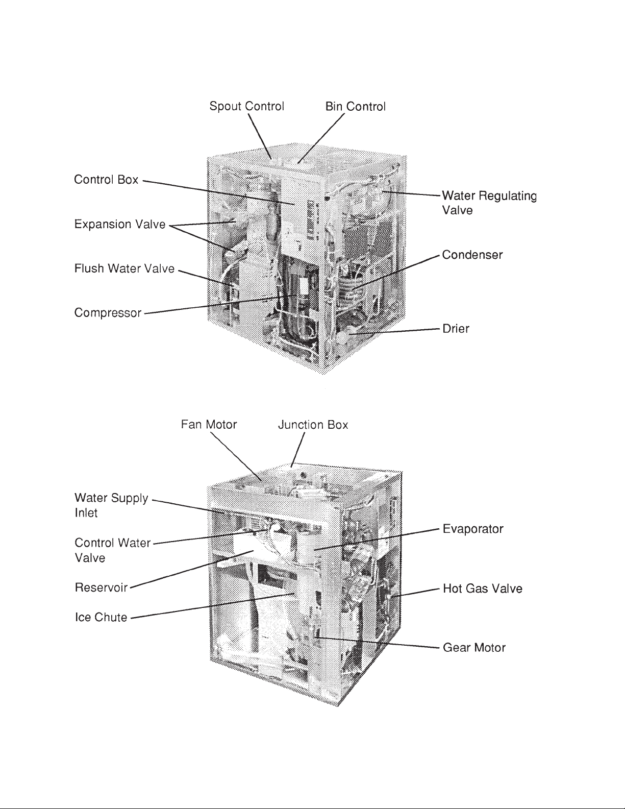
1. CONSTRUCTION
F-2000MWH/-C
15
Page 16
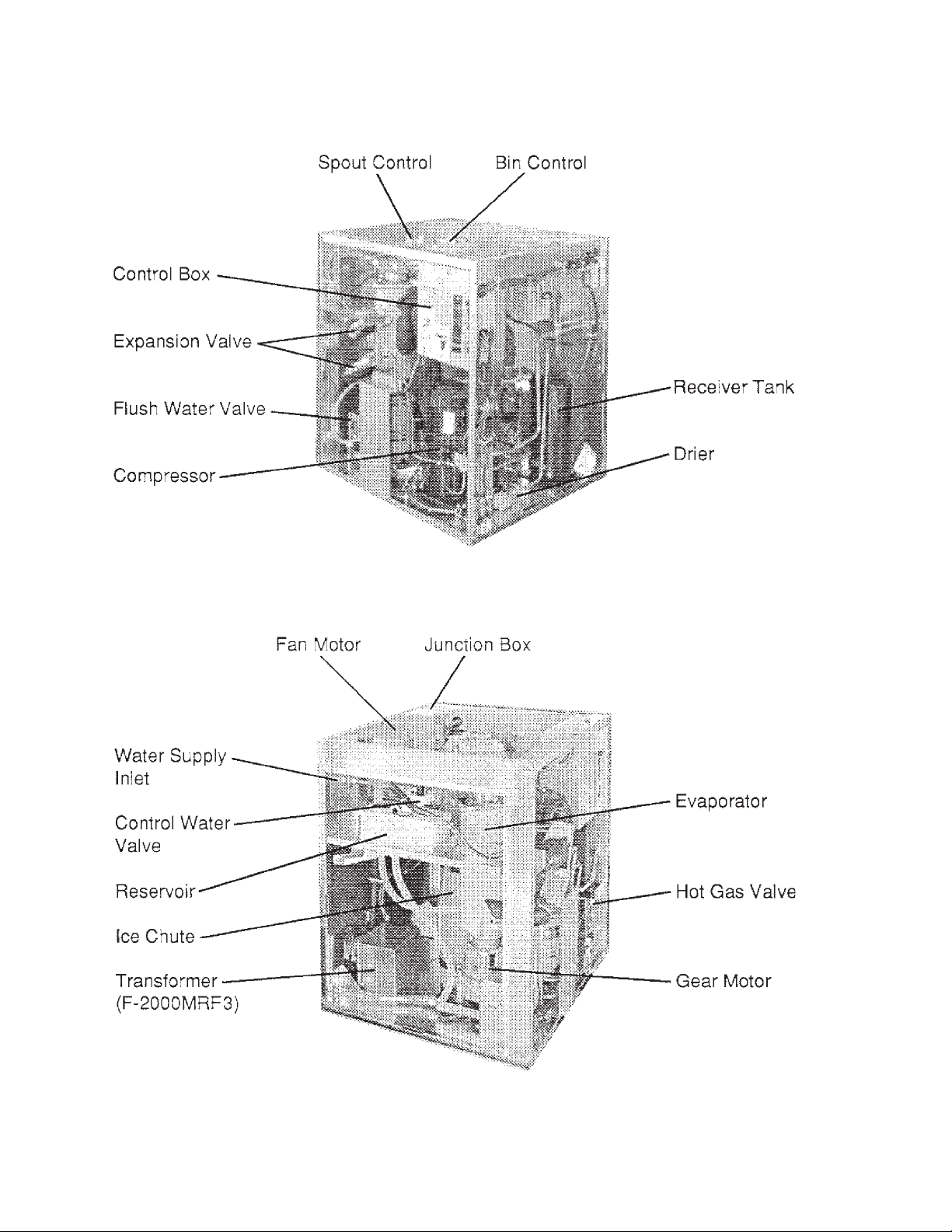
F-2000MRH/-C, F-2000MRH3/-C
16
Page 17
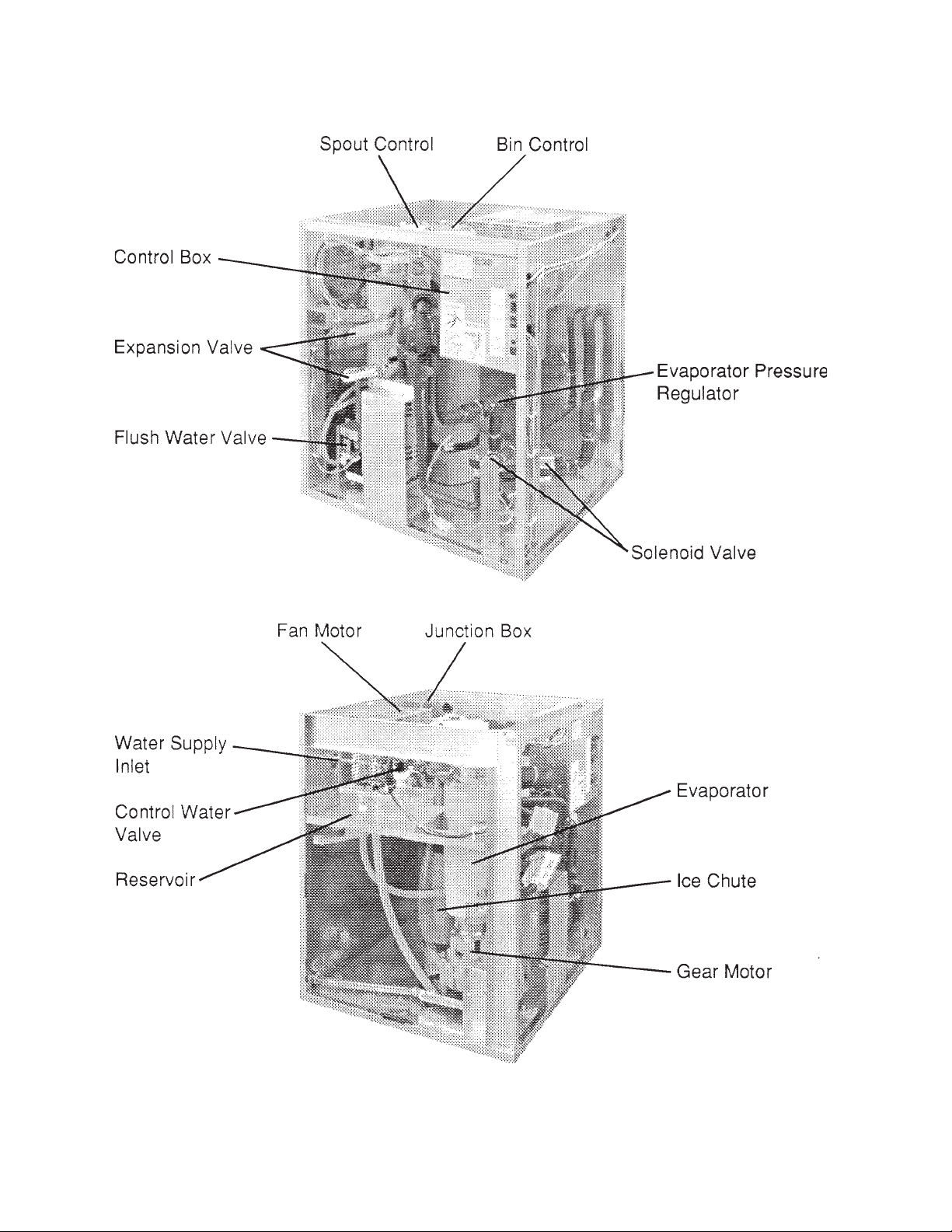
F-2000MLH/-C
17
Page 18
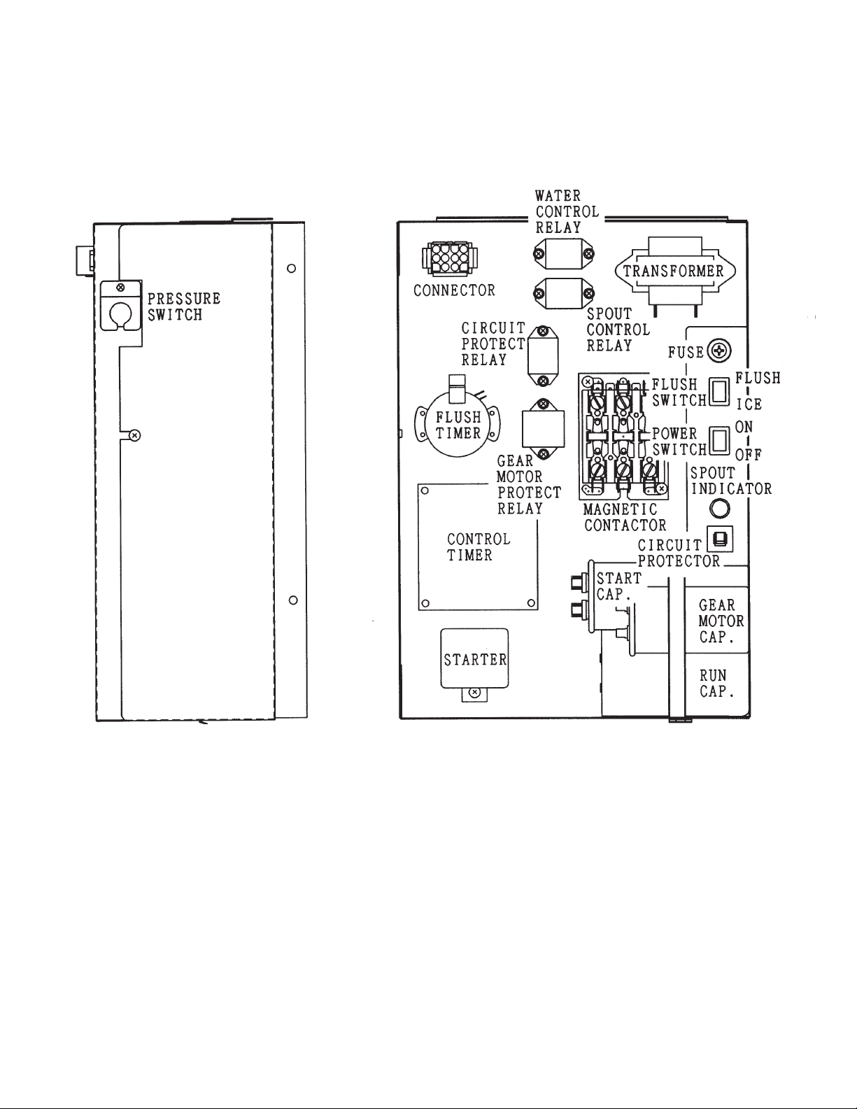
2. CONTROL BOX LAYOUT
F-2000MWH/-C, F-2000MRH/-C
Note: The above component names are identical with the Wiring Label, but not with
the Parts List.
18
Page 19
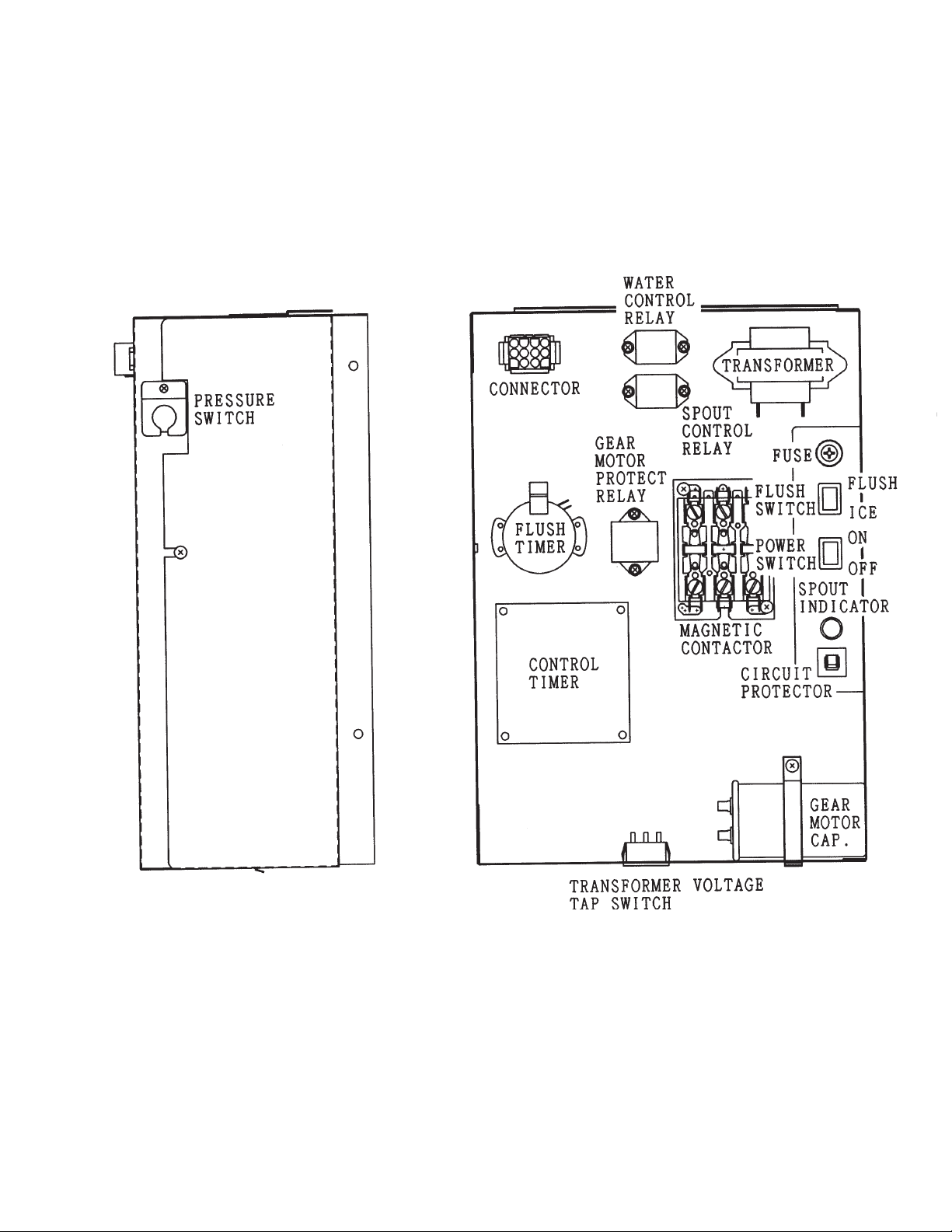
F-2000MRH3/-C
19
Page 20
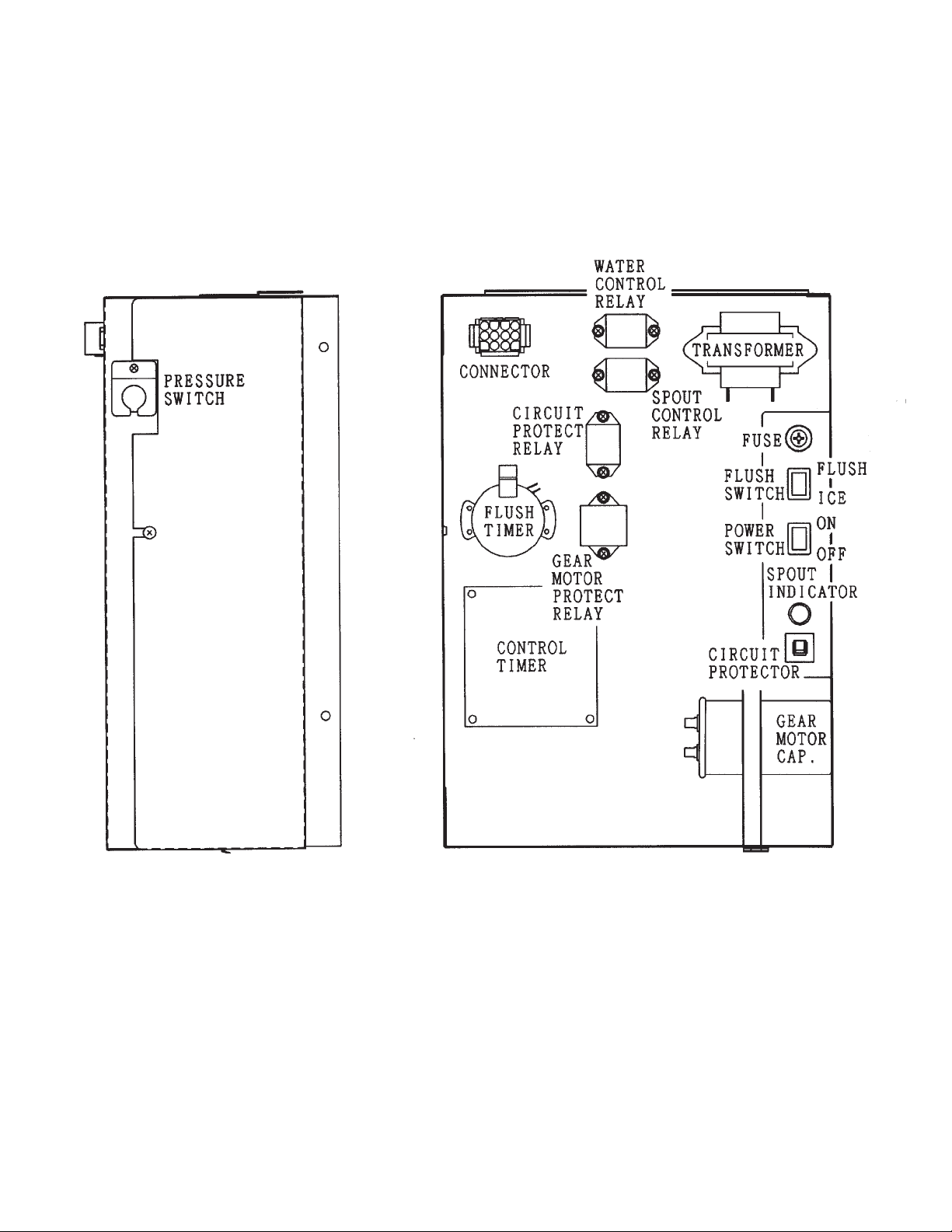
F-2000MLH/-C
20
Page 21
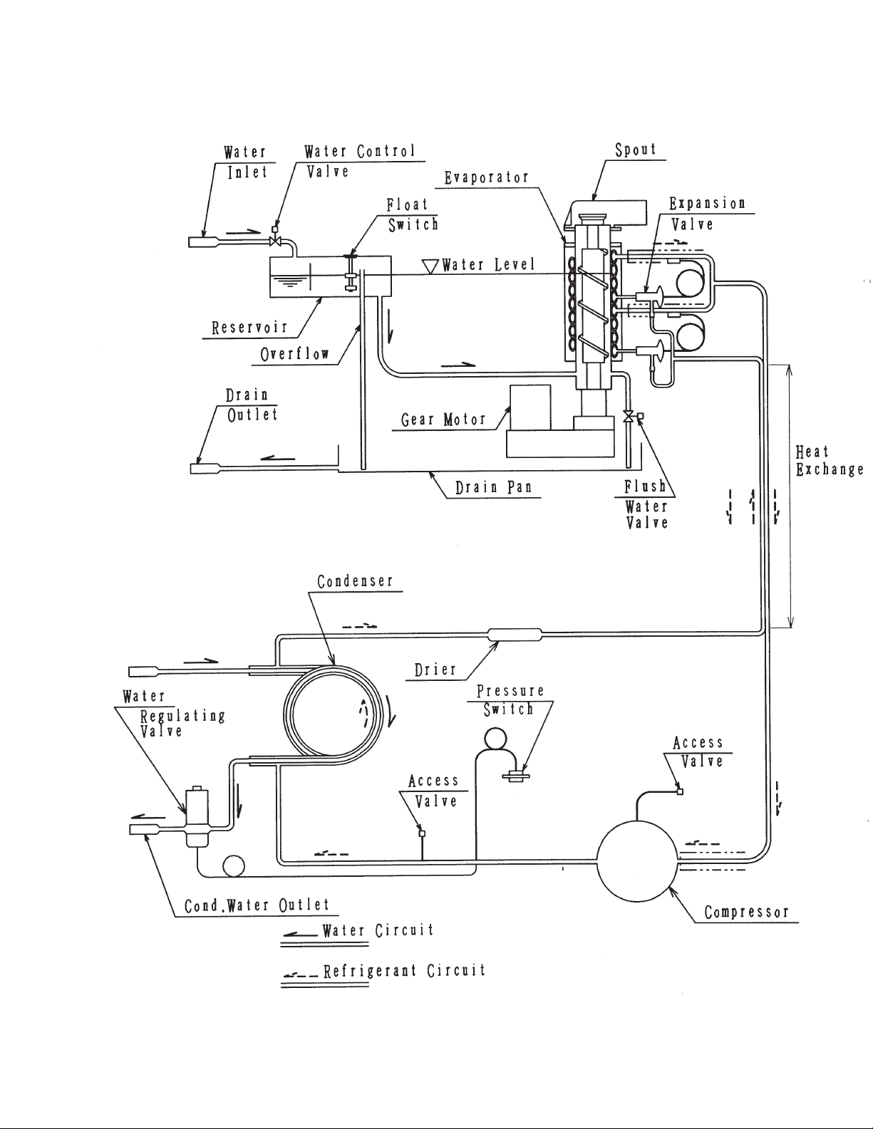
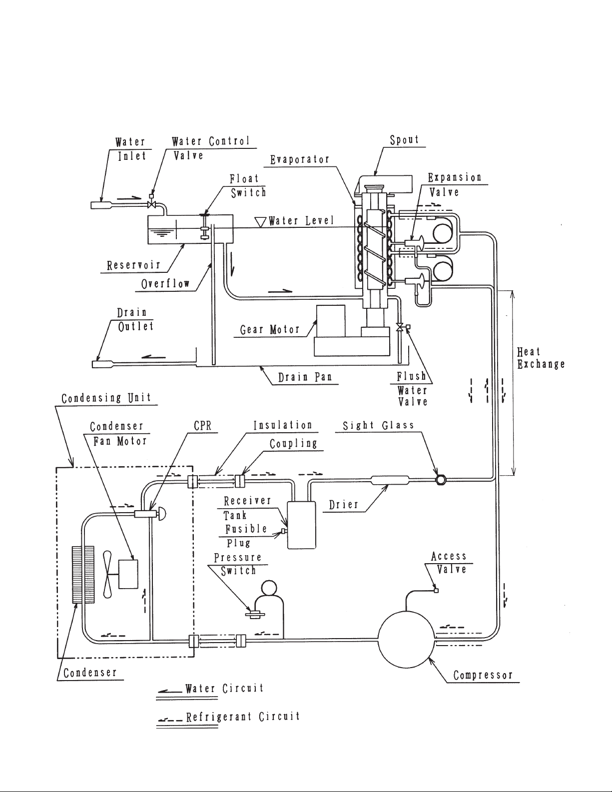
III. TECHNICAL INFORMATION
1. WATER CIRCUIT AND REFRIGERATION CIRCUIT
F-2000MWH/-C
21
Page 22
F-2000MRH/-C, F-2000MRH3/-C
22
Page 23
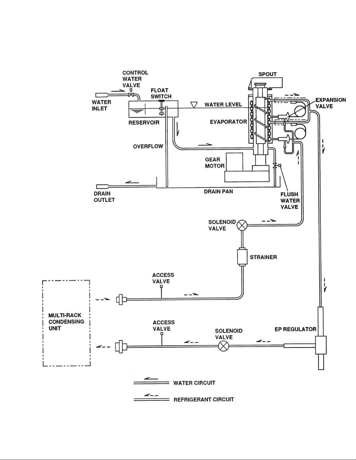
F-2000MLH/-C
23
Page 24
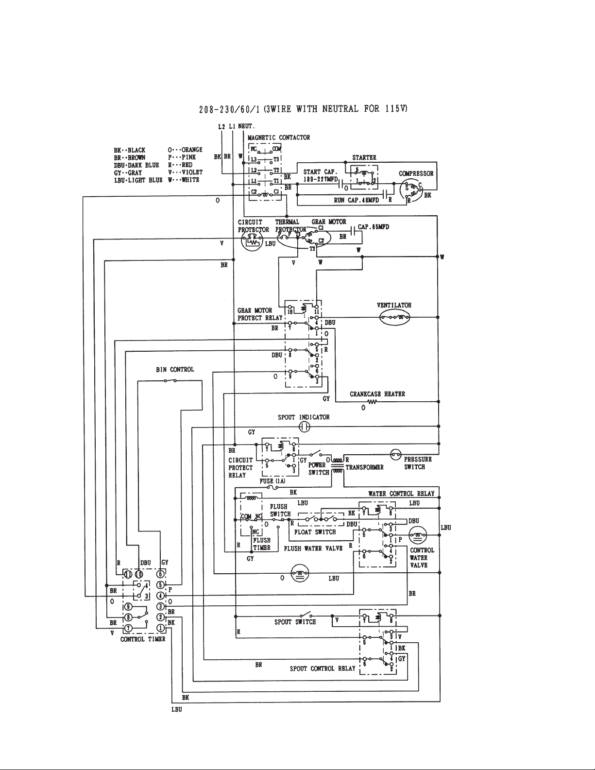
2. WIRING DIAGRAMS
F-2000MWH/-C
24
Page 25
F-2000MRH/-C
25
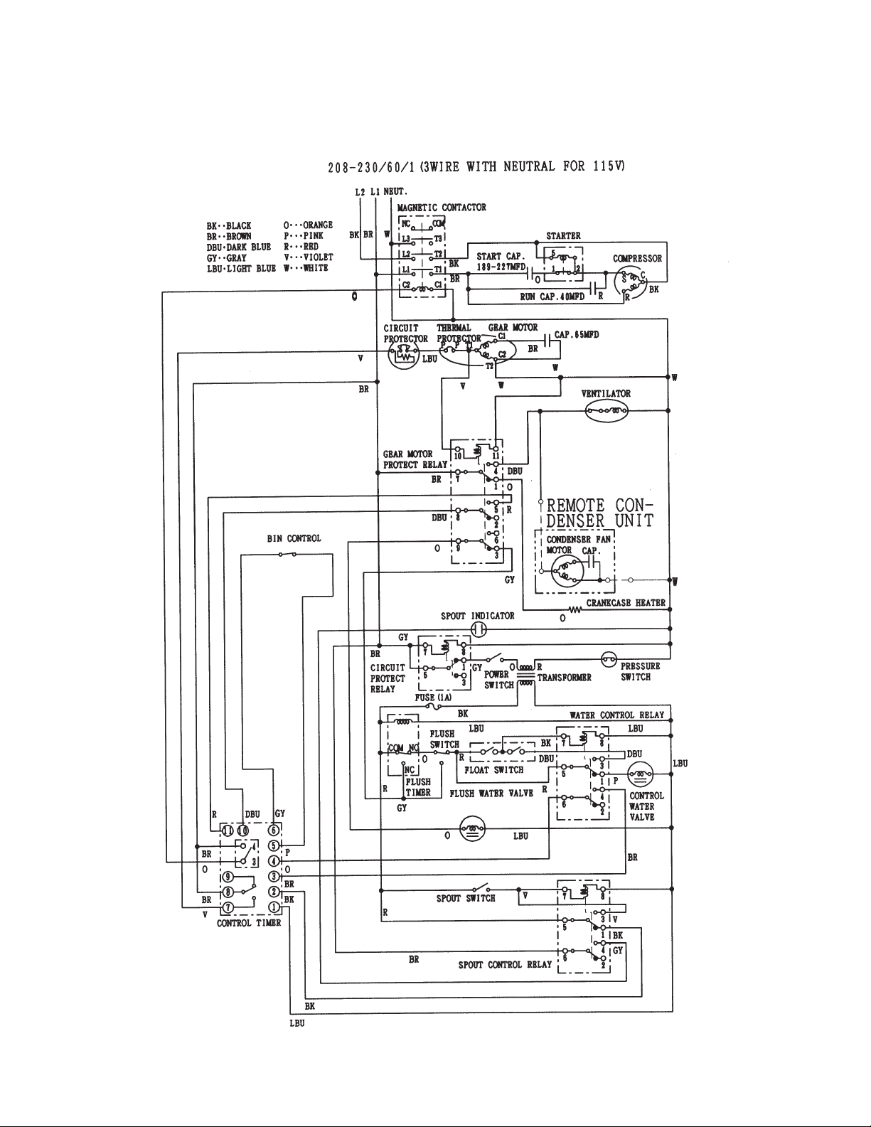
Page 26

F-2000MRH3/-C
26
Page 27

F-2000MLH/-C
27
Page 28

3. SEQUENCE OF ELECTRICAL CIRCUIT
[a] When Power Switch is moved to “ON” position and Flush Switch to “ICE” position,
water starts to be supplied to Reservoir.
28
Page 29

[b] When Reservoir has been filled, Gear Motor starts immediately.
29
Page 30

[c] Compressor starts [F-2000MLH/-C only, two solenoid valves open] about 60 sec.
after Gear Motor starts.
30
Page 31

[d] Bin Control operates, and about 6 sec. later, Compressor and Gear Motor stop
simultaneously. (F-2000MLH/-C, two solenoid valves close.)
31
Page 32

[e] Low Water (Except Water-cooled Model where Compressor will operate
intermittently)
32
Page 33

[f] When Flush Timer operates (for 15 min. every 12 hours) or when Flush Switch is
moved to “FLUSH” position, Flush Water Valve opens and flushes Reservoir and
Evaporator.
33
Page 34

[g] For single-phase machines, when 208-230V are supplied to Circuit Protect
Relay, it protects the circuit from being miswired. If the power supply is properly
connected, the contact of Circuit Protect Relay does not move even when the
coil is energized.
34
Page 35

[h] When Pressure Switch opens, power supply to the control board is cut off causing the
Compressor and Gear Motor to turn off immediately.
35
Page 36

4. TIMING CHART
1. CIRCUIT PROTECT
RELAY
2. WATER LEVEL
ON
OFF
UPPER
LOWER
BOTTOM
Proper wiring. The unit starts.
BIN CONTROL
OFF ON
UPPER
3. FLOAT
SWITCH
LOWER
4. WATER CONTROL
RELAY
5. CONTROL WATER
VALV E
6. FLUSH TIMER
7. FLUSH SWITCH
8. FLUSH WATER
VALV E
9. BIN CONTROL
0. GEAR MOTOR
RELAY
ON
OFF
ON
OFF
ON
OFF
ON
OFF
1 - 2
2 - 3
FLUSH
ICE
ON
OFF
ON
OFF
ON
OFF
1 sec
6 sec 1 sec
1. GEAR MOTOR
2. FAN MOTOR
3. COMPRESSOR OR
TWO SOLENOID
VALVES (2000MLF(-C))
4. PRESSURE
SWITCH
5. HEATER
ON
OFF
ON
OFF
ON
OFF
ON
OFF
ON
OFF
60 sec
60 sec
36
Page 37

LOW WATER
FLUSH TIMER
1. CIRCUIT PROTECT
RELAY
2. WATER LEVEL
UPPER
3. FLOAT
SWITCH
LOWER
4. WATER CONTROL
RELAY
5. CONTROL WATER
VALV E
6. FLUSH TIMER
7. FLUSH SWITCH
ON
OFF
UPPER
LOWER
BOTTOM
ON
OFF
ON
OFF
ON
OFF
ON
OFF
1 - 2
2 - 3
FLUSH
ICE
15 min every 12 hr
8. FLUSH WATER
VALV E
9. BIN CONTROL
10. GEAR MOTOR
RELAY
11. GEAR MOTOR
12. FAN MOTOR
13. COMPRESSOR OR
TWO SOLENOID
VALVES (2000MLF(-C))
14. PRESSURE
SWITCH
15. HEATER
ON
OFF
ON
OFF
ON
OFF
ON
OFF
ON
OFF
ON
OFF
ON
OFF
ON
OFF
150 sec
90 sec 60 sec 90 sec 60 sec
1 sec
150 sec
1 sec
37
Page 38

38
Page 39

Bin Control broken, and Spout Control operates.
Power Switch OFF and ON. The unit restarts.
1. CIRCUIT PROTECT
RELAY
2. WATER LEVEL
UPPER
3. FLOAT
SWITCH
LOWER
4. WATER CONTROL
RELAY
5. CONTROL WATER
VALV E
6. FLUSH TIMER
7. FLUSH SWITCH
ON
OFF
UPPER
LOWER
BOTTOM
ON
OFF
ON
OFF
ON
OFF
ON
OFF
1 - 2
2 - 3
FLUSH
ICE
8. FLUSH WATER
VALV E
9. BIN CONTROL
10. GEAR MOTOR
RELAY
11. GEAR MOTOR
12. FAN MOTOR
13. COMPRESSOR/
TWO SOLENOID
VALVES (2000MLF(-C))
14. PRESSURE
SWITCH
15. HEATER
ON
OFF
ON
OFF
1 sec
ON
OFF
ON
OFF
ON
OFF
60 sec
ON
OFF
ON
OFF
ON
OFF
39
Page 40

16. SPOUT CONTROL
RELAY
ON
OFF
17. THERMOSTAT/
CONTROL
(2000MWE)
ON
OFF
Compressor Discharge Temp.: 203°FCompressor Discharge Temp.: 225°F
40
Page 41

5. PERFORMANCE DATA
F-2000MWH
APPROXIMATE Ambient Water Temp. (F)
ICE PRODUCTION Temp. (F)
PER 24 HR. 70 2030 (921) 1955 (887) 1915 (869)
80 1875 (851) 1835 (832) 1795 (814)
90 1760 (798) 1730 (785) 1685 (764)
lbs./DAY ( kg/day) 100 1650 (748) 1615 (733) 1500 (680)
APPROXIMATE ELECTRIC 70 2490 -- 2510 -- 2545 -CONSUMPTION 80 2490 -- 2510 -- 2545 --
90 2490 -- 2510 -- 2545 -watts 100 2490 -- 2510 -- 2545 -APP ROXIMA TE W ATE R 70 9 81 (3.71) 1266 (4.79) 2057 (7.79)
CONSUMPTION PER 24 HR. 80 1023 (3.87) 1319 (4.99) 2163 (8.19)
(TOTAL) 90 1062 (4.02) 1374 (5.20) 2278 (8.62)
gal. / day (m
EVAPORATOR OUTLET TEMP. 70 11 (-12) 11 (-12) 11 (-12)
°F (°C) 80 11 (-12) 11 (-12) 11 (-12)
HEAD PRESSURE 70 262 (18.4) 263 (18.5) 265 (18.6)
PSIG (kg/s q.cmG) 100 262 (18.4) 263 (18.5) 265 (18.6)
SUCTION PRESSURE 70 26 (1.8) 27 (1.9) 28 (2.0)
PSIG (kg/sq.cmG) 80 26 (1.8) 27 (1.9) 28 (2.0)
WATER FLOW FOR CONDENSER 97 gal/h (AT 100°F /WT 90°F)
HEA T OF REJECTION FROM CONDENSER 15530 BTU/h (AT 90°F / W T 70°F)
HEA T OF REJECTION FROM COMPRESSOR 2910 BTU/h (AT 90°F /WT 70°F)
3
/day) 100 1105 (4.18) 1442 (5.46) 2513 (9.51)
90 11 (-12) 11 (-12) 11 (-12)
100 11 (-12) 11 (-12) 11 (-12)
80 262 (18.4) 263 (18.5) 265 (18.6)
90 262 (18.4) 263 (18.5) 265 (18.6)
90 26 (1.8) 27 (1.9) 28 (2.0)
100 26 (1.8) 27 (1.9) 28 (2.0)
50 70 90
Note: The data without *marks should be used for reference.
We reserve the right to make changes in specifications and design without prior notice.
41
Page 42

F-2000MWH-C
APPROXIMATE Ambient Water Temp. (F)
ICE PRODUCTION Temp. (F)
PER 24 HR. 70 1790 (812) 1725 (782) 1700 (771)
80 1670 (757) 1640 (744) 1615 (733)
90 1585 (719) 1560 (708) 1535 (696)
lbs./DAY ( kg/day) 100 1510 (685) 1485 (674) 1375 (624)
APPROXIMATE ELECTRIC 70 2555 -- 2585 -- 2640 -CONSUMPTION 80 2555 -- 2585 -- 2640 --
90 2555 -- 2585 -- 2640 -watts 100 2555 -- 2585 -- 2640 -APPROXIMATE WATER 70 978 (3.70) 1281 (4.85) 1985 (7.51)
CONSUMPTION PE R 24 HR. 80 1019 (3.86) 1327 (5.02) 2067 (7.82)
(TOTAL) 90 1051 (3. 98) 1376 (5.21) 2155 (8.16)
gal. / day (m
EVAPORATOR OUTLET TEMP. 70 10 (-12) 10 (-12) 12 (-11)
°F (°C) 80 10 (-12) 10 (-12) 12 (-11)
HEAD PRESSURE 70 262 (18.4) 263 (18.5) 266 (18.7)
PSIG (kg/ sq.cmG) 100 262 (18.4) 263 (18.5) 266 (18.7)
SUCTION PRESSURE 70 27 (1.8) 27 (1.9) 28 (2. 0)
PSIG (kg/sq.cmG) 80 27 (1.8) 27 (1.9) 28 (2.0)
WATER FLOW FOR CONDENSER 92 gal /h (AT 100°F /WT 90°F)
HEAT OF REJECTION FROM CONDENSER 15530 BTU/ h (AT 90°F /WT 70°F)
HEAT OF REJECTION FROM COMPRESSOR 2910 BTU/h (AT 90°F /WT 70°F)
3
/day) 100 1087 (4.11) 1429 (5. 41) 2364 (8.95)
90 10 (-12) 10 (-12) 12 (-11)
100 10 (-12) 10 (-12) 12 (-11)
80 262 (18.4) 263 (18.5) 266 (18. 7)
90 262 (18.4) 263 (18.5) 266 (18. 7)
90 27 (1.8) 27 (1.9) 28 (2.0)
100 27 (1.8) 27 (1.9) 28 (2.0)
50 70 90
Note: The data without *mark s should be used for reference.
We reserve the right to make changes in specifications and design without prior notice.
42
Page 43

F-2000MRH
APPROXIMATE Ambient Water Temp. (F)
ICE PRODUCTION Temp. (F)
PER 24 HR. 70 1990 (902) 1930 (875) 1880 (853)
80 1825 (828) 1775 (802) 1730 (785)
90 1685 (764) 1675 (760) 1595 (723)
lbs./DAY ( kg/day) 100 1550 (703) 1510 (685) 1395 (633)
APPROXIMATE ELECTRIC 70 2770 -- 2770 -- 2775 -CONSUMPTION 80 2775 -- 2780 -- 2780 --
90 2785 -- 2785 -- 2805 -watts 100 2825 -- 2840 -- 2860 -APP ROXIMA TE W A TE R 70 239 (902) 232 (875) 225 (853)
CONSUMPTION PER 24 HR. 80 219 (828) 213 (802) 208 (785)
90 202 (764) 201 (760) 191 (723)
gal. / day (l/day) 100 186 (703) 181 (685) 167 (633)
EVAPORATOR OUTLET TEMP. 70 12 (-11) 12 (-11) 12 (-11)
°F (°C) 80 12 (-11) 12 (-11) 12 (-11)
90 12 (-11) 12 (-11) 14 (-10)
100 14 (-10) 14 (-10) 14 (-10)
HEAD PRESSURE 70 221 (15.5) 221 (15.5) 221 (15.5)
80 230 (16.1) 230 (16.1) 230 (16.1)
90 238 (16.8) 238 (16.7) 238 (16.7)
PSIG (kg/sq.cmG) 100 274 (19.3) 274 (19.3) 274 (19.3)
SUCTION PRESSURE 70 25 (1.8) 25 (1.8) 25 (1.8)
PSIG (kg/sq.cmG) 80 26 (1.8) 26 (1. 8) 26 (1.8)
90 26 (1.8) 26 (1.8) 26 (1.8)
100 29 (2.0) 29 (2.0) 29 (2.0)
CONDENSER V OLUME 214 in
HEA T OF RE JECTION FROM CONDE NSER 16475 BTU/h (A T 90°F /WT 70°F)
HEA T OF RE JECTION FROM COMPRESSOR 2870 BTU/h (AT 90°F / W T 70°F)
50 70 90
3
Note: The data without *marks should be used for reference.
We reserve the right to make changes in specifications and design without prior notice.
43
Page 44

F-2000MRH-C
APPROXIMATE Ambient Water Temp. (F)
ICE PRODUCTION Temp. (F)
PER 24 HR. 70 1715 (778) 1660 (753) 1630 (739)
80 1595 (723) 1560 (708) 1530 (694)
90 1500 (680) 1490 (676) 1435 (651)
lbs./DAY ( kg/day) 100 1410 (640) 1380 (626) 1270 (576)
APPROXIMATE ELECTRIC 70 2860 -- 2860 -- 2865 -CONSUMPTION 80 2865 -- 2865 -- 2865 --
90 2870 -- 2870 -- 2880 -watts 100 2890 -- 2900 -- 2910 -APP ROXIMA TE W A TE R 70 206 (778) 200 (753) 195 (739)
CONSUMPTION PER 24 HR. 80 191 (723) 188 (708) 184 (694)
90 180 (680) 179 (676) 173 (651)
gal. / day (l/day) 100 169 (640) 166 (626) 153 (576)
EVAPORATOR OUTLET TEMP. 70 12 (-11) 12 (-11) 12 (-11)
°F (°C) 80 12 (-11) 14 (-10) 14 (-10)
90 14 (-10) 14 (-10) 14 (-10)
100 14 (-10) 14 (-10) 14 (-10)
HEAD PRESSURE 70 220 (15.5) 220 (15.5) 220 (15.5)
80 227 (15.9) 227 (15.9) 227 (15.9)
90 233 (16.4) 233 (16.4) 233 (16.4)
PSIG (kg/sq.cmG) 100 266 (18.7) 266 (18.7) 266 (18.7)
SUCTION PRESSURE 70 26 (1.8) 26 (1.8) 26 (1.8)
PSIG (kg/sq.cmG) 80 26 (1.8) 26 (1. 8) 26 (1.8)
90 27 (1.9) 27 (1.9) 27 (1.9)
100 29 (2.1) 29 (2.1) 29 (2.1)
CONDENSER V OLUME 214 in
HEA T OF RE JECTION FROM CONDE NSER 17690 BTU/h (A T 90°F /WT 70°F)
HEA T OF RE JECTION FROM COMPRESSOR 2955 BTU/h (AT 90°F / W T 70°F)
50 70 90
3
Note: The data without *marks should be used for reference.
We reserve the right to make changes in specifications and design without prior notice.
44
Page 45

F-2000MRH3
APPROXIMATE Ambient Water Temp. (F)
ICE PRODUCTION Temp. (F)
PER 24 HR. 70 2010 (912) 1950 (845) 1895 (860)
80 1845 (837) 1795 (814) 1750 (794)
90 1700 (771) 1695 (769) 1610 (730)
lbs./DAY ( kg/day) 100 1570 (712) 1525 (692) 1410 (640)
APPROXIMATE ELECTRIC 70 2850 -- 2850 -- 2855 -CONSUMPTION 80 2855 -- 2860 -- 2860 --
90 2865 -- 2865 -- 2875 -watts 100 2890 -- 2890 -- 2910 -APP ROXIMA TE W A TE R 70 241 (912) 234 (845) 228 (860)
CONSUMPTION PER 24 HR. 80 222 (837) 216 (814) 210 (794)
90 204 (771) 203 (769) 194 (730)
gal. / day (l/day) 100 188 (712) 183 (692) 169 (640)
EVAPORATOR OUTLET TEMP. 70 14 (-10) 14 (-10) 14 (-10)
°F (°C) 80 14 (-10) 14 (-10) 14 (-10)
90 14 (-10) 14 (-10) 16 (-9)
100 16 (-9) 16 (-9) 16 (-9)
HEAD PRESSURE 70 219 (15.4) 219 (15.4) 219 (15.4)
80 230 (16.2) 230 (16.2) 230 (16.2)
90 241 (16.9) 241 (16.9) 241 (16.9)
PSIG (kg/sq.cmG) 100 271 (19.0) 271 (19.0) 271 (19.0)
SUCTION PRESSURE 70 25 (1.8) 25 (1.8) 25 (1.8)
PSIG (kg/sq.cmG) 80 26 (1.8) 26 (1. 8) 26 (1.8)
90 27 (1.9) 27 (1.9) 27 (1.9)
100 29 (2.0) 29 (2.0) 29 (2.0)
CONDENSER V OLUME 214 in
HEA T OF RE JECTION FROM CONDE NSER 16890 BTU/h (A T 90°F /WT 70°F)
HEA T OF RE JECTION FROM COMPRESSOR 2860 BTU/h (AT 90°F / W T 70°F)
50 70 90
3
Note: The data without *marks should be used for reference.
We reserve the right to make changes in specifications and design without prior notice.
45
Page 46

F-2000MRH3-C
P
R
APPROXIMATE Ambient W ater Temp. (F)
ICE PRODUCTION Temp. (F)
PER 24 HR. 70 1725 (782) 1685 (764) 1650 (748)
80 1615 (733) 1580 (717) 1545 (701)
90 1515 (687) 1525 (692) 1450 (658)
lbs./DAY ( kg/day) 100 1420 (644) 1390 (631) 1275 (578)
APPROXIMATE ELECTRIC 70 2970 -- 2975 -- 2980 -CONSUMPTION 80 2980 -- 2985 -- 2990 --
90 2995 -- 3000 -- 3040 -watts 100 3080 -- 3125 -- 3165 -APP ROXIMA TE W A TE R 70 207 (782) 202 (764) 198 (748)
CONSUMPTION PER 24 HR. 80 194 (733) 190 (717) 186 (701)
90 182 (687) 183 (692) 174 (658)
gal. / day (l/day) 100 170 (644) 167 (631) 153 (578)
EVAPORATOR OUTLET TEM
°F (°C) 80 14 (-10) 14 (-10) 14 (-10)
HEAD PRESSURE 70 222 (15.6) 222 (15.6) 222 (15.6)
PSIG (kg/sq.cmG) 100 262 (18.4) 262 (18.4) 262 (18.4)
SUCTION PRESSURE 70 25 (1.7) 25 (1.7) 25 (1.7)
PSIG (kg/sq.cmG) 80 25 (1.8) 25 (1.8) 25 (1.8)
CONDENSER VOLUME 214 cu in
HEA T OF RE JECTION FROM CONDE NSE
HEAT OF REJECTION FROM COMPRESS 3000 BTU/h (AT 90°F /WT 70°F)
70 12 (-11) 12 (-11) 14 (-10)
90 14 (-10) 14 (-10) 14 (-10)
100 14 (-10) 14 (-10) 14 (-10)
80 225 (15.8) 225 (15.8) 225 (15.8)
90 228 (16.0) 228 (16.0) 228 (16.0)
90 26 (1. 8) 26 (1.8) 26 (1.8)
100 29 (2.0) 29 (2.0) 29 (2.0)
50 70 90
16750 BTU/h (AT 90°F /WT 70°F)
Note: The data without *marks should be used for reference.
We reserve the right to make changes in specifications and design without prior notice.
46
Page 47

F-2000MLH
APPROXIMATE Ambient Water Temp. (F)
ICE PRODUCTION Temp. (F)
PER 24 HR. 70 2280 (921) 1955 (887) 1915 (869)
80 2010 (851) 1835 (832) 1795 (814)
90 1760 (798) 1730 (785) 1685 (764)
lbs./DAY ( kg/day) 100 1650 (748) 1615 (733) 1370 (680)
APPROXIMATE ELECTRIC 70 490 -- 470 -- 470 -CONSUMPTION 80 490 -- 470 -- 470 --
90 490 -- 470 -- 470 -watts 100 490 -- 470 -- 470 -APP ROXIMA TE W A TE R 70 258 (921) 234 (887) 230 (869)
CONSUMPTION PER 24 HR. 80 225 (851) 220 (832) 215 (814)
(TOTAL) 90 211 (798) 207 (785) 202 (764)
3
gal. / day (m
EVAPORATOR OUTLET TEMP. 70 12 (-11) 12 (-11) 12 (-11)
°F (°C) 80 12 (-11) 12 (-11) 12 (-11)
HEAD PRESSURE 70 190 (18.4) 256 (18.5) 297 (18.6)
PSIG (kg/sq.cmG) 100 190 (18.4) 256 (18.5) 297 (18.6)
SUCTION PRESSURE 70 16 (1.8) 21 (1.9) 22 (2.0)
PSIG (kg/sq.cmG) 80 16 (1.8) 21 (1. 9) 22 (2.0)
/day) 100 198 (748) 194 (733) 180 (680)
90 12 (-11) 12 (-11) 14 (-10)
100 14 (-10) 14 (-10) 14 (-10)
80 190 (18.4) 256 (18.5) 297 (18.6)
90 190 (18.4) 256 (18.5) 297 (18.6)
90 16 (1.8) 21 (1.9) 22 (2.0)
100 16 (1.8) 21 (1.9) 22 (2.0)
50 70 90
Note: The data without *marks should be used for reference.
We reserve the right to make changes in specifications and design without prior notice.
47
Page 48

F-2000MLH-C
APPROXIMATE Ambient Water Temp. (F)
ICE PRODUCTION Temp. (F)
PER 24 HR. 70 1965 (891) 1680 (762) 1660 (753)
80 1755 (796) 1615 (732) 1585 (719)
90 1565 (710) 1540 (699) 1515 (687)
lbs./DAY ( kg/day) 100 1500 (680) 1475 (669) 1245 (565)
APPROXIMATE ELECTRIC 70 490 -- 470 -- 470 -CONSUMPTION 80 490 -- 470 -- 470 --
90 490 -- 470 -- 470 -watts 100 490 -- 470 -- 470 -APP ROXIMA TE W A TE R 70 235 (891) 201 (762) 199 (753)
CONSUMPTION PER 24 HR. 80 210 (796) 193 (732) 190 (719)
(TOTAL) 90 188 (710) 185 (699) 182 (687)
3
gal. / day (m
EVAPORATOR OUTLET TEMP. 70 12 (-11) 12 (-11) 12 (-11)
°F (°C) 80 12 (-11) 12 (-11) 12 (-11)
HEAD PRESSURE 70 190 (18.4) 256 (18.5) 297 (18.6)
PSIG (kg/sq.cmG) 100 190 (18.4) 256 (18.5) 297 (18.6)
SUCTION PRESSURE 70 16 (1.8) 21 (1.9) 22 (2.0)
PSIG (kg/sq.cmG) 80 16 (1.8) 21 (1. 9) 22 (2.0)
/day) 100 180 (680) 177 (669) 149 (565)
90 12 (-11) 12 (-11) 14 (-10)
100 14 (-10) 14 (-10) 14 (-10)
80 190 (18.4) 256 (18.5) 297 (18.6)
90 190 (18.4) 256 (18.5) 297 (18.6)
90 16 (1.8) 21 (1.9) 22 (2.0)
100 16 (1.8) 21 (1.9) 22 (2.0)
50 70 90
Note: The data without *marks should be used for reference.
We reserve the right to make changes in specifications and design without prior notice.
48
Page 49

IV. ADJUSTMENT OF COMPONENTS
1. ADJUSTMENT OF WATER REGULATING VALVE - WATER-COOLED MODEL ONLY
The Water Regulating Valve or also called “WATER REGULATOR” is factory-adjusted. No
adjustment is required under normal use. Adjust the Water Regulator , if necessary, using
the following procedures.
1) Attach a pressure gauge to the high-side line of the system. Or prepare a thermometer
to check the condenser drain temperature.
2) Rotate the Adjustment Screw by using a flat blade screwdriver, so that the pressure
gauge shows 260 PSIG (R-404A models/-F type), or the thermometer reads 100 -104°F,
in 5 minutes after the icemaking process starts. When the pressure exceeds 230, 215,
or 260 PSIG, or the condenser drain temperature exceeds 104°F, rotate the Adjustment
Screw counterclockwise.
3) Check that the pressure or the condenser drain temperature holds a stable setting.
49
Page 50

2. ADJUSTMENT OF FLAKE SIZE
To adjust the flake size, change the number of the Cutter Heads on the top of the Auger,
according to the following procedures:
1) Remove the Bolt.
2) Take off the upper Cutter Head of the two (coarse flakes) or set the upper Cutter Head
on the lower (fine flakes). The unit is shipped from the factory with two Cutter Heads.
FINE COARSE
[two Cutter Heads] [one Cutter Head]
3) Secure the Cutter Head(s) by the Bolt.
50
Page 51

3. ADJUSTMENT OF EVAPORATOR PRESSURE REGULATOR (E.P.R) F-2000MLH/-C ONLY
The Evaporator Pressure Regulator (E.P.R) prevents the evaporator pressure from
dropping below the pressure setting of 22 PSIG (R-404A model (-F type). Adjust the setting,
if necessary, according to the following instructions:
1) Remove the Cap from the E.P.R. Access Valve, and connect a pressure gauge (The
E.P.R. needs no adjustment if the pressure gauge shows 22 PSIG for F-2000MLH/-C.)
2) Remove the Cover from the E.P.R., and rotate the Adjustment Screw by a hexagon
wrench until the pressure gauge shows 22 PSIG (F-2000MLH/-C). Rotate clockwise to
increase the pressure setting, and rotate counterclockwise to decrease the pressure
setting.
51
Page 52

V. SERVICE DIAGNOSIS
1. NO ICE PRODUCTION
PROBLEM PO SSI BLE CAUSE REMEDY
[1] The icemaker will not
start.
[2] a) Wat er Control Relay 1. Contact fused. 1. Replac e.
Water does not stop,
and the icemaker will
not start.
[3] a) Water Control Relay 1. Bad contacts. 1. Check for continuity and
Water has been
supplied, but the
icemaker will not
start.
a) Power Supply 1. OFF position. 1. Move to ON position.
2. Loose connection. 2. Tighten.
3. Bad contacts. 3. Check for contintinuity and
replace.
4. Blown fuse. 4. Replace.
b) Power Switch 1. Off position. 1. Move to ON position.
(Control Box) 2. Bad contacts. 2. Check for continuity and
replace.
c) Fuse (Control Box) 1. Blown out. 1. Check for short circuit and
replace.
d) Circuit Protect Relay 1. Miswiring. 1. Check power supply
voltage and wire properly.
e) Flush Timer 1. Flushing out. 1. Wait for 15 minutes.
2. Bad contacts. 2. Check for continuity and
replace.
f) Flush Switch 1. FLUSH position. 1. Move to ICE position.
2. Bad contacts. 2. Check for continuity and
replace.
g) Trans former 1. Coil winding opened. 1. Replace.
h) Control Water Valve 1. Coil winding opened. 1. Replace.
i) Shut-off Valve 1. Closed. 1. Open.
2. Water failure. 2. Wait till water is supplied.
j) Plug and Receptacle 1. Disconnected. 1. Connect.
(Control Box) 2. Terminal out of Plug or
Receptacle.
k) Spout Control 1. Bin Control Broken. 1. Check Bin Control. Turn
2. Coil winding opened. 2. Replace.
b) Float Switch 1. Bad contacts. 1. Check for continuity and
2. Float does not move
freely.
c) Flush Water Valve 1. Valve seat clogged
and water leaking.
d) Hoses 1. Disconnected. 1. Connect.
b) Bin Control 1. Bad contacts. 1. Check for continuity and
2. Activator does not
move freely.
2. Insert Terminal back in
position.
OFF Power Switch and
turn it ON again.
replace.
2. Clean or replace.
1. Clean or replace.
replace.
replace.
2. Clean Axle and its
corresponding holes or
replace Bin Control.
52
Page 53

PROBLEM P O S S I BL E CAUS E REMED Y
[4] Gear Motor starts,
but Compressor (for
Solenoid Valves) will
not start (open) or
operates (opens)
intermittently
c) Gear Motor Protector
(Circuit Breaker)
d) Gear Motor Relay 1. Coil winding opened. 1. Replace.
e) Control Timer
(Printed Circuit Board)
f) Gear Motor Protect
Relay
a) Pressure Switch
[Except
F-2000MLH/-C]
1. Tripped. 1. Find out the cause, get rid
of it, and press Reset
Button on Circuit Breaker.
2. Bad contacts. 2. Check for continuity and
replac e.
1. Broken. 1. Replace.
1. Coil winding opened. 1. Replace.
2. Bad contacts. 2. Check for continuity and
replac e.
1. Dirty Air Filter or
Condenser.
2. Ambient or condenser
water temperature too
warm.
1. Clean.
2. Get cooler.
3. Condenser water
pressure too low or
off. (Water-cooled
model only)
4. W ater Regulating
Valve set too high.
(Water-cooled model
only)
5. Fan not rotating. 5. See "3. [1] a) Fan Motor."
6. Refrigerant
overcharged.
7. Refrigerant line or
components plugged.
8. Bad contacts. 8. Check for continuity and
9. Loose connections. 9. Tighten.
b) 1. Bad contacts. 1. Replace. Check for
X2 Relay on Control
Timer
2. Coil winding opened. 2. Replace Timer.
c) 1. Bad contacts. 1. Check for continuity and
Starter [Except three
phase model and
F-2000MLH/-C]
d) Start Capacitor or Run
Capacitor [Except
three phase model and
F-2000MLH/-C]
2. Coil winding opened. 2. Replace.
3. Loose Connections. 3. Tighten.
1. Defective. 1. Replace.
3. Check and get
recommended pressure.
4. Adjust it lower.
6. Recharge.
7. Clean and replace drier.
replac e.
continuity and replace.
replac e.
53
Page 54

PROBLEM PO SSI BLE CAUSE REMEDY
e) 1. Loose c onnections . 1. Tighten.
Compressor [Except
[5] Gear Motor and
Compressor start (for
F-2000MLH/-C, two
Solenoid Valves
open), but no ice is
produced
F-2000MLH/-C]
f) Power Supply 1. Circuit Ampacity too
g) Solenoid Valve
[F-2000MLH/-C only]
a) Refrigerant Line 1. Gas Leaks 1. Check for leaks with a
b) Shut-off Valves on
Condensing Unit
[F-2000MLH/-C only]
2. Motor winding opened
or grounded.
3. Motor Protector
tripped.
low.
1. Continues to leak. 1. Check and replace.
2. Refrigerant line
clogged.
1. Closed. 1. Open.
2. Replace.
3. Find out the cause of
overheat or overcurrent.
1. Install a larger-sized
conductor.
leak detector. Reweld
leak, replace drier and
charge with refrigerant.
The amount of refrigereant
is marked on Nameplate
or Label.
2. Replace the clogged
component.
54
Page 55

2. LOW ICE PRODUCTION
PROBLEM PO SSI BLE CAUSE REMEDY
[1] Low ice production a) Refrigerant Line 1. Gas leaks. 1. See "1. [5] a) Refrigerant
Line."
2. Refrigerant line
clogged.
3. Overcharged. [Except
F-2000MLH/-C]
b) 1. Dirty Air Filter or
High-side Pres s ure Too
High
Condenser. [Ex cept
F-2000MLH/-C]
2. Ambient or condenser
water temperature too
warm. [Except
F-2000MLH/-C]
3. Condenser water
pressure too low or
off. [Water-cooled
model only]
4. Fan rotating too slow. 4. See "3 [1] a) Fan Motor."
2. Replace the clogged
component.
3. Recharge.
1. Clean.
2. Get cooler.
3. Check and get
recommended pressure.
c) Expansion Valve (not
adjus table)
d) Evaporator Pressure
Regulator
[F-2000MLH/-C only]
5. W ater Regulating
Valve clogged. [Watercooled model only]
6. Condensing unit out of
order. [F-2000MLH/-C
only]
1. Low-side pressure too
low.
2. Low-side pressure too
high.
1. Evaporator Pressure
Regulator set too high
or too low.
5. Clean.
6. Check c ondensing unit.
1. Replace.
2. See if Expansion Valve
Bulb is mounted properly,
and replace the valve if
necessary.
1. Check Evaporator
Pressure Regulator, and
adjust or replace it if
necessary.
55
Page 56

3. OTHERS
PROBLEM P O S S I BL E CAUS E REMED Y
[1] Abnormal noise a) Fan Motor 1. Bearing worn out. 1. Replace.
2. Fan blade deformed. 2. Replace fan blade.
3. Fan blade does not
move freely.
b) Compressor [Except
F-2000MLH/-C]
c) Refrigerant Lines 1. Rub or touch lines or
d) Gear Motor (Ice
Making)
e) Evaporator 1. Too much press ure
f) Evaporator Pressure
Regulator [F-2000
MLH/-C only]
Overflow from
[2] a) Water Supply 1. Water pressure too
Reservoir (Water
does not stop.)
[3] Gear Motor Protector
operates frequently.
b) Control Water Valve 1. Diaphragm does not
c) Float Switch 1. Bad contacts. 1. Check for continuity and
a) Power Supply Voltage 1. Too high or too low. 1. Connect the unit to a
b) Evaporator Assy 1. Bearings or Auger
c) Bin Control 1. Bad contacts. 1. Check for continuity and
1. Bearings worn out, or
cylinder valve broken.
2. Mounting pad out of
position.
other surfaces.
1. Bearing or Gear worn
out / damaged.
loss.
2. Scale on inside wall of
Freezing Cylinder.
1. Low-side pressure too
low.
high.
close.
worn out.
2. Activator does not
move freely.
3. Replace.
1. Replace.
2. Reinstall.
1. Replace.
1. Replace.
1. Replace.
2. Remove Auger. Use
"SCALE AWAY" or "LIMEA-WAY" solution to clean
periodically. If the water is
found hard by testing,
install a softener.
1. Check Evaporator
Pressure Regulator, and
adjust or replace it if
necessary.
1. Install a pressure
Reducing Valve.
1. Clean or replace.
replac e.
power supply of proper
voltage.
1. Replace Bearing or Auger.
replac e.
2. Clean Axle and its
corresponding holes or
replace Bin Control.
56
Page 57

VI. REMOVAL AND REPLACEMENT OF COMPONENTS
IMPORTANT
Ensure all components, fasteners and thumbscrews are securely in place
after the equipment is serviced.
IMPORTANT
1. The Polyolester (POE) oils used in R-404A units can absorb moisture
quickly. Therefore it is important to prevent moisture from entering the
system when replacing or servicing parts.
2. Always install a new filter drier every time the sealed refrigeration system
is opened.
3. Do not leave the system open for longer than 15 minutes when replacing or
servicing parts.
1. SERVICE FOR REFRIGERANT LINES
[a] REFRIGERANT RECOVERY [EXCEPT F-2000MLH/-C]
The icemaker unit is provided with two Refrigerant Access Valves - one on the low-side
and one on the high-side line. Using proper refrigerant practices recover the refrigerant
from the Access Valves and store it in an approved container. Do not discharge the refrigerant into the atmosphere.
[b] REFRIGERANT RECOVERY [F-2000MLH/-C ONLY]
The refrigerant charge on the F-2000MLH/-C is provided from the external Compressor Rack
Assembly. In the event that service is required on the F-2000MLH/-C, close the Suction and
Liquid Line Shut-off Valves located at the rear of the unit. Attach the Service Manifold
Hoses to the high side, low side and Evaporator Pressure Regulator (E.P.R.) access ports
to purge or evacuate the unit. To recharge the system, simply open the Suction and Liquid
Line Shut-off Valves after evacuating the F-2000MLH/-C.
[c] EVACUATION AND RECHARGE [R-404A]
1) Attach Charging Hoses, a Service Manifold and a Vacuum Pump to the system. Be
sure to connect Charging Hoses to both High-side and Low-side Access Valves.
57
Page 58

IMPORTANT
The vacuum level and vacuum pump may be the same as those for current
refrigerants. However, the rubber hose and gauge manifold to be used for
evacuation and refrigerant charge should be exclusively for POE oils.
2) Turn on the Vacuum Pump. Never allow the oil in the Vacuum Pump to flow backward.
3) Allow the Vacuum Pump to pull down to a 29.9" Hg vacuum. Evacuating period depends on pump capacity.
4) Close the Low-side Valve and High-side Valve on the Service Manifold.
5) Disconnect the Vacuum Pump, and attach a Refrigerant Service Cylinder to the Highside line. Remember to loosen the connection, and purge the air from the Hose. See
the Nameplate for the required refrigerant charge. Hoshizaki recommends only virgin
refrigerant or reclaimed refrigerant which meets ARI Standard No. 700-88 be used.
6) A liquid charge is recommended for charging an R-404A system. Invert the Service
Cylinder. Open the High-side, service manifold Valve.
7) Allow the system to charge with liquid until the pressures balance.
8) If necessary, add any remaining charge to the system through the Low-side. Use a
throttling valve or liquid dispensing device to add the remaining liquid charge
through the Low-side access port with the unit running.
9) Close the two Refrigerant Access Valves, and disconnect the Hoses and Service
Manifold.
10) Cap the Access Valves to prevent a possible leak.
58
Page 59

2. BRAZING
1. Refrigerant R-404A itself is not flammable at atmospheric pressure and
temperatures up to 176° F.
2. Refrigerant R-404A itself is not explosive or poisonous. However, when
exposed to high temperatures (open flames) R-404A can be decomposed to form hydrofluoric acid and carbonyl fluoride both of which are
hazardous.
3. Always recover the refrigerant and store it in an approved container. Do
not discharge the refrigerant into the atmosphere.
4. Do not use silver alloy or copper alloy containing Arsenic.
5. Do not use R-404A as a mixture with pressurized air for leak testing.
Refrigerant leaks can be detected by charging the unit with a little refrigerant, raising the pressure with nitrogen and using an electronic leak
detector.
DANGER
Note: All brazing-connections inside the bin are clear-paint coated. Sandpaper the
brazing connections before unbrazing the components. Use a good abrasive cloth
to remove coating.
59
Page 60

3. REMOVAL AND REPLACEMENT OF COMPRESSOR - EXCEPT F-2000MLH/-C
IMPORTANT
Always install a new Drier every time the sealed refrigeration system is
opened. Do not replace the Drier until after all other repair or replacements
have been made.
1) Turn off the power supply, and remove the panels.
2) Remove the terminal Cover on the Compressor, and disconnect the Compressor
Wiring.
3) Recover the refrigerant and store it in an approved container, if required by an
applicable law.
4) Remove the Discharge, Suction, and Access Pipes from the Compressor using
brazing equipment.
WARNING
When repairing a refrigerant system, be careful not to let the burner flame
contact any electrical wires or insulation.
5) Remove the Bolts and Rubber Grommets.
6) Slide and remove the Compressor. Unpack the new Compressor package. Install the
new Compressor.
7) Attach the Rubber Grommets of the prior Compressor.
8) Sandpaper the Discharge, Suction and Access Pipes.
9) Place the Compressor in position, and secure it using the Bolts.
10) Remove plugs from the Discharge, Suction and Access Pipes.
11) Braze the Access, Suction and Discharge lines (Do not change this order),
while purging with nitrogen gas flowing at the pressure of 3 - 4 PSIG.
60
Page 61

12) Install the new Drier.
13) Check for leaks using nitrogen gas (140 PSIG) and soap bubbles.
14) Evacuate the system, and charge it with refrigerant. See the Nameplate for the required
refrigerant charge and type.
15) Connect the Terminals to the Compressor, and replace the Terminal Cover in its correct
position.
16) Replace the panels in their correct position, and turn on the power supply.
4. REMOVAL AND REPLACEMENT OF DRIER - EXCEPT F-2000MLH/-C
IMPORTANT
Always install a new Drier every time the sealed refrigeration system is
opened. Do not replace the Drier until after all other repair or replacements
have been made.
1) Turn off the power supply, and remove the panels.
2) Recover the refrigerant and store it in an approved container, if required by an
applicable law.
3) Remove the Drier using brazing equipment.
4) Install the new Drier with the arrow on the Drier in the direction of the refrigerant flow.
Use nitrogen gas at the pressure of 3 - 4 PSIG when brazing the tubings.
5) Check for leaks using nitrogen gas (140 PSIG) and soap bubbles.
6) Evacuate the system, and charge it with refrigerant. For the water-cooled models, see
the Nameplate for the required refrigerant charge and type. For the remote air-cooled
models, see the label on the Control Box.
7) Replace the panels in their correct position, and turn on the power supply.
61
Page 62

5. REMOVAL AND REPLACEMENT OF EXPANSION VALVE
IMPORTANT
Sometimes moisture in the refrigerant circuit exceeds the Drier capacity
and freezes up at the Expansion Valve. Always install a new Drier every
time the sealed refrigeration system is opened. Do not replace the Drier
until after all other repairs or replacements have been made.
1) Turn off the power supply, and remove the panels.
2) For F-2000MLH/-C, close the Shut-off Valves to the Compressor Rack Assembly.
3) Recover the refrigerant and store it in an approved container, if required by an applicable
law.
4) Remove the Expansion Valve Bulb at the Evaporator outlet.
5) Remove the Expansion Valve Cover, and remove the Expansion Valve using brazing
equipment.
6) Braze the new Expansion Valve with nitrogen gas flowing at the pressure of 3 - 4 PSIG.
WARNING
Always protect the valve body by using a damp cloth to prevent the valve
from overheating. Do not braze with the valve body exceeding 250°F.
7) Install the new Drier [except F-2000MLH/-C].
8) Check for leaks using nitrogen gas (140 PSIG) and soap bubbles.
9) Evacuate the system. Charge it with refrigerant [except F-2000MLH/-C]. For the watercooled models, see the Nameplate for the required refrigerant charge and type. For the
remote air-cooled models, see the label on the Control Box.
10) Attach the Bulb to the suction line and make it level. Be sure to secure the Bulb using a
band and to insulate it.
11) Place the new set of Expansion Valve Covers in position.
12) For F-2000MLH/-C, open the Shut-off Valves to the Compressor Rack Assembly.
62
Page 63

13) Replace the panels in their correct position, and turn on the power supply.
6. REMOVAL AND REPLACEMENT OF WATER REGULATING VALVE WATER-COOLED MODELS ONLY.
IMPORTANT
Always install a new Drier every time the sealed refrigeration system is
opened. Do not replace the Drier until after all other repair or replacements
have been made.
1) Turn off the power supply, remove the panels, and close the Water Supply Line Shutoff Valve.
2) Recover the refrigerant and store it in an approved container.
3) Disconnect the Capillary Tube using brazing equipment.
4) Disconnect the Flare-connections of the valve.
5) Remove the screws and the valve from the Bracket.
6) Install the new valve, and braze the Capillary Tube.
7) Install the new Drier.
8) Check for leaks using nitrogen gas (140 PSIG) and soap bubbles.
9) Connect the Flare-connections.
10) Evacuate the system, and charge it with refrigerant. See the Nameplate for the required
refrigerant charge and type.
11) Open the Water Supply Line Shut-off Valve, and turn on the power supply.
12) Check for water leaks.
13) See “IV. 1. ADJUSTMENT OF WATER REGULATING VALVE.” If necessary, adjust
the valve.
14) Replace the panels in their correct position.
63
Page 64

7. REMOVAL AND REPLACEMENT OF CONDENSING PRESSURE REGULATOR (C.P.R.) - REMOTE AIR-COOLED MODELS ONLY
IMPORTANT
Always install a new Drier every time the sealed refrigeration system is
opened. Do not replace the Drier until after all other repairs or replacements
have been made.
1) Turn off the power supply.
2) Remove the panels from the remote condenser unit.
3) Recover the refrigerant and store it in an approved container.
4) Remove the C.P.R. using brazing equipment.
6) Braze the new C.P.R. with nitrogen gas flowing at the pressure of 3 - 4 PSIG.
WARNING
Always protect the valve body by using a damp cloth to prevent the valve
from overheating. Do not braze with the valve body exceeding 250°F.
7) Install the new Drier in the icemaker.
8) Check for leaks using nitrogen gas (140 PSIG) and soap bubbles.
9) Evacuate the system. Charge
it with refrigerant. See the
label on the Control Box in
the icemaker.
9) Replace the panels in their
correct position.
10) Turn on the power supply
64
Page 65

8. REMOVAL AND REPLACEMENT OF EVAPORATOR ASSEMBLY
1) Turn off the power supply. For F-2000MLH/-C, close the Shut-off Valves to the Compressor Rack Assembly.
2) Remove the panels.
3) Move the Flush Switch to the “FLUSH” position.
4) Turn on the power supply and drain out all water from the water line.
5) Turn off the power supply.
6) Remove the Band connecting the Spout with the Chute Assembly.
7) Remove the three Thumbscrews and take off the Spout from the Evaporator.
CUTTER
8) Remove the Bolt and lift off the Cutter.
9) Remove the Rubber O-ring and the Nylon Ring at the top of the Evaporator.
EXTRUDING HEAD
10) Remove the three Socket Head Cap Screws and lift off the Extruding Head.
11) Replace the Bearing inside the Extruding Head if it exceeds the wear tolerance of 0.02” or
is scratched.
Note: Replacing the Bearing requires a bearing press adaptor. If it is not available, replace
the whole Extruding Head.
AUGER
12) Lift off the Auger. If the area in contact with the Bearing is worn out or the Blade scratched,
replace the Auger.
EVAPORATOR
Note: Skip the following steps 10) through 12) when the Evaporator does not need
replacement.
13) Recover the refrigerant and store it in an approved container, if required by an
applicable law.
65
Page 66

IMPORTANT
Always install a new Drier every time the sealed refrigeration system is
opened. Do not replace the Drier until after all other repair or replacements have been made.
14) Remove the Bulb of the Expansion Valve.
15) Disconnect the brazing-connections of the Expansion Valve and the Copper Tube Low Side from the Evaporator, using brazing equipment.
16) Remove the two Truss Head Machine Screws and the Bracket securing the
Evaporator.
17) Disconnect the three Hoses from the Evaporator.
18) Remove the four Socket Head Cap Screws securing the Evaporator with the Bear
ing-Lower.
19) Lift off the Evaporator.
BEARING-LOWER AND MECHANICAL SEAL
20) The Mechanical Seal consists of two parts. One moves along with the Auger, and the
other is fixed on the Bearing-Lower. If the contact surfaces of these two parts are worn
or scratched, the Mechanical Seal may cause water leaks and should be replaced.
21) Remove the O-ring on the Bearing-Lower.
22) Remove the four Bolts and the Bearing-Lower from the Gear Motor. Replace the
Bearing inside the Bearing-Lower, if it exceeds the wear tolerance of 0.02” or is
scratched.
Note: Replacing the Bearing requires a bearing press adaptor. If it is not available, replace
the whole Bearing-Lower.
GEAR MOTOR
23) Remove the Coupling-Spline on the Gear Motor Shaft.
24) Remove the Barrier on the top of the Gear Motor.
25) Remove the three Socket Head Cap Screws securing the Gear Motor.
66
Page 67

26) Assemble the removed parts in the reverse order of the above procedure.
WARNING
Be careful not to scratch the surface of the O-ring, or it may cause water
leaks. Handle the Mechanical Seal with care not to scratch nor to contaminate its contact surface.
27) When replacing the Evaporator;
(a) Braze the new Evaporator with nitrogen gas flowing at a pressure of 3 - 4 PSIG.
(b) Replace the Drier [except F-2000MLH/-C]
(c) Check for leaks using nitrogen gas (140 PSIG) and soap bubbles.
(d) Evacuate the system. Charge it with refrigerant [except F-2000MLH/-C]. For the water-
cooled models, see the Nameplate for required refrigerant charge and type. For the
remote air-cooled models, see the label on the Control Box.
28) Move the Flush Switch to the “ICE” position.
29) Replace the panels in their correct position.
30) For F-2000MLH/-C, open the Shut-off Valves to the Compressor Rack Assembly.
31) Turn on the power supply.
67
Page 68

68
Page 69

9. REMOVAL AND REPLACEMENT OF FAN MOTOR
1) Turn off the power supply and remove the panels.
2) Remove the wire connectors from the Fan Motor leads.
3) Remove the Fan Motor Bracket and Fan Motor.
4) Install the new Fan Motor.
5) Replace the panels in their correct position, and turn on the power supply.
10. REMOVAL AND REPLACEMENT OF CONTROL WATER VALVE
1) Turn off the power supply, remove the panels and close the Water Supply Line Shut-off
Valve.
2) Disconnect the terminals from the Control Water Valve.
3) Loosen the Fitting Nut on the Control Water Valve Inlets, and remove the Control Water
Valve.
4) Remove the Water Supply Hose from the Control Water Valve.
5) Install the new Control Water Valve.
6) Assemble the removed parts in the reverse order of the above procedure.
7) Open the Water Supply Line Shut-off Valve.
8) Check for water leaks.
9) Replace the panels in their correct position, and turn on the power supply.
69
Page 70

11. REMOVAL AND REPLACEMENT OF FLUSH WATER VALVE
1) Turn off the power supply, remove the panels and close the Water Supply Line Shut-off
Valve.
2) Remove the Clamp and disconnect the Flush Water Valve.
Note: Water may still remain inside the Evaporator. Be sure to drain the water
into the Drain Pan.
3) Disconnect the Terminals from the Flush Water Valve.
4) Remove the Flush Water Valve from the Frame or Bracket.
5) Remove the Drain Pipe from the Flush Water Valve.
6) Connect the Drain Pipe to the new Flush Water Valve, and place the valve in position.
7) Connect the Hose to the Flush Water Valve and secure it with the Clamp.
8) Pour water into the Reservoir, and check for water leaks on the Flush Water Valve.
9) Open the Water Supply Line Shut-off Valve, and turn on the power supply.
10) Move the Flush Switch to the “ICE” position.
11) Check for water leaks.
12) Move the Flush Switch to the “FLUSH” position, and make sure water is flushing.
13) Move the Flush Switch to the “ICE” position.
14) Replace the panels in their correct position.
70
Page 71

12. REMOVAL AND REPLACEMENT OF SOLENOID VALVE F-2000MLH/-C ONLY
1) Turn off the power supply.
2) Close the Shut-off Valves to the Compressor Rack Assembly.
3) Remove the panels.
4) Recover the refrigerant and store it in an approved container.
5) Remove the screw and the Solenoid.
6) Disconnect the Solenoid Valve using brazing equipment.
7) Install the new valve.
WARNING
Always protect the valve body by using a damp cloth to prevent the valve
from overheating. Do not braze with the valve body exceeding 250°F.
8) Check for leaks using nitrogen gas (140 PSIG) and soap bubbles.
9) Evacuate the system.
10) Cut the leads of the Solenoid allowing enough lead length to reconnect using closed
end connectors.
11) Connect the new Solenoid leads.
12) Attach the Solenoid to the valve body, and secure it with a screw.
13) Replace the panels in their correct position.
14) Open the Shut-off Valves to the Compressor Rack Assembly.
15) Turn on the power supply.
71
Page 72

13. REMOVAL AND REPLACEMENT OF EVAPORATOR PRESSURE REGULATOR (E.P.R.) - F-2000MLH/-C ONLY
1) Turn off the power supply.
2) Close the Shut-off Valves to the Compressor Rack Assembly.
3) Remove the panels.
4) Recover the refrigerant and store it in an approved container.
5) Remove the E.P.R. using brazing equipment.
6) Braze the new E.P.R. with nitrogen gas flowing at a pressure of 3 - 4 PSIG.
WARNING
Always protect the E.P.R. by using a damp cloth to prevent the E.P.R.
from overheating. Do not braze with the E.P.R. exceeding 250°F.
7) Insert the Valve Core into the Access Valve.
8) Check for leaks using nitrogen gas (140 PSIG)
and soap bubbles.
9) Evacuate the system.
10) Replace the panels in their correct position.
11) Open the Shut-off Valves to the Compressor
Rack Assembly.
12) Turn on the power supply.
72
Page 73

14. REMOVAL AND REPLACEMENT OF BY-PASS VALVE - F-2000M_H/-C
SERIES ONLY [EXCEPT F-2000MLH/-C]
CAUTION
Always use a capillary tube of the same diameter and length when replacing
the by-pass lines; otherwise the performance may be reduced.
IMPORTANT
Always install a new Drier every time the sealed refrigeration system is
opened. Do not replace the Drier until after all other repair, or replacements have
been made.
1) Turn off the power supply.
2) Remove the Front Panel.
3) Recover the refrigerant and store it in an approved container.
4) Remove the screw and the Solenoid.
5) Disconnect the By-pass Valve using brazing equipment.
6) Install the new valve.
CAUTION
Always protect the valve body by using a damp cloth to prevent the valve from
overheating. Do not braze the valve body exceeding 250°F.
7) Install the new Drier.
8) Check for leaks using nitrogen gas (140 PSIG) and soap bubbles.
9) Evacuate the system, and charge it with refrigerant. For the water-cooled models, see
the Nameplate for the required refrigerant charge and type. For the remote air-cooled
models, see the label on the Control Box.
10) Cut the leads of the Solenoid allowing enough lead length to reconnect using closed
end connectors.
73
Page 74

11) Connect the new Solenoid leads.
12) Attach the Solenoid to the valve body, and secure it with a screw.
13) Replace the panels in their correct position.
14) Turn on the power supply.
74
Page 75

VII. CLEANING AND MAINTENANCE INSTRUCTIONS
IMPORTANT
Ensure all components, fasteners and thumbscrews are securely in place after any
maintenance or cleaning is done to the equipment.
1. PREPARING THE ICEMAKER FOR LONG STORAGE
WARNING
When shutting off the icemaker for an extended time, drain out all water from the
water line and remove the ice from the Storage Bin. The Storage Bin should be
cleaned and dried. Drain the icemaker to prevent damage to the water supply
line at sub-freezing temperatures, using air or carbon dioxide. Shut off the
icemaker until the proper ambient temperature is resumed.
[Remote Air-cooled Models]
1) Run the icemaker with the Water Supply Line Shut-off Valve closed.
2) Open the Drain Valve and blow out the water inlet line by using air pressure.
3) Turn off the power supply.
4) Remove the Front Panel.
5) Move the Flush Switch on the Control Box to the “FLUSH” position.
6) Turn on the power supply, and then drain out all water from the water line.
7) Turn off the power supply.
Shut-off Valve
8) Turn off the Power Switch on the Control Box.
9) Replace the Front Panel in its correct position.
10) Close the Drain Valve.
Drain Valve
11) Remove all ice from the Storage Bin, and
clean the bin.
75
Air or CO2
Page 76

[Water-cooled Models]
1) Turn off the power supply and wait for 3 minutes.
2) Turn on the power supply and wait for 20 seconds.
3) Close the Water Supply Line Shut-off Valve.
4) Open the Drain Valve and quickly blow the water supply line from the Drain Valve to drain
water in the Condenser.
5) Follow the above steps 3) through 11) in [Remote Air-cooled Models].
2. CLEANING INSTRUCTIONS
IMPORTANT
Ensure all components, fasteners and thumbscrews are securely in place after any
maintenance or cleaning is done to the equipment.
WARNING
1. HOSHIZAKI recommends cleaning this unit at least once a year. More frequent cleaning, however, may be required in some existing water
conditions.
2. To prevent injury to individuals and damage to the icemaker, do not use
ammonia type cleaners.
3. Always wear liquid-proof gloves for safe handling of the cleaning and
sanitizing solution. This will prevent irritation in case the solution comes
into contact with skin.
<STEP 1>
Dilute the solutions with water as follows.
Cleaning solution: 4.8 fl. oz. of recommended cleaner Hoshizaki “Scale Away” or
“LIME-A-WAY” (Economics Laboratory, Inc.) with 0.8 gal. of water.
This is a minimum amount. Make more solution, if necessary.
Sanitizing solution: 2.5 fl. oz. of a 5.25 % sodium hypochlorite solution (chlorine bleach) with
5 gal. of water.
76
Page 77

IMPORTANT
For safety and maximum effectiveness, use the solution immediately after
dilution.
<STEP 2>
Use the cleaning solution to remove lime deposits in the water system.
1) Turn off the power supply.
2) Close the Water Supply Line Shut-off Valve.
3) Remove all ice from the Storage Bin.
4) Remove the Front Panel and the Top Panel.
5) Move the Flush Switch to the “FLUSH” position.
6) Turn on the power supply and drain out all water from the water line.
7) Turn off the power supply.
8) Remove the Control Water Valve by releasing the Fitting Nut. Do not lose the Packing.
9) Remove the Cover of the Reservoir.
10) Fill the Reservoir with the cleaning solution.
11) Replace the Cover of the Reservoir and the Control Water Valve in their correct positions.
Note: This unit is designed to start operating when the Reservoir is filled with water.
12) Move the Flush Switch to the “ICE” position.
13) Replace the Top Panel and the Front Panel in their correct positions.
14) Allow the icemaker to sit for about 10 minutes before the operation. Then, turn on the
power supply, and make ice using the solution until the icemaker stops icemaking.
15) Remove the Front Panel.
16) Move the Flush Switch to the “FLUSH” position to drain the cleaning solution.
17) Move the Flush Switch to the “ICE” position.
18) Replace the Front Panel in its correct position.
77
Page 78

<STEP 3>
Use 3/4 gal. of the sanitizing solution to sanitize the icemaker.
1) Close the Water Supply Line Shut-off Valve.
2) Remove the Control Water Valve by releasing the Fitting Nut.
3) Remove the Cover of the Reservoir.
4) Fill the Reservoir with the sanitizing solution.
5) Replace the Cover of the Reservoir and the Control Water Valve in their correct
positions.
6) Move the Flush Switch to the “ICE” position.
7) Replace the Top Panel and the Front Panel in their correct positions.
8) Allow the icemaker to sit for about 10 minutes before the operation. Then, turn on the
power supply, and make ice using the solution until the icemaker stops icemaking.
9) Remove the Front Panel.
10) Move the Flush Switch to the “FLUSH” position to drain the sanitizing solution.
11) Move the Flush Switch to the “ICE” position.
12) Replace the Front Panel in its correct position.
13) Open the Water Supply Line Shut-off Valve, and supply water to the Reservoir.
14) Turn off the power supply when the Gear Motor starts.
15) Drain out all water from the water line. See 4) through 7) in STEP 2.
16) Move the Flush Switch to the “ICE” position.
<STEP 4>
Use the sanitizing solution to sanitize removed parts.
1) Remove the Thumbscrew securing the Bin Control Switch on the Chute Assembly.
2) Remove the Band connecting the Spout with the Chute Assembly, and take out the
Chute Assembly from the icemaker.
78
Page 79

3) Remove the Gasket at the bottom of the Ice Chute and another at the Spout.
4) Remove the three Ties and the Insulation of the Chute.
5) Remove the six Wing Nuts and two Baffles.
IMPORTANT
When installing the Baffles, make sure that the bent surface (the one without
the studs) faces the Activator so that the bent surface can guide the ice to the
center of the Activator.
6) Remove the two Thumbscrews, the Plate and the Gasket at the top of the Ice Chute,
and then remove the Bin Control Assembly by sliding it slightly toward the Spout and
lifting it off.
7) Disassemble the Bin Control Assembly by removing the two Snap Pins, Shaft and
Activator.
8) Remove the two Thumbscrews, Spout Switch Cover, Spout Switch and Actuator.
9) Remove the three Thumbscrews and the Spout.
10) Remove the Rubber O-ring and Nylon O-ring at the top of the Cylinder.
11) Soak or wipe the removed parts.
12) Rinse these parts thoroughly.
IMPORTANT
If the solution is left on these parts, they will rust.
13) Replace the removed parts and the panels.
14) Turn on the power supply and run the icemaker.
15) Turn off the power supply after 30 minutes.
16) Pour warm water into the Storage Bin to melt all ice, and then clean the Bin Liner with the
solution.
17) Flush out any solution from the Storage Bin.
18) Turn on the power supply and start the automatic icemaking process.
79
Page 80

IMPORTANT
1. After cleaning, do not use ice made from the sanitizing solution. Be careful
not to leave any solution in the Storage Bin.
2. Follow carefully any instructions provided with the bottles of cleaning or
sanitizing solution.
3. Never run the icemaker when the Reservoir is empty.
3. MAINTENANCE INSTRUCTIONS
IMPORTANT
1. This icemaker must be maintained individually, referring to the instruction
manual and labels provided with the icemaker.
2. To have the optimum performance of this icemaker, the following
consumable parts need periodic inspection, maintenance and
replacement:
Extruding Head
Housing
Gear Motor
Auger
Mechanical Seal
These parts should be inspected at least once a year or every 10,000
hours of operation. Their service life, however, depends on water quality
and environment. More frequent inspection and maintenance are
recommended.
Consult with your local distributor about inspection and maintenance service.
To obtain the name and phone number of your local distributor, call Hoshizaki
Technical Support at 1-800-233-1940 in the USA.
80
Page 81

1) Stainless Steel Exterior
To prevent corrosion, wipe the exterior occasionally with a clean and soft cloth. Use a
damp cloth containing a neutral cleaner to wipe off oil or dirt build up.
2) Storage Bin and Scoop
• Wash your hands before removing ice. Use the plastic scoop provided (Bin accessory).
• The Storage Bin is for ice use only. Do not store anything else in the bin.
• Keep the scoop clean. Clean using a neutral cleaner and rinse thoroughly.
• Clean the bin liner using a neutral cleaner. Rinse thoroughly after cleaning.
3) Condenser (Except water-cooled model)
Check the Condenser once a year, and clean if required by using a brush or vacuum
cleaner. More frequent cleaning may be required depending on the location of the
icemaker.
81
 Loading...