

Hoshizaki America DT-400BAH-OS Service Manual
Hoshizaki America, Inc.
Hoshizaki
Cubelet Icemaker / Dispenser
Model
DT-400BAH-OS
“A Superior Degree
of Reliability”
www.hoshizaki.com
SERVICE MANUAL
®
Number:
Issued: 5-8-2008
73155

IMPORTANT
Only qualied service technicians should attempt to install, service, or maintain
this icemaker. No service or maintenance should be undertaken until the
technician has thoroughly read this Service Manual. Failure to service and
maintain the equipment in accordance with this manual may adversely affect
safety, performance, and warranty coverage.
Hoshizaki provides this manual primarily to assist qualied service technicians in the
service and maintenance of the icemaker.
Should the reader have any questions or concerns which have not been satisfactorily
addressed, please call, write, or send an e-mail message to the Hoshizaki Technical
Support Department for assistance.
HOSHIZAKI AMERICA, INC.
618 Highway 74 South
Peachtree City, GA 3069
Attn: Hoshizaki Technical Support Department
Phone: 1-800-33-1940 Technical Service
(770) 487-331
Fax: 1-800-843-1056
(770) 487-3360
E-mail: techsupport@hoshizaki.com
Web Site: www.hoshizaki.com
NOTE: To expedite assistance, all correspondence/communication MUST include the
following information:
• Model Number ________________________
• Serial Number ________________________
• Complete and detailed explanation of the problem.

IMPORTANT
This manual should be read carefully before the icemaker is serviced or
maintenance operations are performed. Only qualied service technicians
should install, service, and maintain the icemaker. Read the warnings
contained in this booklet carefully as they give important information regarding
safety. Please retain this booklet for any further reference that may be
necessary.
CONTENTS
I. Specications ..................................................................................................................... 5
A. Icemaker ....................................................................................................................... 5
II. General Information ........................................................................................................... 6
A. Construction .................................................................................................................. 6
B. Ice Making Unit ............................................................................................................. 7
C. Sequence of Operation ................................................................................................. 8
1. Fill Cycle .................................................................................................................. 8
. Ice Purge Cycle (60 seconds) ................................................................................. 8
3. Freeze Cycle ........................................................................................................... 8
4. Drain Cycle .............................................................................................................. 8
5. Shutdown ................................................................................................................ 8
D. Control Board ............................................................................................................. 10
1. Control Board Layout ............................................................................................ 11
. Features ................................................................................................................ 1
3. Controls and Adjustments .................................................................................... 13
4. Control Board Check Procedure ........................................................................... 13
E. Float Switch ................................................................................................................ 14
III. Technical Information ..................................................................................................... 15
A. Water Circuit and Refrigeration Circuit ....................................................................... 15
B. Wiring Diagram ........................................................................................................... 16
1a. DT-400BAH-OS (auxiliary code: S-0) .................................................................. 16
1b. DT-400BAH-OS (auxiliary code: T-0 and later) ................................................... 17
C. Sequence of Electrical Circuit – Ice Making (auxiliary code T-0 and later)................. 18
1. Fill Cycle ............................................................................................................... 18
. Ice Purge Cycle .................................................................................................... 19
3. Freeze Cycle ........................................................................................................ 0
4. 1 Hour Drain Cycle / Drain Switch ....................................................................... 1
5. Shutdown ..............................................................................................................
6. Low Water Safety ................................................................................................. 3
7. Safety Switch ........................................................................................................ 4
8. High Pressure Switch ........................................................................................... 5
D. Sequence of Electrical Circuit – Dispensing .............................................................. 6
1. Continuous Dispense ............................................................................................ 6
. Portion Dispense ................................................................................................... 7
E. Performance Data ....................................................................................................... 8
3

IV. Service Diagnosis .......................................................................................................... 9
A. Diagnostic Procedure ................................................................................................. 9
B. Ice Production Check .................................................................................................. 30
C. Diagnostic Charts ....................................................................................................... 31
1. No Ice Production .................................................................................................. 31
. Low Ice Production ................................................................................................ 34
3. Other ..................................................................................................................... 34
4. Dispensing ............................................................................................................. 35
5. Opti Serve (OS) Sensors ....................................................................................... 37
V. Removal and Replacement of Components ................................................................... 38
A. Safety Switch .............................................................................................................. 38
B. Service for Refrigerant Lines ...................................................................................... 39
1. Refrigerant Recovery ............................................................................................ 39
. Brazing .................................................................................................................. 39
3. Evacuation and Recharge (R-404A) ..................................................................... 40
C. Removal of Refrigeration Tray .................................................................................... 40
D. Removal and Replacement of Compressor ................................................................ 4
E. Removal and Replacement of Expansion Valve ......................................................... 43
F. Removal and Replacement of Evaporator Assembly Components ............................ 44
1. Upper Bearing Wear Check ................................................................................. 45
. Removal and Replacement of Extruding Head ..................................................... 45
3. Removal and Replacement of Auger .................................................................... 46
4. Removal and Replacement of Evaporator ............................................................ 47
5. Removal and Replacement of Mechanical Seal and Lower Housing ................... 48
6. Removal and Replacement of Gear Motor ............................................................ 49
G. Removal and Replacement of Fan Motor ................................................................... 50
H. Removal and Replacement of Control or Dispensing Water Valve ............................ 50
I. Removal and Replacement of Drain Valve .................................................................. 51
J. Removal and Replacement of Dispensing System ..................................................... 5
1. Dispensing Auger and Agitator .............................................................................. 5
. Dispensing or Agitating Motor ............................................................................... 5
VI. Cleaning and Maintenance ........................................................................................... 54
A. Cleaning and Sanitizing Instructions - Water System ................................................. 54
1. Cleaning Solution .................................................................................................. 54
. Cleaning Procedure ............................................................................................... 54
3. Sanitizing Solution ................................................................................................. 55
4. Sanitizing Procedure - Following Cleaning Procedure ......................................... 55
B. Cleaning and Sanitizing Instructions - Dispensing Components ................................ 57
1. Cleaning Solution .................................................................................................. 57
. Sanitizing Solution ................................................................................................. 57
3. Dispensing Components Cleaning and Sanitizing Procedure ............................... 57
C. Maintenance ............................................................................................................... 59
D. Preparing the Icemaker for Long Storage ................................................................. 60
4
I. Specications
AC SUPPLY VOLTAGE 115/60/1
AMPERAGE 11.5 A (AT 104°F / WT 80°F)
MAXIMUM FUSE SIZE N/A
MINIMUM CIRCUIT AMPACIT
Y
N/A
APPROXIMATE ICE PRODUCTION Ambient
PER 24 HR. Temp.(°F)
lbs./day ( kg/day ) 70 * 409 (186) 388 (176) 370 (168)
Reference without *marks 80 354 (160) 338 (153) 322 (146)
90 308 (140) * 296 (134) 281 (127)
100 268 (122) 256 (116) * 242 (110)
SHAPE OF ICE Cubelet
ICE QUALITY Approx. 80%, Ice (90/70°F, Conductivity 200 µs/cm)
APPROXIMATE STORAGE CAPACITY 40 lbs
ELECTRIC & WATER CONSUMPTION 90/70°F 70/50°F
ELECTRIC W (kWH/100 lbs.) 935 (7.6) 885 (5.2)
POTABLE WATER 36 (12) 49 (12)
gal./24HR (gal./100 lbs.)
EXTERIOR DIMENSIONS (WxDxH,w/LEGS) 21" x 22-1/2" x 72-1/2" (534 x 571 x 1841mm)
EXTERIOR FINISH Stainless Steel, Galvanized Steel (Rear, Bottom)
WEIGHT Net 283 lbs. ( 128 kg ), Shipping 308 lbs. ( 140 kg )
CONNECTIONS - ELECTRIC Cord Connection
- WATER SUPPLY Inlet 1/2" FPT
- DRAIN Outlet 3/4" FPT (x 2)
ICE MAKING SYSTEM Auger type
HARVESTING SYSTEM Direct Driven Auger ( 1/4 HP Gear Motor )
ICE MAKING WATER CONTROL Float Switch
COOLING WATER CONTROL N/A
DISPENSER CONTROL SYSTEM Photoelectric Sensor ( Infrared )
BIN CONTROL SYSTEM Mechanical Bin Control ( Proximity Sw. )
COMPRESSOR Hermetic, Model RS43-C2E-CAA
CONDENSER Air-cooled, Fin and Tube Type
EVAPORATOR Copper Tube on Cylinder
REFRIGERANT CONTROL Thermostatic Expansion Valve
REFRIGERANT CHARGE R-404A, (480 g)
DESIGN PRESSURE High 427 PSIG, Low 230 PSIG
P.C. BOARD CIRCUIT PROTECTION High Voltage Cut-off Relay
COMPRESSOR PROTECTION Auto-reset Overload Protector
GEAR MOTOR PROTECTION Fuse (2A)
REFRIGERANT CIRCUIT PROTECTION Auto-reset High Pressure Control Switch
LOW WATER PROTECTION Float Switch and Time
r
ACCESSORIES - SUPPLIED Spare Fuse
Legs
OPERATING CONDITIONS VOLTAGE RANGE 104 - 127 V
AMBIENT TEMP. 45 - 100° F
WATER SUPPLY TEMP. 45 - 90° F
WATER SUPPLY PRESSURE 10 - 113 PSIG
1lb 1oz
50
WATER TEMP. (°F)
70 90
A. Icemaker
Note: We reserve the right to make changes in specications and design without prior
notice.
5
II. General Information
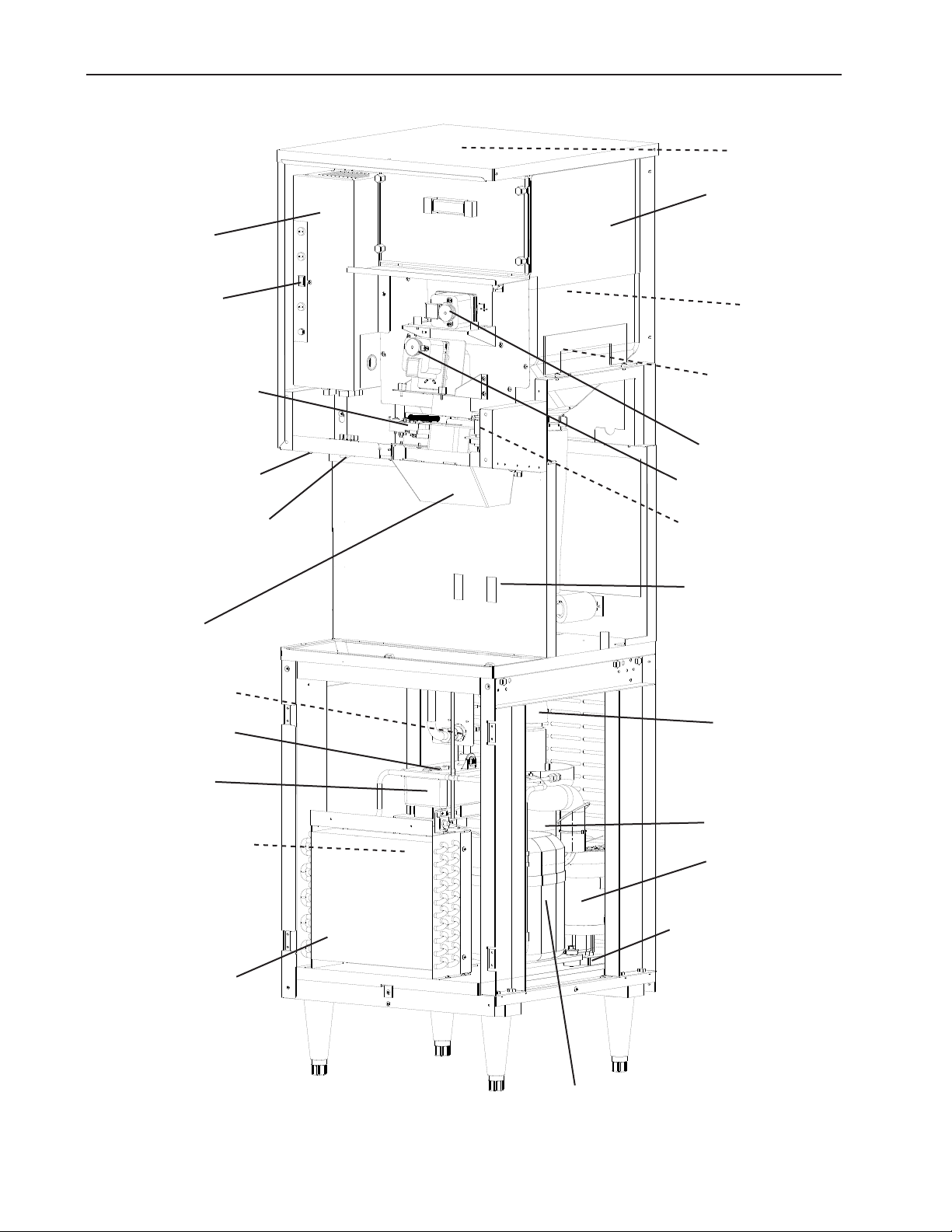
A. Construction
Control Box
Power Switch
Shutter Assembly
Control Switch
Dispense Mode Switch
Bin Control
Storage Bin
Agitator
Ice Dispensing
Auger
Agitating Motor
Dispensing Motor
Dispensing Water
Valve
Dispense Controls
Spout Cover
Inlet Water Valve
Float Switch
Reservoir
Drain Water Valve
Air-Cooled
Condenser
Transport Hose
Evaporator
Gear Motor
Gear Motor
Drain Pan
Compressor
6
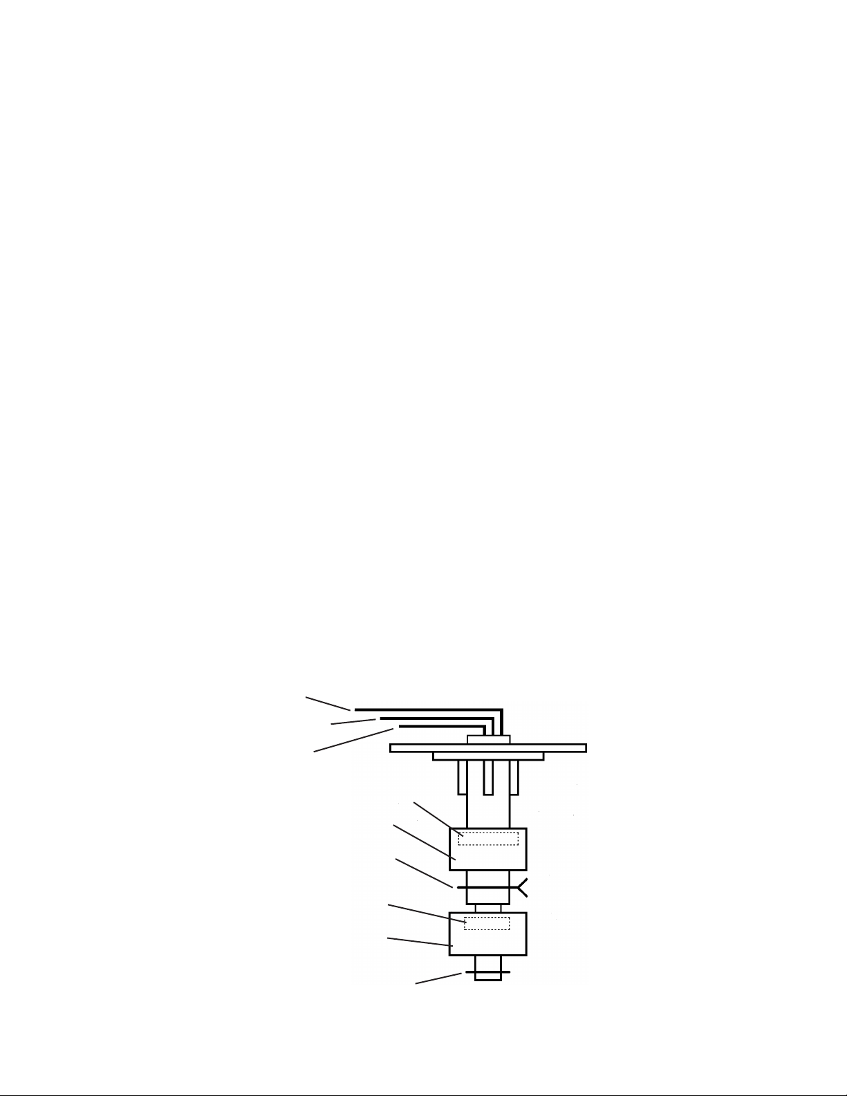
B. Ice Making Unit
Auger Cap
Extruding Head
Upper Bearing
O-Ring
Drain Pan
Auger
Evaporator
Cylinder
Mechanical-Seal
Auger Sleeve
Allen Head Cap Screw
Insulation
O-Ring
Housing-Lower Bearing
Spline Coupling
Allen Head Cap Screw
Hex Head Bolt
Gear Motor
7

C. Sequence of Operation
The steps in the sequence are as outlined below. When power is supplied, the power
switch is in the "ON" position, and the control switch is in the "ICE" position, the
"POWER" LED on the control board comes on.
1. Fill Cycle
WV opens and the reservoir lls with water until UF/S closes. Note: GM will not start
unless UF/S is closed. For details, see "IV. Service Diagnosis".
2. Ice Purge Cycle (60 seconds)
"GM" LED is on. WCR energizes, closing the low water safety circuit and de-energizing
the WV. GM and GMPR energize. GM runs for 60 seconds to clear any ice from the
evaporator.
3. Freeze Cycle
"COMP", "GM" LEDs are on. Comp and FMS energize. As the water in the evaporator
cools, ice starts forming within 4 to 6 minutes. This time frame depends on the inlet
water and ambient temperature conditions. UF/S and LF/S operate WV as needed to
continue the ice making process. This continues until BC shuts the icemaker down or
power is turned off to the icemaker.
4. Drain Cycle
1 hour DT activates, "FLUSH" LED is on after 150 second shutdown sequence. Comp
and FMS de-energize 90 seconds after the 1 hour DT activates, GMPR and GM
de-energize 60 seconds later. DV then energizes and remains energized for 0 minutes.
5. Shutdown
BC is activated and a 150 second shutdown sequence begins. After BC has been
open for 90 seconds, Comp and FMS de-energize, AM energizes for 0.6 seconds, and
60 seconds later GM de-energizes.
Legend: AM–agitating motor; BC–bin control; Comp–compressor; DT–drain timer;
FMS–self-contained fan motor; GM–gear motor; GMPR–gear motor protect
relay; LF/S–lower oat switch; UF/S–upper oat switch; WCR–water control
relay; WV–inlet water valve
8
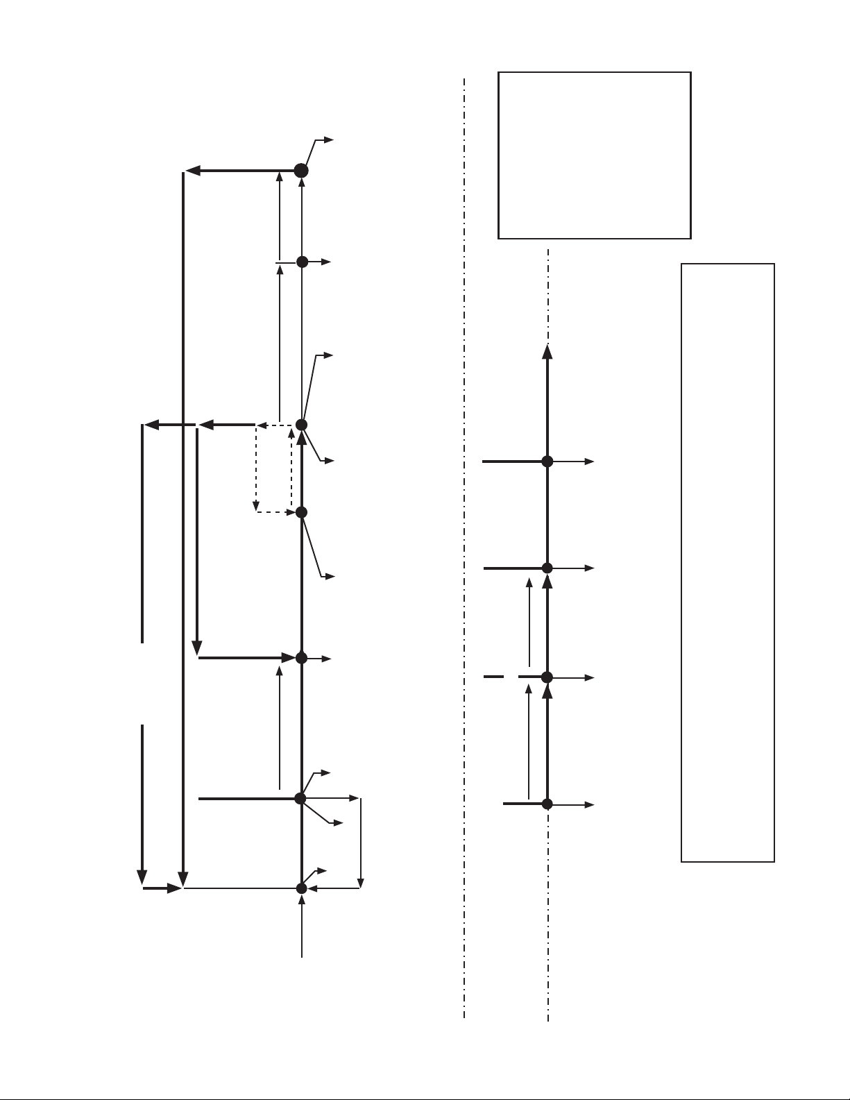
60 seconds
Low Water Safety
If rell > 90 sec. FT, 150 second
shutdown sequence begins
3. Freeze Cycle
90 seconds
150 sec. Shutdown Sequence
Rell
(90 seconds)
GM off
GMPR off
WV continues until
UF/S closes
Comp off
FMS off
WV continues
GM continues
GMPR continues
UF/S open
FT exceeded
Comp continues
FMS continues
GM continues
LF/S closed
UF/S closed (WV off)
WCR on
FT off (90 sec.)
WV off
UF/S open
LF/S open (WV on)
WCR off
FT started (90 sec.)
WV on
GMPR continues
WV continues
Comp continues
FMS continues
GM continues
Comp continues
FMS continues
GM continues
GMPR continues
GMPR continues
Legend:
BC - bin control
Comp - compressor
DC - drain cycle
DT - drain timer
DV - drain valve
FMS - self-contained fan motor
FT - ll timer (low water safety)
4. Ice Level Lowered
See "1. Fill Cycle" above
3. Icemaker is Off
4. 12 hour DC - Restart
See "1. Fill Cycle" above
BC closedor20 Min. DT off (DC only)
3. Drain Cycle
DV on for 20 minutes
GM off
GM - gear motor
GMPR - gear motor protect relay
LF/S - lower oat switch
UF/S - upper oat switch
DV off (DC only)
12 hour DT reset (DC only)
GMPR off
DV on (DC only)
WCR - water control relay
WV - inlet water valve
60 seconds
2. Ice Purge Cycle
150 seconds
1. Bin Full
4. Drain Cycle
2. Ice Purge Cycle
DV opens for 0 minutes every 1 hours
See "3. 1 Hour Drain Cycle" below.
Comp on
60 seconds
LF/S closed
FMS on
WCR continues
GM continues
GMPR continues
UF/S closed (WV off)
WCR on
WV off
GM on
GMPR on
DT-400BAH-OS Sequence Flow Chart and Component Operation
UF/S open
1. Fill Cycle
WV on
2. Ice Purge Cycle
90 seconds
1. Drain Cycle initiates
Comp off
FMS off
Comp continues
BC open or DC starts
GM continues
GMPR continues
FMS continues
GM continues
GMPR continues
Components Energized when the Control Switch is in the "DRAIN" Position
Shutdown & Restart
1. Startup
Power switch "ON"
Control switch in "ICE"
2. Shutdown & Restart
3. 12 Hour Drain Cycle
9
The "DRAIN" position on the control switch is used when cleaning and sanitizing the unit. This allows cleaner and
sanitizer to drain from the reservoir and evaporator assembly. When switching to the "DRAIN" position during the freeze
cycle, the drain valve does not energize until the 150 second shutdown sequence terminates (. Shutdown & Restart).
Note: To bypass the 150 second shutdown sequence, move the power switch to the "OFF" position, place the
control switch in the "DRAIN" position, then move the power switch back to the "ON" position.

D. Control Board
• A Hoshizaki exclusive solid-state control board is employed in DT-400BAH-OS Cubelet
Icemaker / Dispenser.
• All models are pretested and factory-adjusted.
CAUTION
1. Fragile, handle very carefully.
. The control board contains integrated circuits, which are susceptible to
failure due to static discharge. It is especially important to touch the metal
part of the unit before handling or replacing the board.
3. Do not touch the electronic devices on the control board or the back of the
control board to prevent damage to the control board.
4. Do not change wiring and connections. Especially, never misconnect
terminals.
5. Always replace the whole control board if it goes bad.
6. Do not short out power supply to test for voltage.
10
1. Control Board Layout
DT-400BAH-OS
Flush Switch
Must be left in the "P" position,
otherwise the internal drain
timer will not operate.
Counter Reset Button (not
used in this application)
Dispensing Components
See "III.B. Wiring Diagram"
for details.
Bin Control,
Control Switch,
Low Water Safety
High
Pressure
Switch
10.5V
Transformer
Portion Control
Timer
"FLUSH" LED
(X6 Relay)
Drain Valve
4V Supply Out
Drain Valve
4V Out
"WTR" LED
(X5 Relay)
Dispensing
Water Valve
4V In
Dispensing
Water Valve
4V Out
Microprocessor (board revision level
indicated by last digits on label)
"ICE" LED
(X4 Relay)
Shutter Solenoid,
Dispensing Auger
Motor
4V In
Dispensing Motor
115V Out
115V In
"AM" LED
(X3 Relay)
Agitating Motor
"COMP" LED
(X Relay)
Compressor,
Fan Motor
115V In
Agitating Motor
115V Out
"POWER" LED
(lights when
power is supplied
to the board)
"GM" LED
(X1 Relay)
Gear Motor
Gear Motor
Protect Relay
Circuit
115V In
Gear Motor
115V Out
Control Board
Part Number A649-01
11
2. Features
The control board provides the following safeguards:
• Provides component protection during low water supply.
• Purges remaining ice in the evaporator at startup and shutdown.
• Provides short cycle protection for the compressor.
a) LED Lights
The "POWER" LED indicates control voltage and will remain on unless a control
voltage problem occurs. An LED illuminates for each relay as it is energized. For more
information, see "II.C. Sequence of Operation."
Icemaking
Cycle (Relay) LED
Fill POWER only WV N/A As Needed
Ice Purge (X1) GM GM 60 seconds N/A
Freeze (X1, X)
Drain Valve (X6) FLUSH DV 0 Minutes Every 1 Hours
Relay LED
Ice Dispense (X4) ICE IDM
Agitating Motor (X3) AM AM .6 seconds
Water Dispense (X5) WTR WTR N/A N/A
GM, COMP GM, Comp, FMS N/A N/A
Energized
Components
Dispensing
Energized
Component
Time LEDs are OnFrequency LEDs are
On
Time LEDs are OnFrequency LEDs are
On
60 seconds
maximum
N/A
Every 1 seconds of
accumulative dispense
time
Legend: AM–agitating motor, Comp–compressor; DV–drain valve; FMS–self-contained
fan motor;
GM–gear motor; IDM–ice dispensing motor, shutter solenoid;
WTR–dispensing water valve; WV–inlet water valve
1
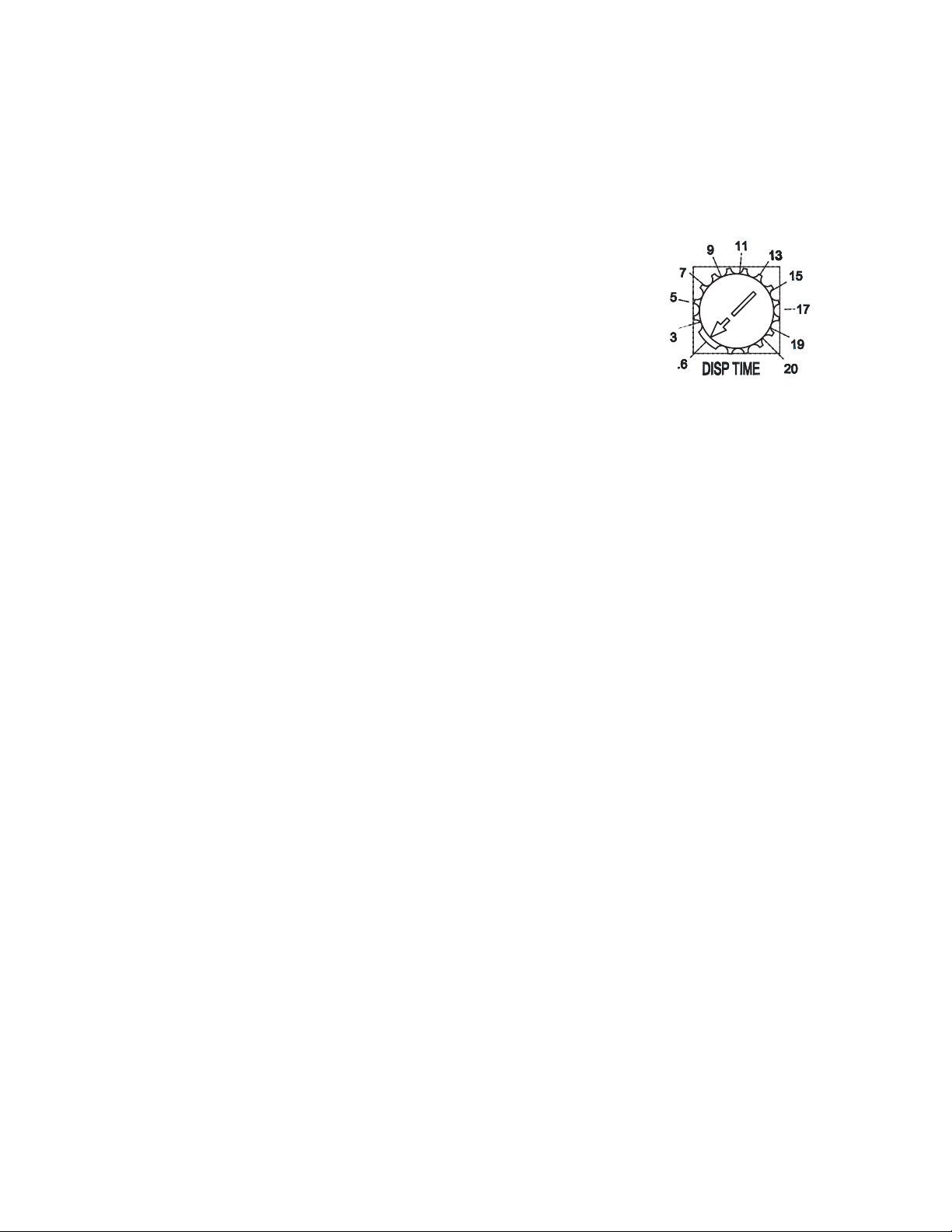
3. Controls and Adjustments
a) Portion Control
When the change switch (dispense mode switch) is placed in the "PORTION" position, a
variable resistor (located on the control board) controls the ice dispense time.
The gures on the label indicate dispensing time (sec.). When shipped, the portion
control is set at the minimum dispensing time (0.6 sec.).
DT-400BAH-OS . . . . . . . . . . . . Approximately 0.7 oz.
Amount of ice dispensed per second.
DT-400BAH-OS . . . . . . . . . . . . Approximately 1. oz.
4. Control Board Check Procedure
Before replacing a control board that does not show a visible defect and that you suspect
is bad, always conduct the following check procedure. This procedure will help you verify
your diagnosis.
a) Power Supply
1. Move the control switch to the "ICE" position. The "POWER" LED should come on.
If the "POWER" LED is off, check that the power supply is on, the power switch is in
the "ON" position, the safety switch is not engaged, and the control switch is in the
"ICE" position. Check the transformer 10.5V secondary circuit and fuse. If the 10.5V
secondary circuit (K4 pins 1 and ) has proper voltage and the "POWER" LED is off,
the control board is bad and should be replaced.
If the secondary circuit does not have proper voltage, see "IV.C.1.[1] The icemaker will
not start (Fill Cycle)" for further details.
b) Ice Making Components
1. Conrm the reservoir is full of water. If no water is in the reservoir, make sure that the
control switch is not in the "DRAIN" position and that the unit is not in the 1 hour drain
cycle. Also check the water supply line, water shutoff valve, and water lters. In the ll
cycle, the "POWER" LED will be the only LED lit on the control board. If no water is
lling the reservoir, check for 4V at connector K terminal 7 to neutral and connector
K3 (DBU) to neutral. If there is 4V at connector K terminal 7 to neutral and no voltage
at K3 (DBU) to neutral, the control board is bad and should be replaced. See "IV.C.1.[1]
The icemaker will not start (Fill Cycle)" for further details.
. When the reservoir is full, the "GM" LED comes on and the gear motor starts. If the
"GM" LED does not come on or the gear motor does not start, check that the following
safety circuits are closed: a) high pressure switch (connector K4 terminals 5 and 6),
b) low water safety/bin control/ice making switch circuit (connector K4 terminals
3 and 4). Next, check for 115/10V at connector K1 "COM" and K1 "NO" on the control
board to neutral. If the "GM" LED is on and there is voltage at connector K1 "COM" to
neutral and no voltage at K1 "NO" to neutral, the control board is bad and should be
replaced. See wiring diagram "III.C.. Ice Purge Cycle" for further details.
13
3. 60 seconds after the "GM" LED comes on, the "COMP" LED comes on, and the
compressor and fan motor start. If the "COMP" LED does not come on 60 seconds
after the gear motor starts, check that the gear motor protect relay contacts (connector
K terminals 1 and ) have closed. If the "COMP" LED is on and the compressor and
fan motor did not start, check for 115/10V at X (LBU) and X (BR) on the control
board to neutral. If the "COMP" LED is on and there is voltage at X (BR) to neutral
and no voltage at X (LBU) to neutral, the control board is bad and should be replaced.
See wiring diagram "III.C.3. Freeze Cycle" for further details.
c) Dispensing Components
See "IV.C.5. Opti Serve (OS) Sensors."
E. Float Switch
Depending on local water conditions, scale may build up on the oat switch. Scale on the
switch can cause the oats to stick. In this case, the oat switch should be cleaned and
checked.
First, remove the switch from the water tank. Soak the switch assembly in ice machine
cleaner. While not necessary, the oats can be removed from the shaft during cleaning.
If you remove them, note that the blue oat is on top. The oats must be installed with
the magnets inside them towards the top of the switch. Installing the oats upside down
will affect the timing of the oat switch operation. Once clean, rinse and wipe the cleaner
off. Next, check the switch with an ohm meter. This oat switch has three wires (the
black wire is common) and two separate switches. Check the upper switch by ohming
out the black and red wires. When the oat is up, the switch should be closed. Check the
lower switch by ohming out the black and blue wires in the same manner. If either switch
fails, the assembly should be replaced.
Red (upper)
Black (common)
Blue (lower)
Magnet (towards top)
Upper Float (blue)
Spring Retainer Clip
Magnet (towards top)
Lower Float (white)
Plastic Retainer Clip
14
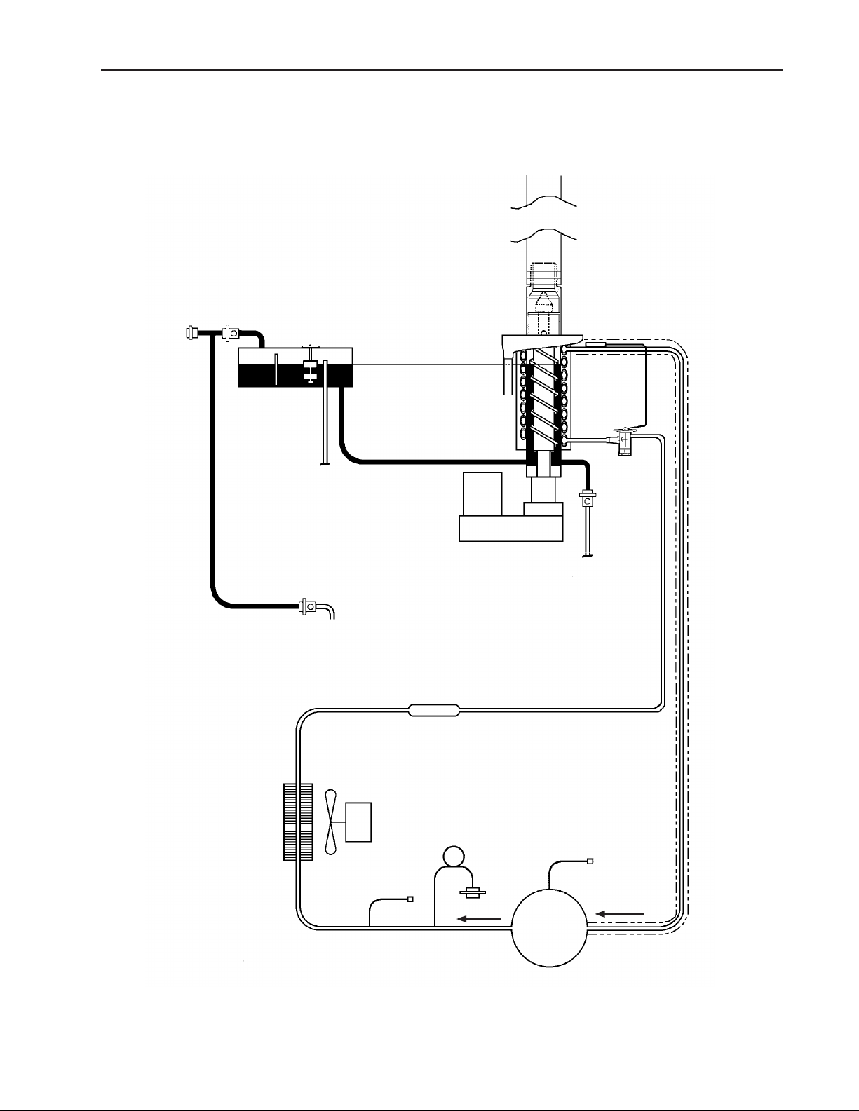
III. Technical Information
A. Water Circuit and Refrigeration Circuit
1. DT-400BAH-OS
Transport Hose
Water Supply
Inlet Water Valve
Float Switch
Reservoir
Overow
Dispensing Water Valve
Water Level
Gear Motor
Drier
Drain Pan
To Drain
Evaporator
Expansion
Valve
Drain
Valve
To Drain
Condenser
Condenser
Fan Motor
Access Valve
15
High
Pressure
Switch
Compressor
Access Valve
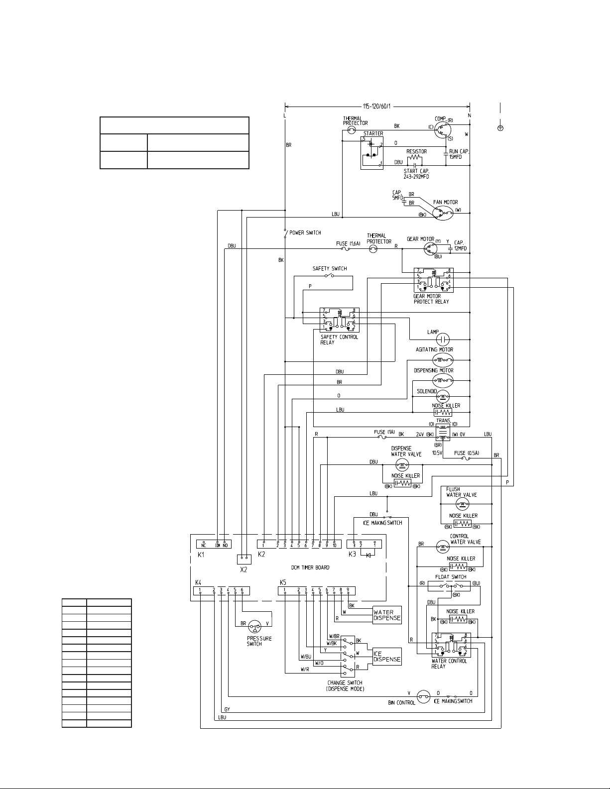
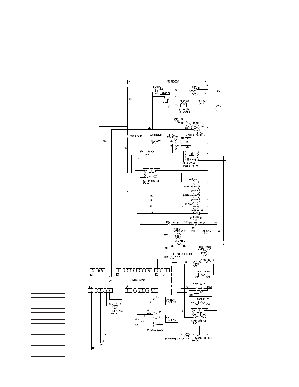
B. Wiring Diagram
1a. DT-400BAH-OS (auxiliary code: S-0)
* High Pressure Switch
GND
Cut-out 412±21 PSIG
0
Cut-in 327±21 PSIG
WIRE COLOR CODE
BK BLACK
BR BROWN
BU BLUE
DBU DARK BLUE
GY GRAY
LBU LIGHT BLUE
O ORANGE
P PINK
R RED
V VIOLET
W WHITE
Y YELLOW
W/BK WHITE/BLACK
W/BR WHITE/BROWN
W/BU WHITE/BLUE
W/O WHITE/ORANGE
W/R WHITE/RED
*
16
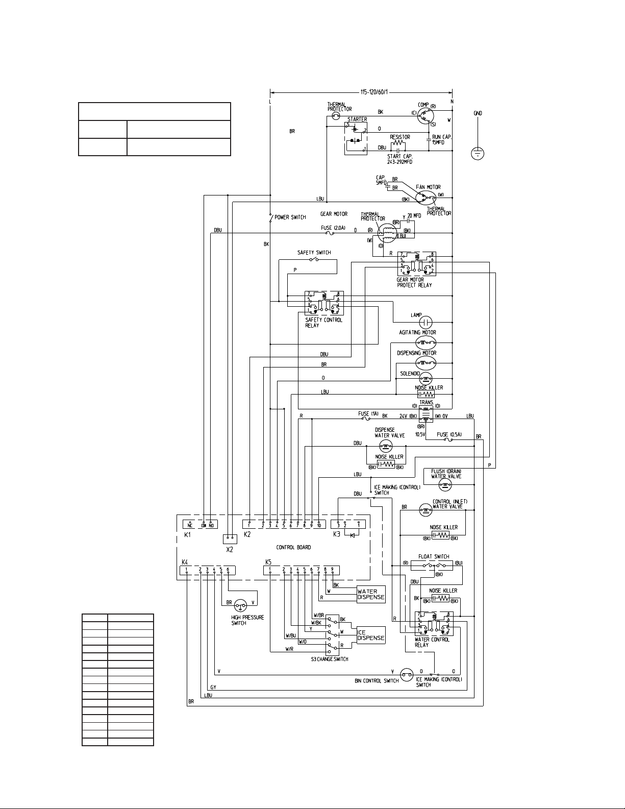
1b. DT-400BAH-OS (auxiliary code: T-0 and later)
* High Pressure Switch
Cut-out 412±21 PSIG
0
Cut-in 327±21 PSIG
WIRE COLOR CODE
BK BLACK
BR BROWN
BU BLUE
DBU DARK BLUE
GY GRAY
LBU LIGHT BLUE
O ORANGE
P PINK
R RED
V VIOLET
W WHITE
Y YELLOW
W/BK WHITE/BLACK
W/BR WHITE/BROWN
W/BU WHITE/BLUE
W/O WHITE/ORANGE
W/R WHITE/RED
*
17
C. Sequence of Electrical Circuit – Ice Making (auxiliary code T-0 and
later)
1. Fill Cycle
With the power switch in the "ON" position and the control switch in the "ICE" position,
the inlet water valve energizes and the reservoir lls with water until the upper oat
switch closes.
WIRE COLOR CODE
BK BLACK
BR BROWN
BU BLUE
DBU DARK BLUE
GY GRAY
LBU LIGHT BLUE
O ORANGE
P PINK
R RED
V VIOLET
W WHITE
Y YELLOW
W/BK WHITE/BLACK
W/BR WHITE/BROWN
W/BU WHITE/BLUE
W/O WHITE/ORANGE
W/R WHITE/RED
DT-400BAH-OS
18
 Loading...