

Hoshizaki America DT-400BAH-OS Parts List

Hoshizaki America, Inc.
Hoshizaki
Cubelet Icemaker/Dispenser
Model
DT-400BAH-OS
“A Superior Degree
of Reliability”
www.hoshizaki.com
PARTS LIST
Number:
Issued: 1-20-2011
71273

CONTENTS
Auxiliary Codes ...................................................................................................................... 3
Note About Ordering Parts .................................................................................................... 3
Material Abbreviations ........................................................................................................... 4
A. Flaker Dispensing Assembly ............................................................................................. 5
B. Ice Flaker Assembly .......................................................................................................... 8
C. Dispenser Assembly ........................................................................................................ 12
D. Water Circuit - Dispense .................................................................................................. 15
E. Cabinet Stand Assembly ................................................................................................. 19
F. Label Location .................................................................................................................. 21
G. Refrigeration Circuit ........................................................................................................ 23
H. Water Circuit - Ice Making ............................................................................................... 27
J. Ice Making Unit ................................................................................................................ 29
K. Control Box Assembly...................................................................................................... 30
L. Middle Front Frame Assembly .......................................................................................... 33
M. Apron Panel Assembly .................................................................................................... 34
N. Bin Assembly ................................................................................................................... 35
P. Gear Motor Assembly - Agitate ......................................................................................... 37
Q. Gear Motor Assembly - Dispense ................................................................................... 38
R. Shutter Assembly ............................................................................................................ 39
S. Evaporator Unit ................................................................................................................ 41
T. Accessories and Packaging ............................................................................................. 43
2

Auxiliary Codes
DT-400BAH-OS S-0 July 2007
T-0 March 2008
V-1 June 2010
V-2 December 2010
A-0 January 2011
Auxiliary Code Breakdown
The auxiliary code is the rst two characters in the serial number. The rst character
indicates the year. Years progress or regress in alphabetical order. The series runs from
"A" through "V" and the letters "I" and "O" are skipped. The second character indicates
signicant part changes within a year. Base is "0" and this number advances for each
change. In cases where there is a letter in parentheses, this designates the month. This is
the last character in the serial number. The series runs from "(A)" through "(M)" and the
letter "(I)" is skipped. This designation is only included when identifying a parts change
within an auxiliary code.
Note About Ordering Parts
Most assemblies cannot be ordered as complete units; parts in the assemblies generally
must be ordered separately.
3

Material Abbreviations
ALUMINUM
AL = Aluminum
COPPER
CU = Copper
PLASTIC
ABS = Acrylonitrile -butadiene - styrene
AC = Polyacetal
EVA = Ethylene vinyl acetate
PA = Polyamide = Nylon
PC = Polycarbonate
PE = Polyethylene
PES = Polyester
PETP = Polyethylene terephthalate = Tetlon
PP = Polypropylene
PS = Polystyrene
PTFE = Polytetrauoroethylene = Teon
PUR = Polyurethane
PVC = Polyvinyl chloride
RUBBER
VN = Vinyl Nitrile
EPDM = EP rubber
NBR = Nitrile butadiene rubber
NR = Natural rubber
NP = Neoprene
SI.R = Silicone rubber
SY.R = Synthetic rubber
EPH = Epichlorohydrin
STEEL
GS = GSanized steel
SS = Stainless steel
PS = Plated steel
PAS = Primed steel
4
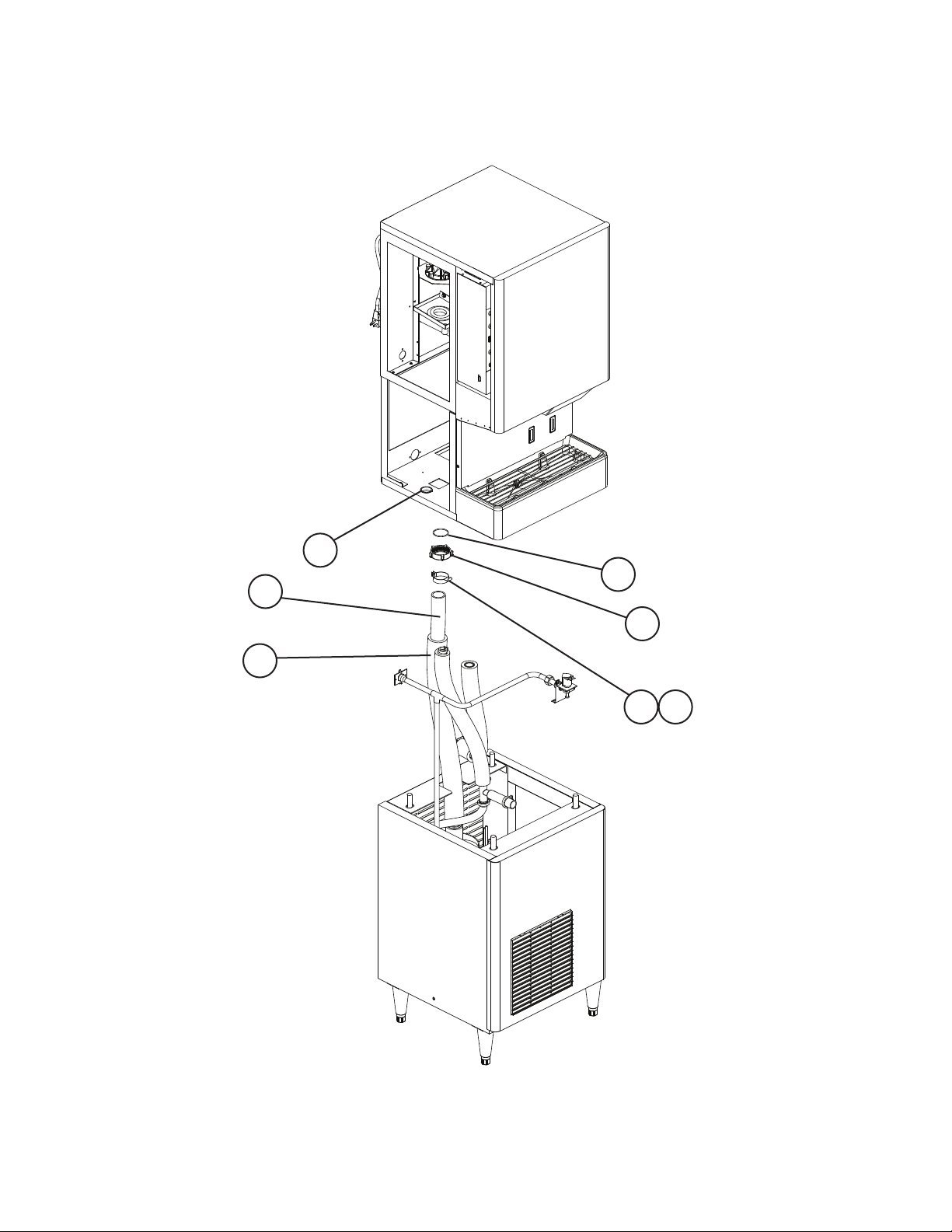
A. Flaker Dispensing Assembly
1/2
DT-400BAH-OS
S-0 to A-0
D
F
C
C1 C2
E
6
8
B
6a
Note: For panels, see "C. Dispenser Assembly" and "E. Cabinet Stand Assembly".
5
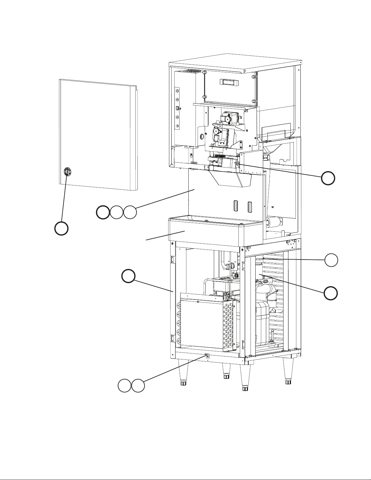
A. Flaker Dispensing Assembly
2/2
DT-400BAH-OS
S-0 to A-0
7
5
1
4
2
3a
3
Note: For panels, see "C. Dispenser Assembly" and "E. Cabinet Stand Assembly".
6

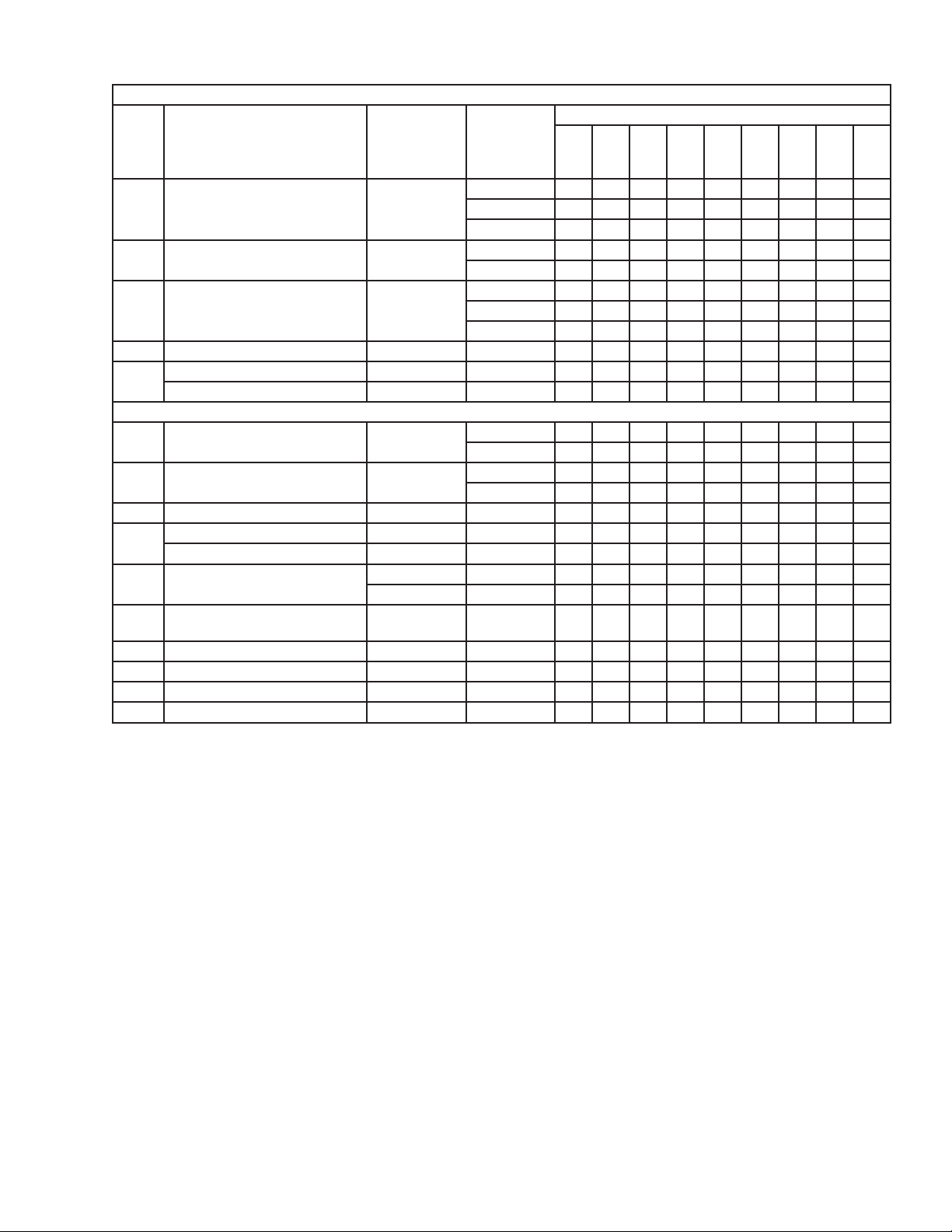
Title: A. Ice Flaker Assembly Model: DT-400BAH-OS
Index
No. Description
B Ice Flaker Assembly - 2A4216A01 1 -
C Dispenser Assembly - 1A1258A01 1 -
C1 Flat Washer 5/8" 7W21I5800 4 4 4
C2 Hex Bolt 5/8-11UNC×1
D Water Circuit-Dispense - 2A4102A01 1 -
E Cabinet Stand Assembly - 2A4121A01 1 -
F Label Location - 2A4188A01 1 -
1 Reinforced Hose L=1090 4A4299-01 1 1 1
2 Insulation Tube L=915 4A4289-01 1 1 1
3 Band (A) - 4A4178G01 1 -
3a Truss Head Screw 4×12, SS 7C32-0412 1 1 1
4 Slip Nut - 3A4339-01 1 1 1
5 "O"-Ring - 4A4298-01 1 1 1
6 Strap - 4A4301-01 1 1 1
6a FT Screw 4×8, SS 7F32-0408 1 1 1
7 Bushing SB-1500-21 420470-06 2 2 2
8 Clamp - 4A2532-01 1 1 1
Material or
Model Number Part Number
2A4507A01 1 2A6037A01 1
1A1493A01 1 1A2039A01 1
7B01I5810 4 4 4
1/4"
2A4520A01 1 1
2A4511A01 1 1
2A4522A01 1 2A6040A01 1
4A4440G01 1 1
S-0 T- 0
Required Number
V-1
to
A-0
7
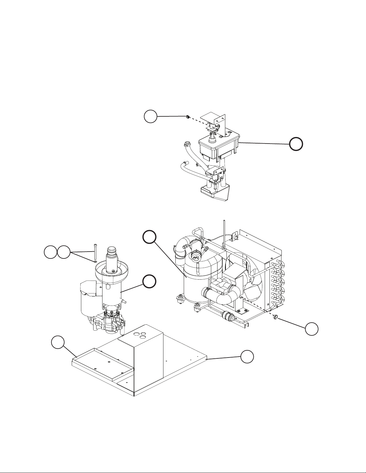
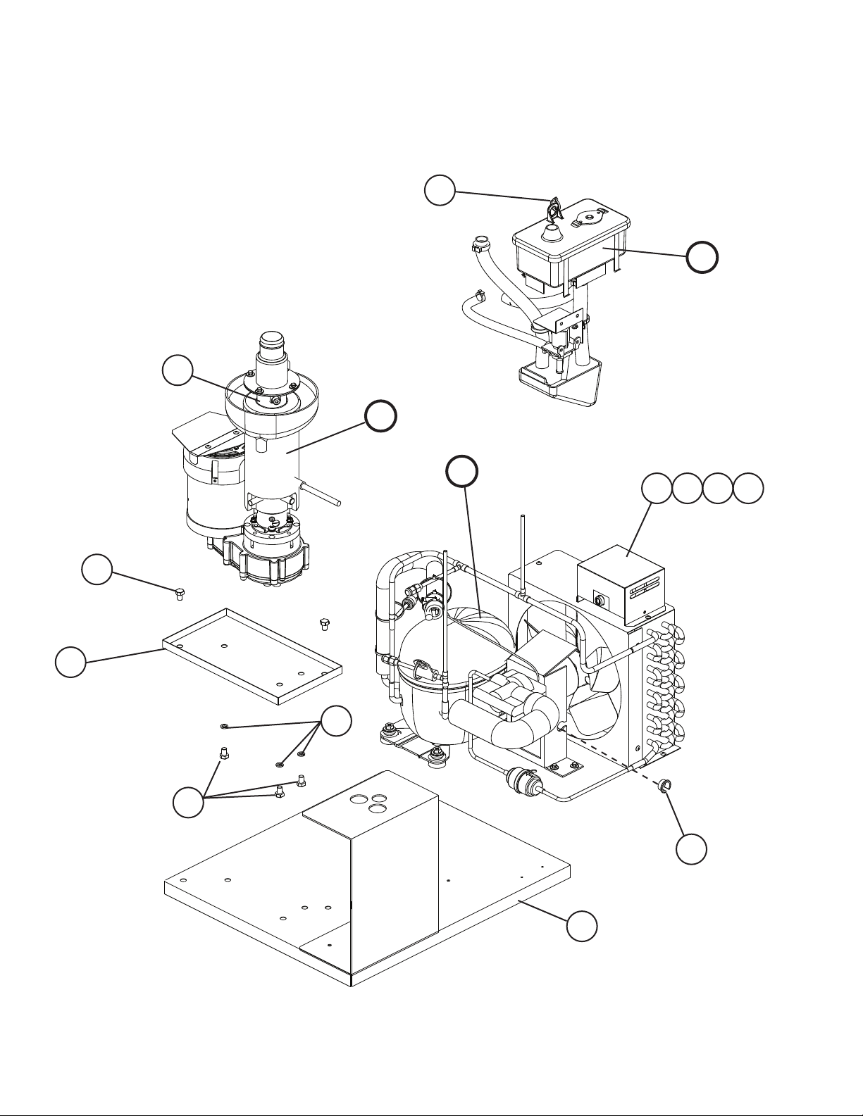
B. Ice Flaker Assembly
DT-400BAH-OS
S-0
3
H
J1
G
J2
J
4
2
1
8
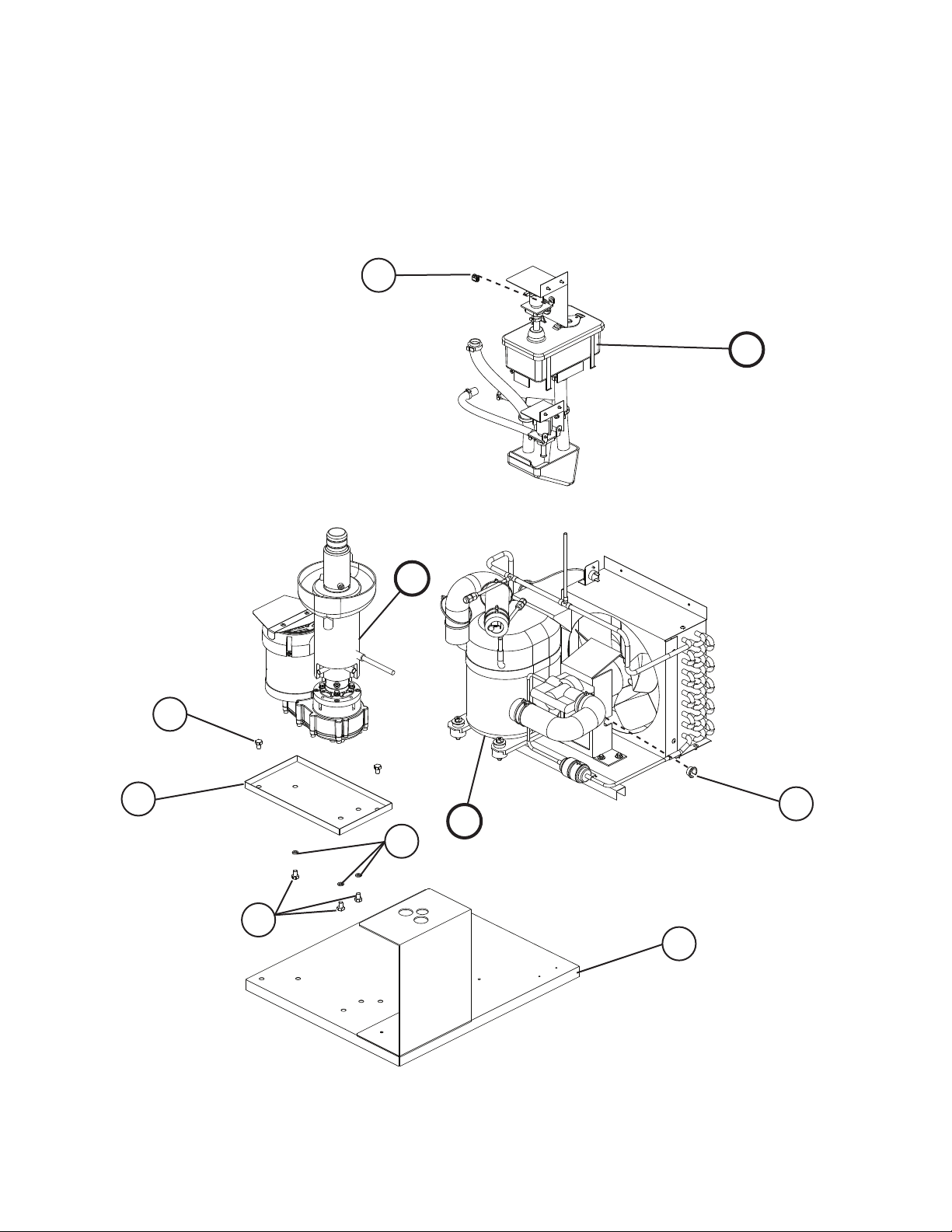
B. Ice Flaker Assembly
DT-400BAH-OS
T- 0
3
H
J
2a
2
4
G
J1
J2
1
9
B. Ice Flaker Assembly
DT-400BAH-OS
V-1 to A-0
7
J
3
H
G
5a
5
6a
6
2a
2
J1
J2
4
1
10
Title: B. Ice Flaker Assembly Model: DT-400BAH-OS
Index
No. Description
G Refrigeration Circuit - 2A1870A01 1 -
H Water Circuit-Icemaking - 2A1874A01 1 -
J Ice Making Unit - 3A1830A01 1 -
J1 Split Lock Washer M8, SS 7L22-0800 3 3 3
J2 Socket Hex Head Bolt 8×80, SS 7S12-0880 3 -
Hex Head Bolt 8×12 7B02-0812 3 3
1 Base-(A) - 2A1863G01 1 -
2 Drain Pan - 4A2576-01 1 -
2a Hex Head Bolt 8×12 7B02-0812 2 2
3 Bushing SR-30-1 420472-03 1 1 -
Cable Tie - 8911-0100 1
4 Bushing OCB-875 428394-04 1 -
5 Transformer Box (includes
items 6 and 6a)
5a T2 Screw 4×8 7P31-0408 1
6 Transformer (Belt Heater) 4A0557-01 1
6a T2 Screw 4×8 7P31-0408 2
7 Belt Heater - 4A4375-01 1
Material Or
Model Number Part Number
2A4508A01 1 2A6041A01 1
2A4509A01 1 1
3A4720A01 1 3A6046A01 1
2A4506G01 1 1
4A4435-01 1 1
OCB-750 428394-01 1 1
- 2A6048A01 1
S-0 T- 0
Required Number
V-1
to
A-0
11
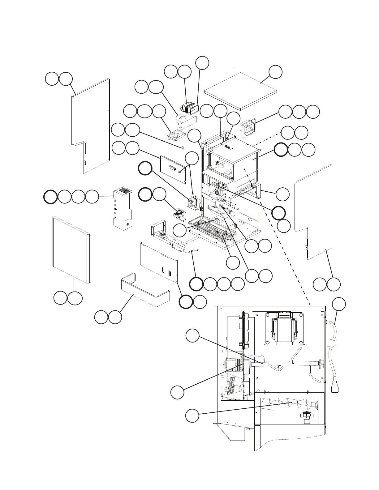
C. Dispenser Assembly
DT-400BAH-OS
S-0 to A-0
5a
5
13
13a
11
8
28
7
K
K1 K2
K3
21
16
20
21a
17
20a
Q
R
25
R1
23
30
29
L
26
L1
31
L2
24
22
30
27
14
10 27
P
N
29
9
3
N1
1
12
3a
N2
27
4a
4
2a
2
6a
6
17
M
18
19
12
M1
15

Title: C. Dispenser Assembly Model: DT-400BAH-OS
Index
No. Description
K Control Box Assembly - 3A4189A01 1 -
K1 Truss Head Screw 4×8, SS 7C32-0408 1 1 1
K2 Flat Head Screw 4×12, SS 7C22-0412 2 2 2
K3 Taper Collar SS 4H0171-01 2 2 2
L Middle Front Frame Assembly - 2A3972A01 1 1 1
L1 Flat Head Screw 4×12, SS 7C22-0412 2 2 2
L2 Taper Collar SS 4H0171-01 2 2 2
M Apron Panel Assembly - 3A4183A01 1 1 1
M1 Truss Head Screw 4×8, SS 7C32-0408 4 4 4
N Bin Assembly - 2A0413A01 1 1 1
N1 Truss Head Screw 4×12 7C31-0412 2 2 2
N2 Truss Head Screw 4×8, SS 7C32-0408 3 3 3
P Gear Motor Assembly-Agitate - 4A0620A01 1 1 1
Q Gear Motor Assembly-Dispense - 4A0622A01 1 1 1
R Shutter Assembly - 2A0410A01 1 1 1
R1 Truss Head Screw 4×8, SS 7C32-0408 2 2 2
Material or
Model Number Part Number
3A4726A01 1 3A6055A01 1
S-0 T- 0
Required Number
V-1
to
A-0
1 Frame - 2A3967A01 1 -
2A4517A01 1 1
2 Front Panel - 3A4186G01 1 1 1
2a Truss Head Screw 4×8, SS 7C32-0408 1 1 1
3 Rear Panel - 2A3989-01 1 1 1
3a Truss Head Screw 4×8, SS 7C32-0408 2 2 2
4 Side Panel (R) SS 2A2625-01 1 1 -
2A6141-01 1
4a Truss Head Screw 4×8, SS 7C32-0408 6 6 6
5 Side Panel (L) SS 2A2624-01 1 1 -
2A6142-01 1
5a Truss Head Screw 4×8, SS 7C32-0408 6 5 5
6 Panel (LO) - 2A3977G01 1 1 1
6a FT Screw 4×8, SS 7F32-0408 6 6 6
7 Top Panel - 3A4188G01 1 1 1
8 Spout - 2A4108-01 1 1 1
9 Spout (B) - 208807-01 1 1 1
10 Spout Cover - 215773-01 1 1 1
11 Packing (A)-Spout - 427195-01 1 1 1
12 Packing (B)-Spout - 427196-01 1 1 1
13 Spout Flange (A) - 4A4140-01 1 -
4A4446-01 1 1
13a Hex Bolt w/Washer (LF) 5×12, SS 7B0230512 2 2 2
14 Ice Chute - 4A2204-01 1 1 1
15 Power Cord - 4A1543-01 1 1 1
16 Bin Cover - 2A0880A02 1 1 1
17 Gasket - 429758-01 1 1 2
13
 Loading...