

Page 1
Hoshizaki
Hoshizaki America, Inc.
Commercial Refrigerator
Roll-In Series
Model
RIR1-SSB
“A Superior Degree
of Reliability”
www.hoshizaki.com
PARTS LIST
Number: 71295
Issued: 1-19-2009
Page 2

CONTENTS
Auxiliary Codes ...................................................................................................................... 3
Note About Ordering Parts .................................................................................................... 3
Material Abbreviations ........................................................................................................... 4
A. Roll-In Assembly ................................................................................................................ 5
B. Refrigeration Circuit ........................................................................................................... 7
C. Control Box Assembly ......................................................................................................11
D. Control Panel Group ........................................................................................................ 12
E. Light Group ...................................................................................................................... 13
F. Upper Panel Group .......................................................................................................... 14
G. Interior Group .................................................................................................................. 16
H. Door-Right ....................................................................................................................... 17
J. Evaporator Assembly ....................................................................................................... 19
K. Evaporator Fan Assembly ................................................................................................ 20
L. Condenser Assembly ....................................................................................................... 21
M. Common Control Box ...................................................................................................... 23
N. Door Subassembly-Right ................................................................................................ 25
P. Accessories & Packaging ................................................................................................. 26
2
Page 3

Auxiliary Codes
RIR1-SSB T-5 June 2008
U-5 January 2009
Auxiliary Code Breakdown
The auxiliary code is the rst two characters in the serial number. The rst character
indicates the year. Years progress or regress in alphabetical order. The series runs from
"A" through "V" and the letters "I" and "O" are skipped. The second character indicates
signicant part changes within a year. Base is "5" and this number advances for each
change.
Note About Ordering Parts
Most assemblies cannot be ordered as complete units; parts in the assemblies generally
must be ordered separately.
3
Page 4

Material Abbreviations
ALUMINUM
AL = Aluminum
COPPER
CU = Copper
PLASTIC
ABS = Acrylonitrile -butadiene - styrene
AC = Polyacetal
EVA = Ethylene vinyl acetate
PA = Polyamide = Nylon
PC = Polycarbonate
PE = Polyethylene
PES = Polyester
PETP = Polyethylene terephthalate = Tetlon
PP = Polypropylene
PS = Polystyrene
PTFE = Polytetrauoroethylene = Teon
PUR = Polyurethane
PVC = Polyvinyl chloride
RUBBER
VN = Vinyl Nitrile
EPDM = EP rubber
NBR = Nitrile butadiene rubber
NR = Natural rubber
NP = Neoprene
SI.R = Silicone rubber
SY.R = Synthetic rubber
EPH = Epichlorohydrin
STEEL
GS = Galvanized steel
SS = Stainless steel
PS = Plated steel
PAS = Primed steel
4
Page 5
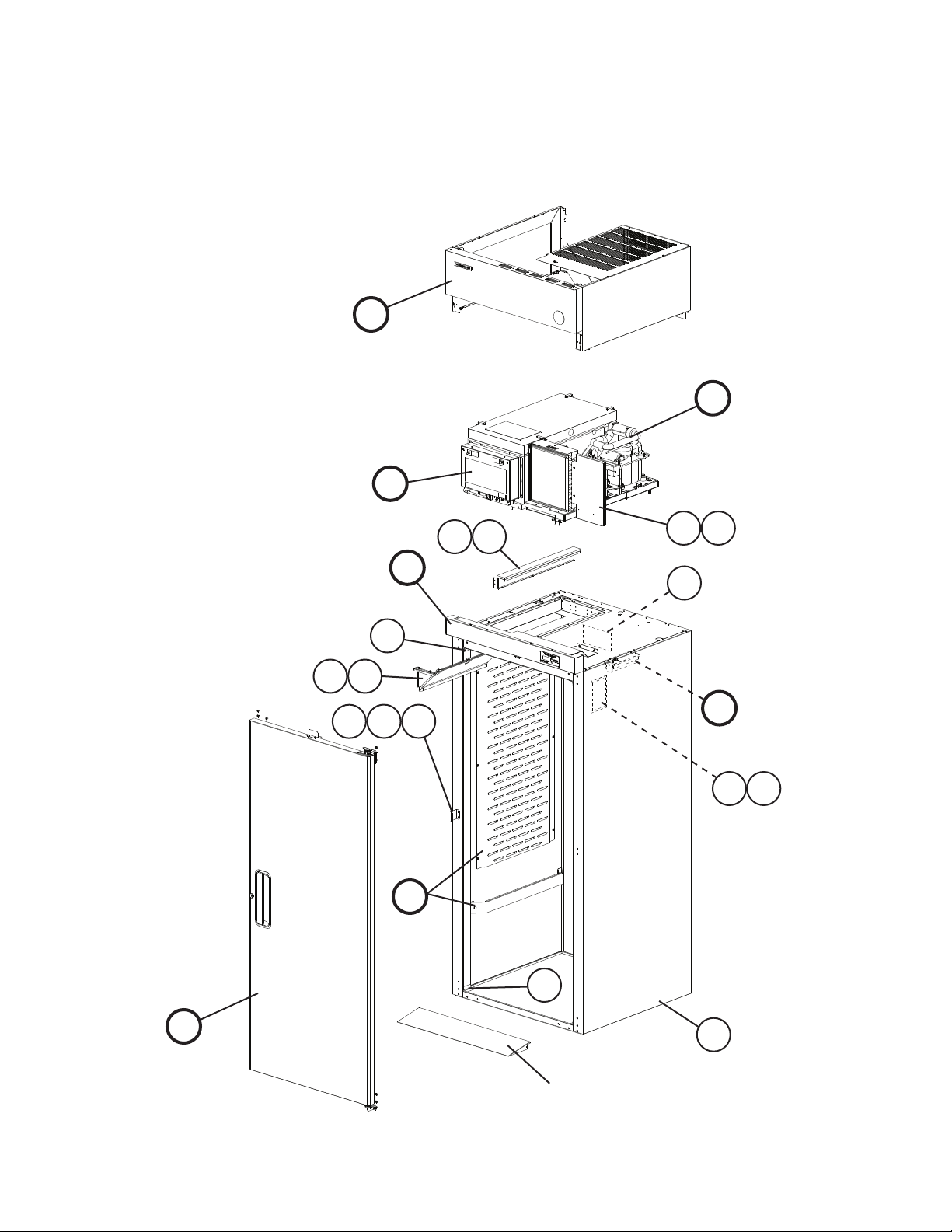
A. Roll-In Assembly
RIR1-SSB
T-5, U-5
F
C
B
4a
8a
8
4
D
9
2
7a
7
6a
6
5
E
10 11
G
3
H
1
For Ramp Group,
see section "P"
5
Page 6
Title: A. Roll-In Assembly Model: RIR1-SSB
Index
No. Description
B Refrigeration Circuit (For
mounting hardware, see
section "B" items 1 through 3)
C Control Box Assembly (For
mounting hardware, see
section "M" item 1)
D Control Panel Group (For
mounting hardware, see
section "D" item 1)
E Light Group (For mounting
hardware, see section "E" item
1a)
F Upper Panel Group (For
mounting hardware, see
section "F" item 1)
G Interior Group 2A4486A01 1
H Door-Right (For mounting
hardware, see section "H"
item 1)
1 Body 1A1490G01 1
2 Corner Cover 3A1751-01 2
3 Corner Cover-Shaved 3A4731G01 2
4 Block-Air GS 3A4730-01 1
4a T2 Screw 4×8, SS 7P32-0408 2
5 Strike Group (includes items 6
and 6a)
6 Strike Plate 4A4590-01 1
6a T2 Screw 4×8, SS 7P32-0408 2
7 Upper Air Distributor Group
(includes item 7a)
7a T2 Screw 4×8, SS 7P32-0408 7
8 Air Divider Group (includes
item 8a)
8a T2 Screw 4×8, SS 7P32-0408 4
9 Caution Label 4A1931-01 1
10 Nameplate 2A4523-01 1
11 Cover-Nameplate 4A3727-01 1
Material or
Model Number Part Number
1A1413A01 1
2A4381A01 1
3A4709A01 1
3A4735A01 1
2A4492A01 1
2A4759A01 1
4A4432A01 1
3A4526A01 1
3A4164A01 1
Required Number
T- 5
U-5
6
Page 7

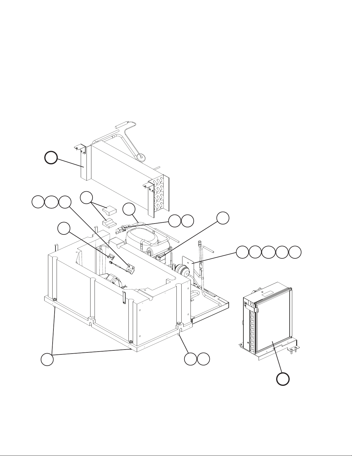
B. Refrigeration Circuit
1/2
RIR1-SSB
T-5, U-5
44
K
33
34
34a
30 31
14a
14
27 28
8a
8
9
29
42
7
39
19
36
43
40 41
38
35
35a
4
3
5
6a
6
15a 15b 15c 15d 15e
15
7
2
10 11 12 13
45 46 47 48 49 50 51
Page 8
B. Refrigeration Circuit
2/2
RIR1-SSB
T-5, U-5
J
16
16a
1
18
17
37
32
20 21
26
23a
23
22
3
2
2524
L
8
Page 9

Title: B. Refrigeration Circuit Model: RIR1-SSB
Index
No. Description
J Evaporator Assembly (includes
expansion valve) (For mounting
hardware, see section "J"
item 1)
K Evaporator Fan Assembly
(For mounting hardware, see
section "K" item 1)
L Condenser Assembly (For
mounting hardware, see
section "L" item 1)
1 Hex Head Bolt w/Washer 8×45 437889-01 2
2 Hex Head Bolt 8×70 7B01-0870 3
3 Flat Washer M8 7W21-0800 3
4 Evaporator Case 1A1412G01 1
5 Compressor Base Assembly
(includes items 6 through 14a)
6 Compressor Base 2A2756G01 1
6a Truss Head Screw 4×16, SS 7C32-0416 1
7 Evaporator Drain Pan 2A2760-01 1
8 Strap-Condensate Coil 3A0232-03 1
8a Truss Head Screw 5×12, SS 7C32-0512 1
9 Gasket-Condenser Coil 4A0455-03 1
10 Fitting-Drain Overow 4A2182-01 1
11 Rubber Gasket 413854-03 1
12 Silicone Hose L=300mm 7730I3812 1
13 Elbow-Tubing 4A0711-01 1
14 Wire Clamp 4A0809-01 1
14a T2 Screw 4×8, SS 7P32-0408 1
15 Compressor (includes items 45
through 49)
15a Hex Head Bolt 8×45 7B01-0845 4
15b Split Lock Washer M8 7L21-0800 4
15c Flat Washer M8 7W21-0800 4
15d Grommet 4A1305-01 4
15e Sleeve-Grommet 4A0449-01 4
16 Thermistor Bracket (cabinet) 433964-01 1
16a Truss Head Screw 4×16, SS 7C32-0416 2
17 Thermistor Bracket (cabinet) 433920-01 1
18 Thermistor-Cabinet 4A1429-01 1
19 Thermostat-Clogged Filter 4A0484-01 1
20 Holder-Expansion Valve 3A0107-01 1
21 Clamp 443461-01 1
22 Condenser-Drier Assembly
(includes items 23 through 26)
23 Bracket-Drier 4A4282-01 1
23a T2 Screw 4×8, SS 7P32-0408 2
24 Drier 4A0924-01 1
25 Nylon Tie 8911-0301 1
26 Pressure Switch 4A2516-02 1
Material or
Model Number Part Number
2A4375A01 1
2A4369A01 1
3A4590A01 1
2A4365A01 1
AEA9415ZXA 2A1260-01 1
2A4370G01 1
Required Number
T- 5
U-5
9
Page 10

Title: B. Refrigeration Circuit Model: RIR1-SSB
Index
No. Description
27 Compressor-Condenser
Assembly (includes items 28
and 29)
28 Access Valve 457729-01 1
29 Coil-Condensate 3A1644-01 1
30 Process Tube Assembly
(includes item 31)
31 Access Valve 457729-01 1
32 Tube-Suction 3A1088-01 1
33 Evaporator Case Cover
(includes items 34 and 34a)
34 Draw-Latch 4A3988-01 4
34a T2 Screw 4×8, SS 7P32-0408 8
35 Catch-Latch GS 4A3987-01 4
35a Truss Head Screw 4×16, SS 7C32-0416 4
36 Pipe-Evaporator Drain 4A0831-01 1
37 Seal-Evaporator Tubing 4A3089-01 2
38 Insulation Tubing L=75 7762-1330 1
39 Insulation Tubing L=590 7762-1330 1
40 Insulation Tubing L=150 7762-3555 1
41 Nylon Ties 8911-0200 2
42 Wire Tie Twist 4A1223-01 2
43 Locking Hole Plug 4A0586-02 1
44 Wiring Label 2A2346-01 1
45 Start Capacitor 3A4044-01 1
46 Start Relay 3A4044-12 1
47 Protector 4A1875-02 1
48 Cover 3A4044-05 1
49 Bale Strap-Cover 4A0927-01 1
Material or
Model Number Part Number
2A1259G01 1
3A1086G01 1
2A4376G01 1
Required Number
T- 5
U-5
10
Page 11

C. Control Box Assembly
RIR1-SSB
T-5, U-5
M
5
6
4
3
Title: C. Control Box Assembly Model: RIR1-SSB
Index
No. Description
M Common Control Box 2A4379A01 1
1 Power Supply Cord 4A0520-01 1
2 Wire Clamp 4A0809-03 1
3 Bushing 420470-01 1
4 Bushing 420470-06 1
5 Plug Housing 3P 412832-06 1
6 Receptacle Housing 3P 412831-06 1
Material or
Model Number Part Number
2
11
1
Required Number
T- 5
U-5
Page 12

D. Control Panel Group
RIR1-SSB
T-5, U-5
6a
6
1
3
4a
5
2
2a
4
7
1
Title: D. Control Panel Group Model: RIR1-SSB
Index
No. Description
1 T2 Screw 4×8, SS 7P32-0408 4
2 Panel-Control SS 2A4494-01 1
2a T2 Screw 4×8, SS 7P32-0408 4
3 Cover-Wire GS 2A4495-01 1
4 Mount-Display Board 3A0823-01 1
4a Palnut 4A1398-01 6
5 Display Label 3A2850-01 1
6 Display Board 2A0883-01 1
6a Nylon Screw 4A1397-01 4
7 Ribbon Cable L=1219 4A1106-02 1
Material or
Model Number Part Number
Required Number
T- 5
U-5
12
Page 13

E. Light Group
RIR1-SSB
T-5, U-5
1a
1
2
Title: E. Light Group Model: RIR1-SSB
Index
No. Description
1 Plate-Light 3A4732-01 1
1a Truss Head Screw 5×8, SS 7C32-0508 4
2 Light Socket 4A4443-01 1
3 Light Bulb 4A4444-01 1
4 Light Cover 3A4733-01 1
Material or
Model Number Part Number
3
4
Required Number
T- 5
U-5
13
Page 14

F. Upper Panel Group
RIR1-SSB
T-5, U-5
9a
9
9b
2
10
10a
4a 4b
7a
7
4d
3
4c
1
4
3
8a
8
5d
13
5
5b
12
5c
5a
6
Title: F. Upper Panel Group Model: RIR1-SSB
Index
No. Description
1 Truss Head Screw 5×10, SS 7C32-0510 8
2 Frame-Side Top GS 2A4487-01 2
3 Bracket-Hinge GS 4A2306-01 2
4 Panel-Side Top SS 2A4488-01 2
4a Taper Collar SS 4H0171-01 4
4b Countersunk Screw 5×20, SS 7C42-0520 4
4c Truss Head Screw 5×8, SS 7C32-0508 4
4d T2 Screw 4×8, SS 7P32-0408 2
5 Panel-Front SS 1A1482-01 1
5a Clevis Pin 8907-0102 2
5b Spacer-Hinge 4A2473-01 2
5c Flat Washer 4A0655-03 2
5d Cotter Pin 8907-0103 2
6 Channel-Hinge GS 4A2170-01 2
7 Hinge-Front Panel (L) GS 4A2153-01 1
7a Truss Head Screw 5×8, SS 7C32-0508 2
8 Hinge-Front Panel (R) GS 4A2154-01 1
Material or
Model Number Part Number
11
T- 5
U-5
11a
1
4a 4b
4c
2
4
Required Number
14
Page 15

Title: F. Upper Panel Group Model: RIR1-SSB
Index
No. Description
8a Truss Head Screw 5×8, SS 7C32-0508 2
9 Cover-UL Top GS 2A4489-01 1
9a T2 Screw 4×8, SS 7P32-0408 5
9b Truss Head Screw 5×10, SS 7C32-0510 1
10 Cover-UL Rear GS 2A4490-01 1
10a T2 Screw 4×8, SS 7P32-0408 2
11 Gusset-Frame GS 4A3856-01 1
11a T2 Screw 4×8, SS 7P32-0408 4
12 Label-Penguin-HA (L) 4A0526-02 1
13 Emblem 4A0560-01 1
Material or
Model Number Part Number
Required Number
T- 5
U-5
15
Page 16

G. Interior Group
RIR1-SSB
T-5, U-5
1a
1
2a
2
3a
3
Title: G. Interior Group Model: RIR1-SSB
Index
No. Description
1 Distributor-Lower Air SS 2A4485-01 1
1a Truss Head Screw 5×8, SS 7C32-0508 6
2 Guide-Rack (L) SS 3A4706-01 1
2a Truss Head Screw 5×8, SS 7C32-0508 2
3 Guide-Rack (R) SS 3A4707-01 1
3a Truss Head Screw 5×8, SS 7C32-0508 2
Material or
Model Number Part Number
16
Required Number
T- 5
U-5
Page 17

H. Door-Right
RIR1-SSB
T-5, U-5
10
10a
3
5
11
4
1
2
6
7
11
N
9a
9
1
8
17
Page 18

Title: H. Door-Right Model: RIR1-SSB
Index
No. Description
N Door Subassembly-Right 1A1624G01 1
1 Countersunk Screw 5×20, SS 7C42-0520 5
2 Bracket-Door Hinge (UR) 3A1580-01 1
3 Hinge-Pivot Pin 4A2179-01 1
4 Hinge-Lock Washer 4A0553-01 1
5 Hinge-Stop Pin 4A2180-01 1
6 Hinge-Bushing Cover 4A0445-01 1
7 Hinge-Tension Screw 4A0446-01 1
8 Hinge-Door (LR) 3A5132G01 1
9 Hinge-Bottom Plate Female (R) 4A0441-01 1
9a Screw-Stop Plate 4A0483-01 1
10 Bracket-Door Switch SS 4A4430-01 1
10a T2 Screw 4×8, SS 7P32-0408 2
11 Truss Head Screw (ller) 5×10, SS 7C32-0510 11
Material or
Model Number Part Number
Required Number
T- 5
U-5
18
Page 19

J. Evaporator Assembly
RIR1-SSB
T-5, U-5
6
1
3a
3
2
9
10
8
4
7
5
Title: J. Evaporator Assembly Model: RIR1-SSB
Index
No. Description
1 Truss Head Screw 4×12, SS 7C32-0412 2
2 Evaporator 2A1262-01 1
3 Bracket-Evaporator SS 4A2542-01 2
3a T2 Screw 4×8, SS 7P32-0408 4
4 Thermistor Clip 320418-01 1
5 Thermistor-Defrost L=2300 4A1428-01 1
6 Expansion Valve 4A1594-01 1
7 Expansion Valve Cover (A) 3A0372-01 1
8 Expansion Valve Cover (B) 3A0372-02 1
9 Tube-Evaporator Inlet 4A1292-01 1
10 Tube-Liquid 4A1332-01 1
11 Insulation Tubing L=350 7762-1020 1
Material or
Model Number Part Number
11
Required Number
T- 5
U-5
19
Page 20

K. Evaporator Fan Assembly
RIR1-SSB
T-5, U-5
1
4a
2
4b
4c
5
4
6
Title: K. Evaporator Fan Assembly Model: RIR1-SSB
Index
No. Description
1 Truss Head Screw 4×12, SS 7C32-0412 4
2 Shroud-Evaporator Fan SS 2A0846-01 1
3 Bracket-Fan Motor SS 3A2501-01 2
3a Truss Head Screw 5×12, SS 7C32-0512 2
3b Lock Washer 4A0459-01 2
4 Fan Motor (evaporator) 4A2563-01 1
4a Truss Head Screw 4×40, SS 7C32-0440 4
4b Split Lock Washer M4, SS 7L22-0400 4
4c Hex Nut M4, SS 7N12-0400 4
5 Wire Tie 4A1223-01 1
6 Fan Blade 4A2378-01 1
Material or
Model Number Part Number
3b
3a
3
Required Number
T- 5
U-5
20
Page 21

L. Condenser Assembly
RIR1-SSB
T-5, U-5
5a
5
13 16
13 16
11
14
8a
8
6
13
7a
1
15
2
7
10
10a
4a
3
9
12
4
21
Page 22

Title: L. Condenser Assembly Model: RIR1-SSB
Index
No. Description
1 Truss Head Screw 5×25, SS 7C32-0525 2
2 T2 Screw 4×8, SS 7P32-0408 2
3 Condenser 2A0623-01 1
4 Base-Condenser GS 2A2724G01 1
4a T2 Screw 4×8, SS 7P32-0408 2
5 Shroud-Condenser GS 2A2722-01 1
5a T2 Screw 4×8, SS 7P32-0408 6
6 Fan Motor (mounting screws
included)
7 Fan Blade 3A0436-01 1
7a Hex Nut 4A1345-01 1
8 Bracket-Condenser Fan GS 3A1564-01 1
8a Truss Head Screw 5×12, SS 7C32-0512 4
9 Air Filter 3A0277-01 1
10 Retainer-Air Filter SS 4A0790-01 1
10a T2 Screw 4×8, SS 7P32-0408 2
11 Grommet Strip L=242 4A1341L01 1
12 Grommet Strip L=33 4A1341L01 1
13 Nylon Tie 8911-0200 3
14 Tape-Foam L=185 8208-0005 1
15 Label-R404A 4A0960-01 1
16 Insulation Tubing L=50 7762-1020 2
Material or
Model Number Part Number
4A0815-01 1
Required Number
T- 5
U-5
22
Page 23

M. Common Control Box
RIR1-SSB
T-5, U-5
28
29
27
18
20
26
11
20a
26a
4a
4
2
3
9
10
5a
5
19
8
1
30
21a
21
12
31
7
16
17
Title: M. Common Control Box Model: RIR1-SSB
Index
No. Description
1 Truss Head Screw 4×16, SS 7C32-0416 4
2 Control Board 2A2862-23 1
3 Board Support CBLS37-M 4A0336-03 6
4 Cover-Control Box 2A1031-01 1
4a T2 Screw 4×8, SS 7P32-0408 2
5 Switch-Bracket GS 2A1032-02 1
5a T2 Screw 4×8, SS 7P32-0408 2
6 Bushing SB-1093-15 420470-03 1
7 Bushing SB-625-8 420470-01 1
8 Board Connector 5198-10 434003-05 1
9 Board Connector 5198-07 434003-07 1
10 Board Connector 5198-03 434003-09 1
11 Board Connector 5198-03 Red 434003-11 1
12 Plug Housing 9P 412832-02 1
Material or
Model Number Part Number
22
T- 5
U-5
23
14
13
6
25
24
15
Required Number
23
Page 24

Title: M. Common Control Box Model: RIR1-SSB
Index
No. Description
13 Receptacle Housing 9P 3191-09R1 412831-02 1
14 Plug Housing 6P 3191-06-P 412832-03 1
15 Receptacle Housing 6P 412831-03 1
16 Plug Housing 3P 03-12-1036 4A0425-01 1
17 Receptacle Housing 3P 03-12-1035 4A0426-01 1
18 Toggle Switch 4A0424-01 1
19 Rocker Switch 4A0418-01 1
20 Transformer 3A1759-01 1
20a Tapping Screw 3×8 431415-01 2
21 Compressor Relay 4A1307-01 1
21a Tapping Screw 3×8 431415-01 2
22 Plug Housing 4P 3191-04-P 412832-05 1
23 Receptacle Housing 4P 3191-04R1 412831-05 1
24 Plug Housing 2P 3191-02P 412832-07 1
25 Receptacle Housing 2P 3191-02R1 412831-07 1
26 Terminal Block ESB2-323-424 4A2619-01 1
26a Tapping Screw 3×8 431415-01 2
27 Label-Power 4A2196-01 1
28 Label-Door Heater Switch 4A1039-01 1
29 Label-Display Information 3A1413-01 1
30 Base-Control Box GS 2A1146-01 1
31 Screw-Grounding 433304-02 1
Material or
Model Number Part Number
Required Number
T- 5
U-5
24
Page 25

N. Door Subassembly-Right
RIR1-SSB
T-5, U-5
2a
2
1
7
5
1
4
3a
3
Title: N. Door Subassembly-Right Model: RIR1-SSB
Index
No. Description
1 Foam Pad 4A2257-01 2
2 Hinge-Spring Cartridge (R) 4A0438-01 1
2a Screw Countersunk 5×20, SS 7C42-0520 2
3 Hinge-Bottom Plate Male (R) 4A0440-01 1
3a Screw Countersunk 5×20, SS 7C42-0520 2
4 Hinge-Bottom Bushing (R) 4A0439-01 1
5 Gasket-3 Sided 2A4482-01 1
6 Gasket-Sweep 3A4704-01 1
7 Lock 4A4494-01 1
Material or
Model Number Part Number
25
6
Required Number
T- 5
U-5
Page 26

P. Accessories & Packaging
RIR1-SSB
T-5, U-5
2
Ramp
Group
3
4
4a
Title: P. Accessories & Packaging Model: RIR1-SSB
Index
No. Description
1 Instruction Manual 91A3GM10B 1
2 Ramp Group (includes items 3
through 4a)
3 Ramp 2A4832-01 1
3a Taper Collar SS 4H0171-01 2
3b Countersunk Screw 5×20, SS 7C42-0520 2
4 Ramp Filler Bracket 4A4591-01 1
4a T2 Screw 4×8, SS 7P32-0408 1
Material or
Model Number Part Number
2A4499A01 1
3a
3b
Required Number
T- 5
U-5
Packaging Refer to 1A1496A01
26
 Loading...