

Page 1
Hoshizaki
Hoshizaki America, Inc.
Professional Series
Refrigerated Kitchen Equipment
Models
RH3-SSE-FS
“A Superior Degree
of Reliability”
www.hoshizaki.com
RH3-SSE-HS
PARTS LIST
Number: 71330
Issued: 6-24-2011
Page 2

CONTENTS
Auxiliary Codes ...................................................................................................................... 3
Note About Ordering Parts .................................................................................................... 3
A. Reach-In Assembly ............................................................................................................ 4
B. Refrigeration Circuit ........................................................................................................... 6
C. Control Box Assembly ....................................................................................................... 9
D. Upper Panel & Control Panel Assembly .......................................................................... 10
E. Door-Right Hinged ........................................................................................................... 12
Full Solid: RH3-SSE-FS .................................................................................................. 12
Half Solid: RH3-SSE-HS ................................................................................................. 14
F. Door-Left Hinged .............................................................................................................. 16
Full Solid: RH3-SSE-FS .................................................................................................. 16
Half Solid: RH3-SSE-HS ................................................................................................. 18
G. Accessories & Packaging ................................................................................................ 20
2
Page 3

Auxiliary Codes
RH3-SSE-FS V-5 May 2010
A-5 March 2011
RH3-SSE-HS U-5 March 2009
A-5 February 2011
Auxiliary Code Breakdown
The auxiliary code is the rst two characters in the serial number. The rst character
indicates the year. Years progress or regress in alphabetical order. The series runs from
"A" through "V" and the letters "I" and "O" are skipped. The second character indicates
signicant part changes within a year. Base is "5" and this number advances for each
change. In cases where there is a letter in parentheses, this designates the month. This is
the last character in the serial number. The series runs from "(A)" through "(M)" and the
letter "(I)" is skipped. This designation is only included when identifying a parts change
within an auxiliary code.
Note About Ordering Parts
Most assemblies cannot be ordered as complete units; parts in the assemblies generally
must be ordered separately.
3
Page 4
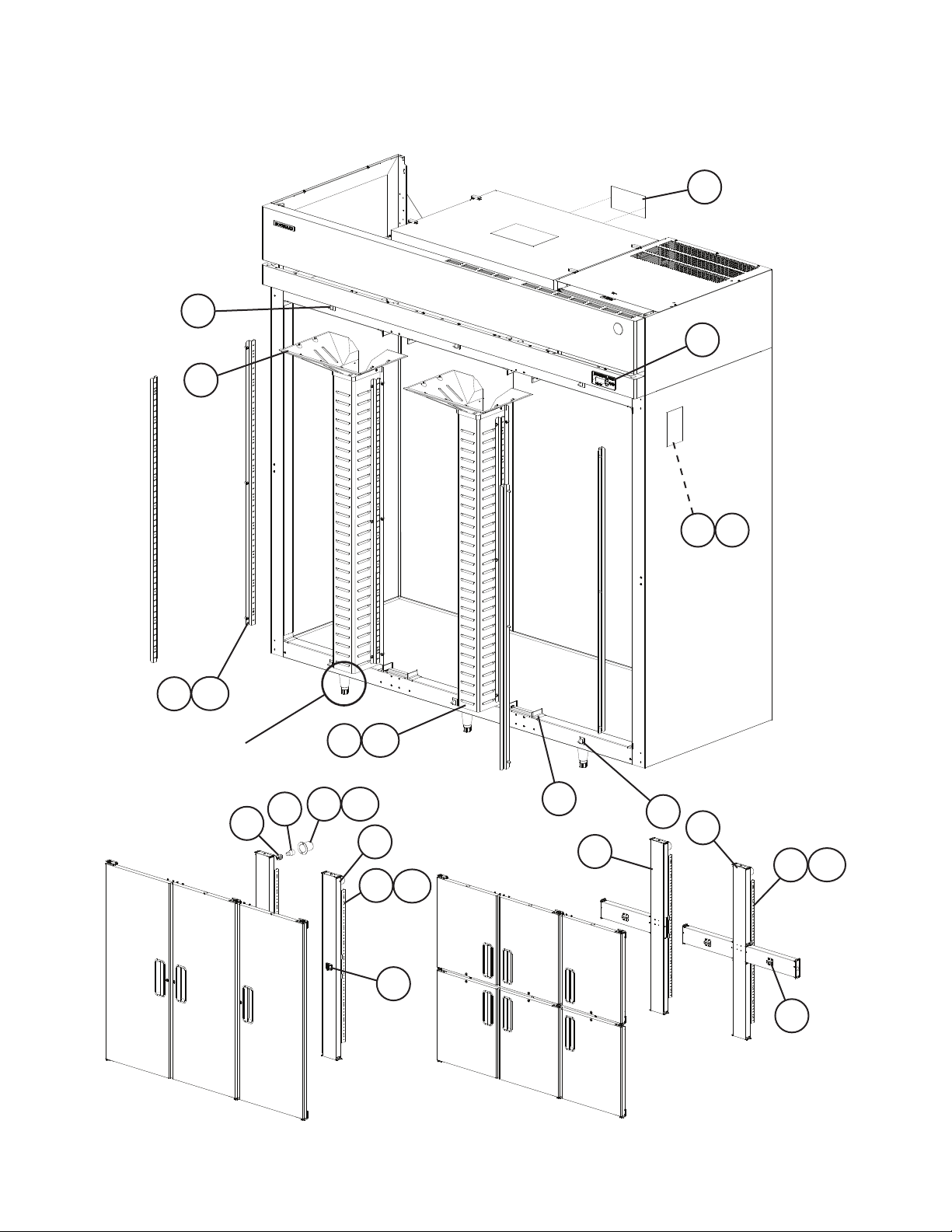
A. Reach-In Assembly RH3-SSE-FS, RH3-SSE-HS
U-5 to A-5
6
17
4
3
1 2
16a
16
For Legs, see
section "G"
Full Doors
10
15a
15
12a
12
11
7
13a
13
14
For Doors, see sections "E" and "F"
5
Half Doors
Half Doors
9
6
8
13a
13
14
4
Page 5
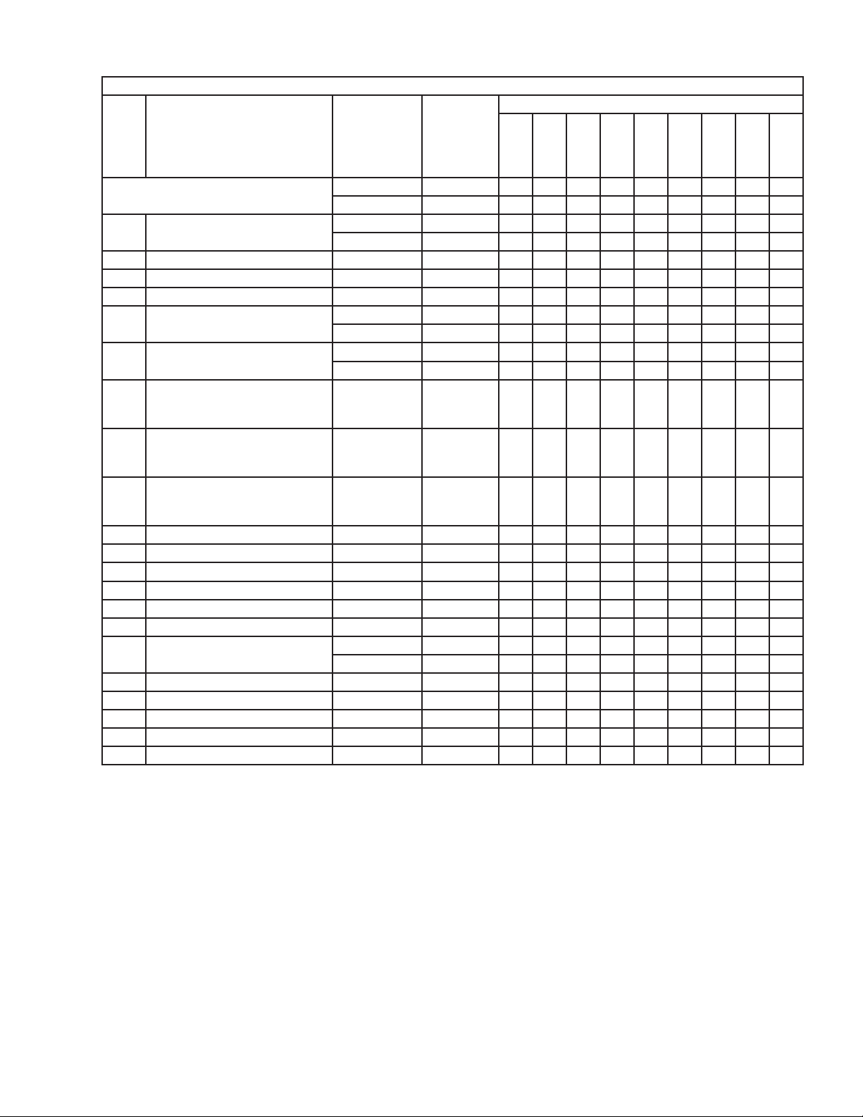
Title: A. Reach-In Assembly Models: RH3-SSE-FS, RH3-SSE-HS
U-5
to
Index
No. Description
Reach-In Assembly
Order Assembly Parts Individually
1 Nameplate RH3-SSE-FS 2A4847-05 1 1
2 Nameplate Cover 4A3727-01 1 1
3 Display Label 3A5788-01 1 1
4 Caution Label 4A1931-01 1 1
5 Corner Cover RH3-SSE-FS 3A1751-01 12 12
6 Door Switch RH3-SSE-FS 3A1826-01 3 3
7 Vertical Mullion (includes half
the quantity of items 10 through
14)
8 Cross Mullion (includes half the
quantity of items 10 through 13,
and 4 of item 14)
9 Tee Mullion (includes half the
quantity of items 10 through 13,
and 2 of item 14)
10 Lamp Holder 4A2862-01 2 2
11 Light Bulb 4A2420-01 2 2
12 Light Shield 4A0465-01 2 2
12a Cheese Head Screw 7C52-0512 4 4
13 Mullion Pilaster 2A3246-01 4 4
13a Truss Head Screw 5×10, SS 7C32-0510 12 12
14 Strike Plate RH3-SSE-FS 4A4587-01 4 4
15 Air Distributor (bottom) 1A0985-01 2 2
15a Truss Head Screw 5×10, SS 7C32-0510 12 12
16 Pilaster 3A0145-01 8 8
16a Truss Head Screw 5×10, SS 7C32-0510 24 24
17 Air Distributor (top) 1A0152-02 2 2
Material or
Model Number Part Number
RH3-SSE-FS 1A1788A01 1 1
RH3-SSE-HS 1A1789A01 1 1
RH3-SSE-HS 2A4847-06 1 1
RH3-SSE-HS 3A1751-01 24 24
RH3-SSE-HS 3A1826-01 6 6
RH3-SSE-FS 2A4211G01 2 2
RH3-SSE-HS 2A4254G01 1 1
RH3-SSE-HS 2A4569G01 1 1
RH3-SSE-HS 4A4587-01 6 6
V-5
(F)
Required Number
V-5
(G)
to
A-5
5
Page 6
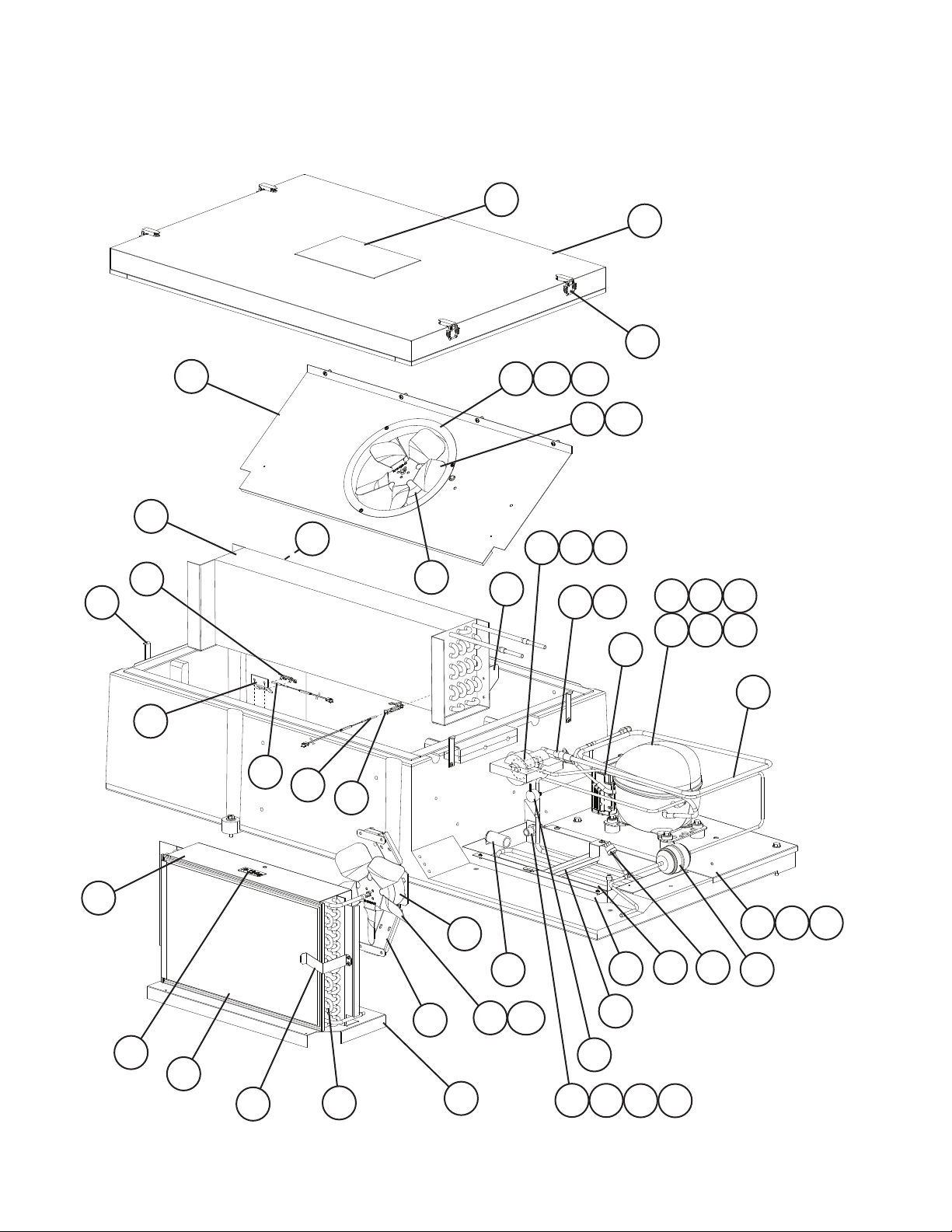
B. Refrigeration Circuit
RH3-SSE-FS, RH3-SSE-HS
U-5 to A-5
17
6
7
35
39
41
9
4
8
10
43
42
37
40
36
36a
12
36b
38
13
14
15 16
38a
3
2
2c
2a 2b
2e
2d
11
20
18
26
22
21
23
24
19
6
25
5
25a
29
34
30
28
27
31
33
32
45
1
44
1a 1b
Page 7

Title: B. Refrigeration Circuit Model: RH3-SSE-FS, RH3-SSE-HS
V-5
U-5
(J)
to
to
Index
No. Description
Refrigeration Circuit
Order Assembly Parts Individually
1 Compressor Base 2A2333G01 1 1 1
1a Flat Washer 7W21-0800 2 2 2
1b Hex Head Bolt 8×70 7B01-0870 2 2 2
2 Compressor 4A4622-01 1 1 1
2a Grommet 434403-01 4 4 4
2b Spacer 434404-01 4 4 4
2c Hex Head Bolt 8×45 7B01-0845 4 4 4
2d Split Lock Washer 7L21-0800 4 4 4
2e Flat Washer 7W21-0800 4 4 4
3 Electronic Unit 4A4673-01 1 1 1
4 Catch Latch 4A3987-01 4 4 4
5 Evaporator Drain Pipe 3A0143-01 1 1 1
6 Evaporator Case Cover
(includes Item 7)
7 Draw Latch 4A3988-01 4 4 4
8 Cabinet Thermistor Mount
Bracket
9 Cabinet Thermistor Clip
Bracket
10 Cabinet Thermistor 4A1429-02 1 1 1
11 Heat Exchanger 2A4828G01 1 1 1
12 Expansion Valve 4A4599-01 1 1 1
13 Expansion Valve Cover A 3A0372-01 1 1 -
Expansion Valve Cover 4A4646-01 1
14 Expansion Valve Cover B 3A0372-02 1 1 15 Expansion Valve Bulb Holder 3A0107-01 1 1 1
16 Clamp 443461-01 1 1 1
17 Wiring Label 2A4829-012 1 -
18 R134a Label 444463-01 1 1 1
19 Condenser Base 2A1168-01 1 1 1
20 Condenser Shroud 2A1715-01 1 1 1
21 Condenser 2A1166-01 1 1 1
22 Filter Retainer 4A2138-01 1 1 1
23 Condenser Fan Bracket 3A1564-01 1 1 1
24 Condenser Fan Motor 4A4621-01 1 1 1
25 Condenser Fan Blade 3A0608-01 1 1 1
25a Hex Nut 4A1345-01 1 1 1
26 Air Filter 3A0277-03 1 1 1
27 Evaporator Drain Pan 2A0200-02 1 1 1
28 Condensate Coil Strap 3A0413-03 1 1 1
29 Overow Drain Fitting w/Nut 4A2182-01 1 1 1
30 Rubber Gasket 413854-03 1 1 1
31 Silicone Hose L=350 7730I3812 1 1 1
Material or
Model Number Part Number
1A1781A01 1 1 1
2A4474A01 1 1 1
433964-01 1 1 1
433920-01 1 1 1
2A4829-013 1 1
V-5
(H)
A-5
(E)
Required Number
A-5
(F)
7
Page 8

Title: B. Refrigeration Circuit Model: RH3-SSE-FS, RH3-SSE-HS
V-5
U-5
(J)
to
to
Index
No. Description
32 Elbow 4A0711-01 1 1 1
33 Condensate Coil 2A1856-01 1 1 1
34 Clogged Filter Thermostat 4A0484-01 1 1 1
35 Evaporator Shroud 1A1782-01 1 1 1
36 Evaporator Fan Orice 4A0412-01 1 1 1
36a Lock Washer 4A0459-01 3 3 3
36b T2 Screw 4×8, SS 7P32-0408 3 3 3
37 Evaporator Fan Motor 4A4620-01 1 1 1
38 Evaporator Fan Blade 3A0436-01 1 1 1
38a Hex Nut 4A1345-01 1 1 1
39 Evaporator 2A1159-01 1 1 1
40 Right Evaporator Shroud
Bracket
41 Left Evaporator Shroud
Bracket
42 Thermistor Clip 320418-01 1 1 1
43 Defrost Thermistor 4A1428-02 1 1 1
44 Drier 4A0924-01 1 1 1
45 High-Pressure Switch 4A2516-01 1 1 1
Material or
Model Number Part Number
4A4793-01 1 1 1
4A4793-02 1 1 1
V-5
(H)
A-5
(E)
Required Number
A-5
(F)
8
Page 9

C. Control Box Assembly
RH3-SSE-FS, RH3-SSE-HS
U-5 to A-5
9
10 11
12
7
6
5
4
13
3
Compressor Relay
Title: C. Control Box Assembly Model: RH3-SSE-FS, RH3-SSE-HS
U-5
to
Index
No. Description
Control Box Assembly
Order Assembly Parts Individually
1 Control Board 2A2862-23 1 -
2 Board Support 4A0336-03 6 6 6
3 Ground Screw 433304-02 1 1 1
4 Terminal Block 4A2619-01 1 1 1
5 Control Transformer 3A1759-01 1 1 1
6 Switch Bracket 2A1032-02 1 1 1
7 Power Switch 4A0424-01 1 1 1
8 Perimeter Heater Switch 4A0418-01 1 1 1
9 Control Box Cover 2A1031-01 1 1 1
10 Power Switch Label 4A2196-01 1 1 1
11 Perimeter Heater Switch Label 4A1039-01 1 1 1
12 Display Information Label 3A1413-01 1 1 1
13 Power Cord 4A0520-01 1 1 1
14 Compressor/Perimeter Heater
Relay
Material or
Model Number Part Number
2A4830A01 1 1 1
2A2862-24 1 1
4A4329-01 2 2 1
V-5
(E)
V-5
(F-H)
8
1 2
Perimeter Heater Relay
V-5 (H) and earlier
14
Required Number
V-5
(J)
to
A-5
9
Page 10

D. Upper Panel & Control Panel Assembies
RH3-SSE-FS, RH3-SSE-HS
U-5 to A-5
9
8
6
7
14
2
1
3a 3b
10
11
4
10
11
16
3
13
12
2
5
9
8
7
15
17
22
18
10
3a
18a
3b
21
19
1
3
20
19a
Page 11

Title: D. Upper Panel & Control Panel Assembies Model: RH3-SSE-FS, RH3-SSE-HS
U-5
Index
No. Description
Upper Panel Assembly
Order Assembly Parts Individually
1 Side Top Frame 2A1803-01 2
2 Hinge Bracket 4A2306-01 2
3 Side Top Panel 2A1800-01 2
3a Taper Collar 4H0171-01 4
3b Countersunk Screw 5×20, SS 7C42-0520 4
4 Front Panel 1A0624-03 1
5 Right Front Panel Hinge 4A2154-01 1
6 Left Front Panel Hinge 4A2153-01 1
7 Hinge Channel 4A2170-01 2
8 Clevis Pin 8907-0102 2
9 Hinge Spacer 4A2473-01 2
10 Flat Washer 4A0655-03 2
11 Cotter Pin 8907-0103 2
12 Top Cover 2A1118-02 1
13 Penguin Label 456246-02 1
14 Emblem 4A0560-01 1
15 Rear Cover 2A1117-01 1
16 Frame Gusset 4A3856-01 1
Control Panel Assembly
Order Assembly Parts Individually
17 Control Panel 1A0836-01 1
18 Display Board Mount 3A0823-01 1
18a Palnut 4A1398-01 6
19 Display Board 2A0883-01 1
19a Nylon Screw 4A1397-01 4
20 Ribbon Cable 4A1106-02 1
21 Board Cover 3A1060-01 1
22 Control Panel Cover 3A1066-01 1
Material or
Model Number Part Number
2A4564A01 1
3A5211A01 1
to
A-5
Required Number
11
Page 12

E. Door-Right Hinged
Full Solid: RH3-SSE-FS
V-5, A-5
16
15
13
4
9
7
20a
20
6
5
3
3a
8
17
10
11
12
14
17
21
18
19
19a
2
12
2a
1a
1
Page 13

Title: E. Door-Right Hinged Model: Full Solid: RH3-SSE-FS
Index
No. Description
Door-Right Hinged; Full Solid
Order Assembly Parts Individually
1 Door Hinge Bracket (LR) 3A1626-01 1 1
1a Countersunk Screw 5×20, SS 7C42-0520 3 3
2 Female Hinge Bottom Plate (R) 4A0441-01 1 1
2a Stop Plate Screw 4A0483-01 1 1
3 Door Hinge Bracket (UR) 3A1580-01 1 1
3a Countersunk Screw 5×20, SS 7C42-0520 3 1
4 Hinge Lock Washer 4A0553-01 1 3
5 Hinge Pivot Pin 4A2179-01 1 1
6 Hinge Stop Pin (top) 4A2180-01 1 1
7 Hinge Bushing Cover 4A0445-01 1 1
8 Hinge Tension Screw 4A0446-01 1 1
9 Truss Head Screw (ll screws) 5×10, SS 7C32-0510 6 6
10 Door Lock Tumbler (includes
key 4A0460-01)
11 Door Lock Washer 4A0670-01 1 1
12 Door Lock Stop Washer 4A0458-01 1 1
13 Door Lock Cam 4A0228-01 1 1
14 Door Lock Lock Washer 4A0459-01 1 1
15 Door Lock Screw 4A0461-01 1 1
16 Door Assembly
(includes items 17 through 21)
17 Foam Pad 4A2257-01 2 2
18 Hinge Bottom Bushing (R) 4A0439-01 1 1
19 Male Hinge Bottom Plate (R) 4A0440-01 1 1
19a Countersunk Screw 5×20, SS 7C42-0520 2 2
20 Hinge Spring Cartridge (R) 4A0438-01 1 1
20a Countersunk Screw 5×20, SS 7C42-0520 2 2
21 Door Gasket 3A0273-01 1 -
Material or
Model Number Part Number
2A3941A01 2 2A6544A01 2
4A0462-01 1 1
2A3940G01 1 2A6545G01 1
2A5192-07 1
V-5
(A-F)
Required Number
V-5
(G)
to
A-5
13
Page 14

E. Door-Right Hinged
Half Solid: RH3-SSE-HS
U-5, A-5
12
19
13
18
18
16
15
14
17
3
11
25
25
24a
24
6
2
11
4
2
1
1a
10
22a
22
21
23
6a
5
5a
8
20
24
22
24a
25
6
22a
14
10
23
25
6a
9
7
21
9a
Page 15

Title: E. Door-Right Hinged Model: Half Solid: RH3-SSE-HS
Index
No. Description
Door-Right Hinged; Half Solid
Order Assembly Parts Individually
1 Door Hinge Bracket (UR) 3A1580-01 1 1
1a Countersunk Screw 5×20, SS 7C42-0520 3 3
2 Hinge Lock Washer 4A0553-01 2 2
3 Hinge Pivot Pin (top) 4A2179-01 1 1
4 Hinge Stop Pin (top) 4A2180-01 1 1
5 Door Hinge Bracket (UL) 3A1581-01 1 1
5a Countersunk Screw 5×20, SS 7C42-0520 3 3
6 Female Hinge Bottom Plate (R) 4A0441-01 2 2
6a Stop Plate Screw 4A0483-01 2 2
7 Hinge Pivot Pin (center) 4A1735-01 1 1
8 Hinge Stop Pin (center) 4A1734-01 1 1
9 Door Hinge Bracket (LR) 3A1626-01 1 1
9a Countersunk Screw 5×20, SS 7C42-0520 3 3
10 Hinge Tension Screw 4A0446-01 2 2
11 Hinge Bushing Cover 4A0445-01 2 2
12 Door Lock Tumbler (includes
key 4A0460-01)
13 Door Lock Stop Washer 4A0458-01 2 2
14 Door Lock Cam 4A0228-01 2 2
15 Door Lock Washer 4A0670-01 2 2
16 Door Lock Screw 4A0461-01 2 2
17 Door Lock Lock Washer 4A0459-01 2 2
18 Truss Head Screw (ll screws) 5×10, SS 7C32-0510 9 9
19 Door (UR) (includes 1/2 the
quantity of items 21 through 25)
20 Door (LR) (includes 1/2 the
quantity of items 21 through 25)
21 Door Gasket 3A0273-02 2 -
22 Hinge Spring Cartridge (R) 4A0438-01 2 2
22a Countersunk Screw 5×20, SS 7C42-0520 4 4
23 Hinge Bottom Bushing (R) 4A0439-01 2 2
24 Male Hinge Bottom Plate (R) 4A0440-01 2 2
24a Countersunk Screw 5×20, SS 7C42-0520 4 4
25 Foam Pad 4A2257-01 4 4
Material or
Model Number Part Number
2A3936A01 2 2A6548A01 2
4A0462-01 2 2
2A3934G01 1 2A6549G01 1
2A3935G01 1 2A6550G01 1
2A5192-08 2
U-5 A-5
Required Number
15
Page 16

F. Door-Left Hinged
Full Solid: RH3-SSE-FS
V-5, A-5
20
20a
17
5
7
6
4
3
3a
8
9
21
19
16
18
19a
11
13
15
10
14
12
17
10
2a
1
2
1a
16
Page 17

Title: F. Door-Left Hinged Model: Full Solid: RH3-SSE-FS
Index
No. Description
Door-Left Hinged; Full Solid
Order Assembly Parts Individually
1 Door Hinge Bracket (LL) 3A1627-01 1 1
1a Countersunk Screw 5×20, SS 7C42-0520 3 3
2 Female Hinge Bottom Plate (L) 4A0441-02 1 1
2a Stop Plate Screw 4A0483-01 1 1
3 Door Hinge Bracket (UL) 3A1581-01 1 1
3a Countersunk Screw 5×20, SS 7C42-0520 3 3
4 Hinge Lock Washer 4A0553-01 1 1
5 Hinge Pivot Pin (top) 4A2179-01 1 1
6 Hinge Stop Pin (top) 4A2180-01 1 1
7 Hinge Bushing Cover 4A0445-01 1 1
8 Hinge Tension Screw 4A0446-01 1 1
9 Truss Head Screw (ll screws) 5×10, SS 7C32-0510 6 6
10 Door Lock Tumbler (includes
key 4A0460-01)
11 Door Lock Washer 4A0670-01 1 1
12 Door Lock Stop Washer 4A0458-01 1 1
13 Door Lock Cam 4A0228-01 1 1
14 Door Lock Lock Washer 4A0459-01 1 1
15 Door Lock Screw 4A0461-01 1 1
16 Door Assembly
(includes items 17 through 21)
17 Foam Pad 4A2257-01 2 2
18 Hinge Bottom Bushing (L) 4A0439-02 1 1
19 Male Hinge Bottom Plate (L) 4A0440-02 1 1
19a Countersunk Screw 5×20, SS 7C42-0520 2 2
20 Hinge Spring Cartridge (L) 4A0438-02 1 1
20a Countersunk Screw 5×20, SS 7C42-0520 2 2
21 Door Gasket 3A0273-01 1 -
Material or
Model Number Part Number
2A3943A01 1 2A6546A01 1
4A0462-01 1 1
2A3942G01 1 2A6547G01 1
2A5192-07 1
V-5
(A-F)
Required Number
V-5
(G)
to
A-5
17
Page 18

F. Door-Left Hinged
Half Solid: RH3-SSE-HS
U-5, A-5
3
11
22a
22
25
10
4
2
1
1a
18
24
22
19
2
24a
7
22a
20
21
23
6
11
25
25
12
5
10
6a
8
5a
15
13
18
14
16
17
21
24
23
24a
25
6a
6
9
9a
18
18
Page 19

Title: F. Door-Left Hinged Model: Half Solid: RH3-SSE-HS
Index
No. Description
Door-Left Hinged; Half Solid
Order Assembly Parts Individually
1 Door Hinge Bracket (UL) 3A1581-01 1 1
1a Countersunk Screw 5×20, SS 7C42-0520 3 3
2 Hinge Lock Washer 4A0553-01 2 2
3 Hinge Pivot Pin (top) 4A2179-01 1 1
4 Hinge Stop Pin (top) 4A2180-01 1 1
5 Door Hinge Bracket (UR) 3A1580-01 1 1
5a Countersunk Screw 5×20, SS 7C42-0520 3 3
6 Female Hinge Bottom Plate
(L)
6a Stop Plate Screw 4A0483-01 2 2
7 Hinge Pivot Pin (center) 4A1735-01 1 1
8 Hinge Stop Pin (center) 4A1734-01 1 1
9 Door Hinge Bracket (LL) 3A1627-01 1 1
9a Countersunk Screw 5×20, SS 7C42-0520 3 3
10 Hinge Tension Screw 4A0446-01 2 2
11 Hinge Bushing Cover 4A0445-01 2 2
12 Door Lock Tumbler (includes
key 4A0460-01)
13 Door Lock Stop Washer 4A0458-01 2 2
14 Door Lock Cam 4A0228-01 2 2
15 Door Lock Washer 4A0670-01 2 2
16 Door Lock Screw 4A0461-01 2 2
17 Door Lock Lock Washer 4A0459-01 2 2
18 Truss Head Screw (ll screws) 5×10, SS 7C32-0510 9 9
19 Door (UL) (includes half the
quantity of items 21 through
25)
20 Door (LL) (includes half the
quantity of items 21 through
25)
21 Door Gasket 3A0273-02 2 -
22 Hinge Spring Cartridge (L) 4A0438-02 2 2
22a Countersunk Screw 5×20, SS 7C42-0520 4 4
23 Hinge Bottom Bushing (L) 4A0439-02 2 2
24 Male Hinge Bottom Plate (L) 4A0440-02 2 2
24a Countersunk Screw 5×20, SS 7C42-0520 4 4
25 Foam Pad 4A2257-01 4 4
Material or
Model Number Part Number
2A3939A01 1 2A6551A01 1
4A0441-02 2 2
4A0462-01 2 2
2A3937G01 1 2A6552G01 1
2A3938G01 1 2A6553G01 1
2A5192-08 2
U-5 A-5
Required Number
19
Page 20

G. Accessories & Packaging
RH3-SSE-FS, RH3-SSE-HS
U-5 to A-5
Title: G. Accessories & Packaging Model: RH3-SSE-FS, RH3-SSE-HS
Index
No. Description
1 Instruction Manual 91A3ME10C 1
2 Shelf 3 Pack (each kit contains
1/3 the quantity of item 3)
3 Shelf Clip 428957-01 36
4 Center Shelf 3 Pack HS-3510 3A1417A03 2
5 Leg (2 Pack) HS-3511 4A0930-02 1
6 Leg (4 Pack) HS-3512 4A0930-01 1
Packaging RH3-SSE-FS 2A5037A01 1
Material or
Model Number Part Number
HS-3508 3A1416A03 3
RH3-SSE-HS 2A5038A01 1
Required Number
U-5
to
A-5
20
 Loading...