

Page 1

Hoshizaki
Hoshizaki America, Inc.
Professional Series
Refrigerated Kitchen Equipment
Models
RH1-SSE-FG
“A Superior Degree
of Reliability”
www.hoshizaki.com
RH1-SSE-HG
RH1-SSE-FS
RH1-SSE-HS
PARTS LIST
Number: 71301
Issued: 1-22-2010
Page 2

CONTENTS
Auxiliary Codes ...................................................................................................................... 3
Note About Ordering Parts .................................................................................................... 3
Material Abbreviations ........................................................................................................... 4
A. Reach-In Assembly ............................................................................................................ 5
RH1-SSE-FG ..................................................................................................................... 5
RH1-SSE-HG..................................................................................................................... 7
RH1-SSE-FS ..................................................................................................................... 9
RH1-SSE-HS ....................................................................................................................11
B. Refrigeration Circuit ......................................................................................................... 13
C. Control Box Assembly ..................................................................................................... 18
D. Control Panel Group ........................................................................................................ 20
E. Light Group ...................................................................................................................... 21
F. Upper Panel Group .......................................................................................................... 22
G. Door-Right ....................................................................................................................... 24
Full Glass: RH1-SSE-FG ................................................................................................. 24
Half Glass: RH1-SSE-HG ................................................................................................ 26
Full Solid: RH1-SSE-FS ................................................................................................... 28
Half Solid: RH1-SSE-HS .................................................................................................. 30
H. Accessories & Packaging ................................................................................................ 32
2
Page 3

Auxiliary Codes
RH1-SSE-FG V-5 January 2010
RH1-SSE-HG U-5 January 2009
V-5 January 2010
RH1-SSE-FS U-5 November 2009
V-5 January 2010
RH1-SSE-HS U-5 December 2009
V-5 January 2010
Auxiliary Code Breakdown
The auxiliary code is the rst two characters in the serial number. The rst character
indicates the year. Years progress or regress in alphabetical order. The series runs from
"A" through "V" and the letters "I" and "O" are skipped. The second character indicates
signicant part changes within a year. Base is "5" and this number advances for each
change.
Note About Ordering Parts
Most assemblies cannot be ordered as complete units; parts in the assemblies generally
must be ordered separately.
3
Page 4

Material Abbreviations
ALUMINUM
AL = Aluminum
COPPER
CU = Copper
PLASTIC
ABS = Acrylonitrile -butadiene - styrene
AC = Polyacetal
EVA = Ethylene vinyl acetate
PA = Polyamide = Nylon
PC = Polycarbonate
PE = Polyethylene
PES = Polyester
PETP = Polyethylene terephthalate = Tetlon
PP = Polypropylene
PS = Polystyrene
PTFE = Polytetrauoroethylene = Teon
PUR = Polyurethane
PVC = Polyvinyl chloride
RUBBER
VN = Vinyl Nitrile
EPDM = EP rubber
NBR = Nitrile butadiene rubber
NR = Natural rubber
NP = Neoprene
SI.R = Silicone rubber
SY.R = Synthetic rubber
EPH = Epichlorohydrin
STEEL
GS = Galvanized steel
SS = Stainless steel
PS = Plated steel
PAS = Primed steel
4
Page 5
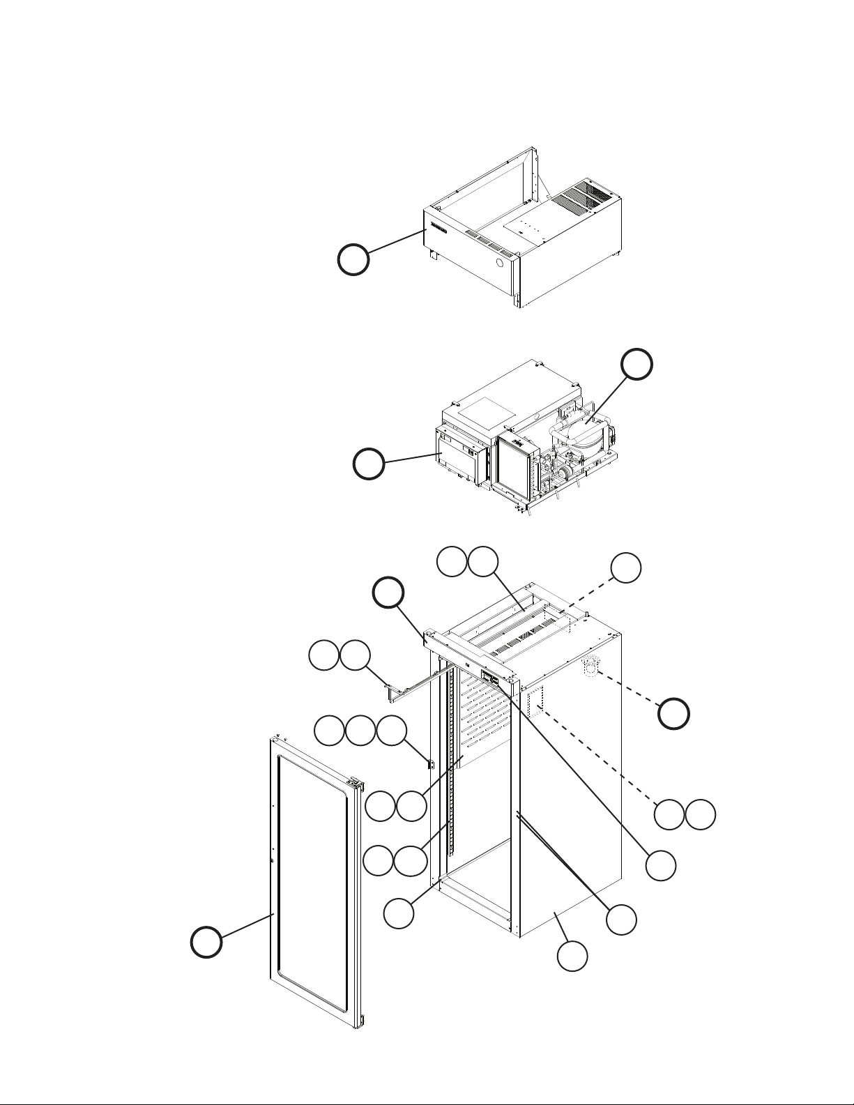
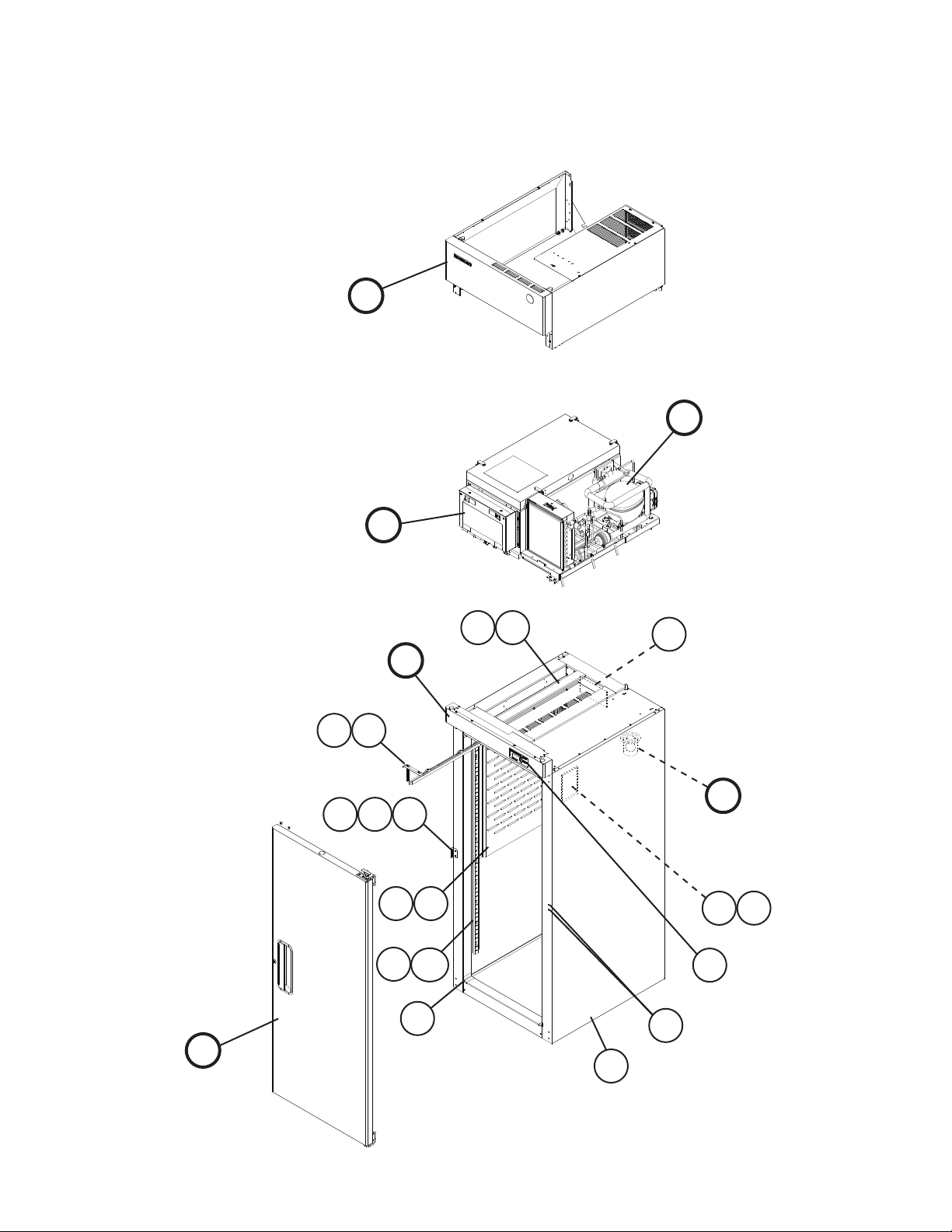
A. Reach-In Assembly
RH1-SSE-FG
V-5
F
B
C
G
6a
6
7
D
5a
5
E
4a
4
3
12 13
14a
14
2
10
11
1
9
8
5
Page 6
Title: A. Reach-In Assembly Model: RH1-SSE-FG
Index
No. Description
B Refrigeration Circuit (For
mounting hardware, see
section "B" items 1 through 3)
C Control Box Assembly (For
mounting hardware, see
section "J" item 1)
D Control Panel Group (For
mounting hardware, see
section "D" item 1)
E Light Group (For mounting
hardware, see section "E" item
1a)
F Upper Panel Group (For
mounting hardware, see
section "F" item 1)
G Door-Right (For mounting
hardware, see section "G"
item 1)
1 Body 1A1388G01 1
2 Corner Cover 3A1751-01 4
3 Strike Group (includes items 4
and 4a)
4 Strike Plate 4A4587-01 1
4a T2 Screw 4×8, SS 7P32-0408 2
5 Upper Air Distributor Group
(includes item 5a)
5a T2 Screw 4×8, SS 7P32-0408 7
6 Air Divider Group (includes
item 6a)
6a T2 Screw 4×8, SS 7P32-0408 4
7 Caution Label 4A1931-01 1
8 Nameplate 2A4848-01 1
9 Nameplate Cover 4A3727-01 1
10 Display Label 3A5788-01 1
11 T2 Screw (ller) 4×8, SS 7P32-0408 2
12 Interior Group (includes items
13 through 14a)
13 Air Distributor 2A0425-01 1
14 Pilaster 3A0145-01 4
14a Truss Head Screw 5×10, SS 7C32-0510 12
Material or
Model Number Part Number
1A1653A01 1
2A4830A01 1
Glass Door 3A4567A01 1
3A4196A01 1
2A4303A01 1
Full Glass 2A4423A01 1
4A4588A01 1
3A4526A01 1
3A4164A01 1
3A4569A01 1
Required Number
V-5
6
Page 7
A. Reach-In Assembly
RH1-SSE-HG
U-5, V-5
F
B
C
G
7a
7
8
D
6a
6
11
E
9
10
4
13 14
5a
5
3
15a
15
2
12
1
7
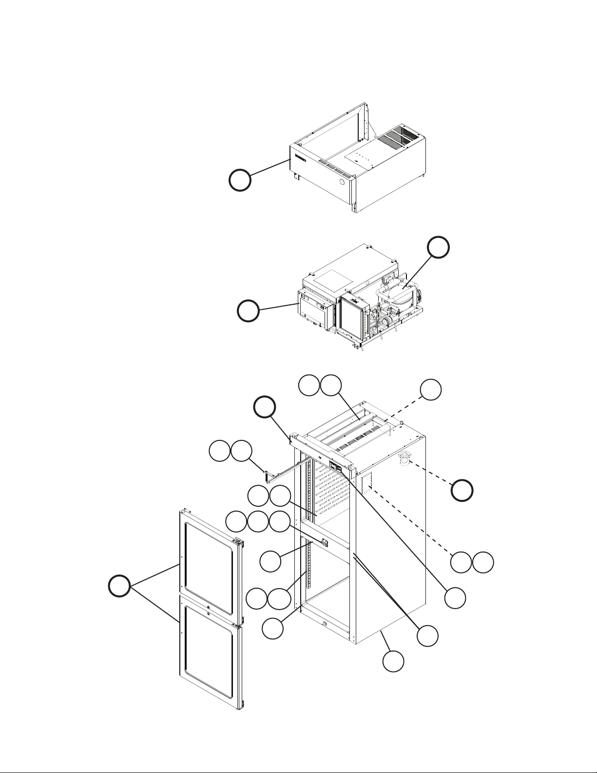
Page 8
Title: A. Reach-In Assembly Model: RH1-SSE-HG
Index
No. Description
B Refrigeration Circuit (For
mounting hardware, see
section "B" items 1 through 3)
C Control Box Assembly (For
mounting hardware, see
section "J" item 1)
D Control Panel Group (For
mounting hardware, see
section "D" item 1)
E Light Group (For mounting
hardware, see section "E" item
1a)
F Upper Panel Group (For
mounting hardware, see
section "F" item 1)
G Door-Right (For mounting
hardware, see section "G"
item 1)
1 Body 1A1461G01 1
2 Corner Cover 3A1751-01 8
3 Horizontal Mullion (includes
item 4)
4 Strike Group (includes items 5
and 5a)
5 Strike Plate 4A4587-01 2
5a T2 Screw 4×8, SS 7P32-0408 4
6 Upper Air Distributor Group
(includes item 6a)
6a T2 Screw 4×8, SS 7P32-0408 7
7 Air Divider Group (includes
item 7a)
7a T2 Screw 4×8, SS 7P32-0408 4
8 Caution Label 4A1931-01 1
9 Nameplate 2A4848-02 1
10 Nameplate Cover 4A3727-01 1
11 Display Label 3A5788-01 1
12 T2 Screw (ller) 4×8, SS 7P32-0408 2
13 Interior Group (includes items
14 through 15a)
14 Air Distributor 2A0425-01 1
15 Pilaster 3A0145-01 4
15a Truss Head Screw 5×10, SS 7C32-0510 12
Material or
Model Number Part Number
1A1653A01 1
2A4830A01 1
Glass Door 3A4567A01 1
3A4196A01 1
2A4303A01 1
Half Glass 2A4418A01 1
2A3917G01 1
4A4588A01 2
3A4526A01 1
3A4164A01 1
3A4569A01 1
Required Number
U-5
V-5
8
Page 9
A. Reach-In Assembly
RH1-SSE-FS
U-5, V-5
F
B
C
G
6a
6
7
D
5a
5
E
4a
4
3
12 13
14a
14
2
10
11
1
9
8
9
Page 10
Title: A. Reach-In Assembly Model: RH1-SSE-FS
Index
No. Description
B Refrigeration Circuit (For
mounting hardware, see
section "B" items 1 through 3)
C Control Box Assembly (For
mounting hardware, see
section "J" item 1)
D Control Panel Group (For
mounting hardware, see
section "D" item 1)
E Light Group (For mounting
hardware, see section "E" item
1a)
F Upper Panel Group (For
mounting hardware, see
section "F" item 1)
G Door-Right (For mounting
hardware, see section "G"
item 1)
1 Body 1A1388G01 1
2 Corner Cover 3A1751-01 4
3 Strike Group (includes items 4
and 4a)
4 Strike Plate 4A4587-01 1
4a T2 Screw 4×8, SS 7P32-0408 2
5 Upper Air Distributor Group
(includes item 5a)
5a T2 Screw 4×8, SS 7P32-0408 7
6 Air Divider Group (includes
item 6a)
6a T2 Screw 4×8, SS 7P32-0408 4
7 Caution Label 4A1931-01 1
8 Nameplate 2A4847-01 1
9 Nameplate Cover 4A3727-01 1
10 Display Label 3A5788-01 1
11 T2 Screw (ller) 4×8, SS 7P32-0408 2
12 Interior Group (includes items
13 through 14a)
13 Air Distributor 2A0425-01 1
14 Pilaster 3A0145-01 4
14a Truss Head Screw 5×10, SS 7C32-0510 12
Material or
Model Number Part Number
1A1653A01 1
2A4830A01 1
Solid Door 3A4501A01 1
3A4196A01 1
2A4303A01 1
Full Solid 2A3941A01 1
4A4588A01 1
3A4526A01 1
3A4164A01 1
3A4569A01 1
Required Number
U-5
V-5
10
Page 11

A. Reach-In Assembly
RH1-SSE-HS
U-5, V-5
F
B
C
G
7a
7
8
D
6a
6
11
E
9
10
4
13 14
5a
5
3
15a
15
2
12
1
11
Page 12

Title: A. Reach-In Assembly Model: RH1-SSE-HS
Index
No. Description
B Refrigeration Circuit (For
mounting hardware, see
section "B" items 1 through 3)
C Control Box Assembly (For
mounting hardware, see
section "J" item 1)
D Control Panel Group (For
mounting hardware, see
section "D" item 1)
E Light Group (For mounting
hardware, see section "E" item
1a)
F Upper Panel Group (For
mounting hardware, see
section "F" item 1)
G Door-Right (For mounting
hardware, see section "G"
item 1)
1 Body 1A1461G01 1
2 Corner Cover 3A1751-01 8
3 Horizontal Mullion (includes
item 4)
4 Strike Group (includes items 5
and 5a)
5 Strike Plate 4A4587-01 2
5a T2 Screw 4×8, SS 7P32-0408 4
6 Upper Air Distributor Group
(includes item 6a)
6a T2 Screw 4×8, SS 7P32-0408 7
7 Air Divider Group (includes
item 7a)
7a T2 Screw 4×8, SS 7P32-0408 4
8 Caution Label 4A1931-01 1
9 Nameplate 2A4847-02 1
10 Nameplate Cover 4A3727-01 1
11 Display Label 3A5788-01 1
12 T2 Screw (ller) 4×8, SS 7P32-0408 2
13 Interior Group (includes items
14 through 15a)
14 Air Distributor 2A0425-01 1
15 Pilaster 3A0145-01 4
15a Truss Head Screw 5×10, SS 7C32-0510 12
Material or
Model Number Part Number
1A1653A01 1
2A4830A01 1
Solid Door 3A4501A01 1
3A4196A01 1
2A4303A01 1
Half Solid 2A3936A01 1
2A3917G01 1
4A4588A01 2
3A4526A01 1
3A4164A01 1
3A4569A01 1
Required Number
U-5
V-5
12
Page 13

B. Refrigeration Circuit
1/2
RH1-SSE-FG, RH1-SSE-HG, RH1-SSE-FS, RH1-SSE-HS
U-5, V-5
39a
39
34 35
46
41
44
36
34a
36a
47
34b
72
18 19 20
66a
66
43
72a
67
37
37a
40
38
45
9
40a
12
11
42
65
42a
21
10
56
61
16 17
13
57
60
64a
64
63
4a
4
4c 4d 4e
4b
13
5
2
68 69 70 71
3
Page 14

B. Refrigeration Circuit
2/2
RH1-SSE-FG, RH1-SSE-HG, RH1-SSE-FS, RH1-SSE-HS
U-5, V-5
58
50
51a
51
25
26
23
22
23a
22a
24
27
30a 30b 30c
30
27a
28
33
62
31
29a 29b
32
6a
6
54
7
53
14
15
8
29
48 49
55
59
52a
52
1 2
14
3
Page 15

Title: B. Refrigeration Circuit Model: RH1-SSE-FG, RH1-SSE-HG, RH1-SSE-FS, RH1-SSE-HS
Required Number
Index
No. Description
1 Hex Head Bolt w/Washer 8×45 437889-01 2
2 Hex Head Bolt 8×70 7B01-0870 3
3 Flat Washer M8 7W21-0800 3
4 Compressor NLV6.1F
4a Hex Head Bolt 8×45 7B01-0845 4
4b Split Lock Washer M8 7L21-0800 4
4c Flat Washer M8 7W21-0800 4
4d Grommet 434403-01 4
4e Spacer 434404-01 4
5 Electronic Unit 105N4212 4A4673-01 1
6 Cabinet Thermistor Bracket 433964-01 1
6a Truss Head Screw 4×16, SS 7C32-0416 2
7 Cabinet Thermistor Bracket 433920-01 1
8 Cabinet Thermistor 4A1429-01 1
9 Compressor-Condenser
Assembly (includes items 10
through 12)
10 Clogged Filter Thermostat 4A0484-01 1
11 Access Valve 457729-01 1
12 Condensate Coil 3A1644-01 1
13 Expansion Valve 4A4597-01 1
14 Expansion Valve Cover A 3A0372-01 1
15 Expansion Valve Cover B 3A0372-02 1
16 Expansion Valve Holder 3A0107-01 1
17 Clamp 443461-01 1
18 Condenser-Drier Assembly
(includes items 19 through 21)
19 Drier 4A0924-01 1
20 Nylon Tie 8911-0300 1
21 Pressure Switch 4A2516-01 1
22 Evaporator Assembly (includes
items 22a through 26)
22a Truss Head Screw 4×12, SS 7C32-0412 2
23 Evaporator Bracket 4A2542-01 2
23a T2 Screw 4×8, SS 7P32-0408 4
24 Evaporator 2A1262-01 1
25 Defrost Thermistor 4A1428-01 1
26 Thermistor Clip 320418-01 1
27 Evaporator Fan Assembly
(includes items 27a through 33)
27a Truss Head Screw 4×12, SS 7C32-0412 4
28 Evaporator Fan Shroud SS 2A0846-01 1
29 Fan Motor Bracket SS 3A2501-01 2
29a Truss Head Screw 5×12, SS 7C32-0512 2
29b Lock Washer 4A0459-01 2
30 Evaporator Fan Motor 4A2563-01 1
30a Truss Head Screw 4×40, SS 7C32-0440 4
30b Split Lock Washer M4, SS 7L22-0400 4
30c Hex Nut M4, SS 7N12-0400 4
Material or
Model Number Part Number
4A4648-01 1
105G5661
2A4840G01 1
3A5090G01 1
2A4839A01 1
2A4369A01 1
U-5
V-5
15
Page 16

Title: B. Refrigeration Circuit Model: RH1-SSE-FG, RH1-SSE-HG, RH1-SSE-FS, RH1-SSE-HS
Required Number
Index
No. Description
31 Wire Tie 4A1223-01 1
32 Evaporator Fan Blade 4A2378-01 1
33 PVC Gasket L=522 4A0414L03 1
34 Condenser Assembly (includes
items 34a through 47)
34a Truss Head Screw 5×25, SS 7C32-0525 2
34b T2 Screw 4×8, SS 7P32-0408 2
35 Condenser 2A0623-01 1
36 Condenser Base GS 2A2724G01 1
36a T2 Screw 4×8, SS 7P32-0408 2
37 Condenser Shroud GS 2A2722-01 1
37a T2 Screw 4×8, SS 7P32-0408 6
38 Condenser Fan Motor
(mounting screws included)
39 Condenser Fan Blade 3A0436-01 1
39a Hex Nut 4A1345-01 1
40 Condenser Fan Bracket GS 3A1564-01 1
40a Truss Head Screw 5×12, SS 7C32-0512 4
41 Air Filter 3A0277-01 1
42 Air Filter Retainer SS 4A0790-01 1
42a T2 Screw 4×8, SS 7P32-0408 2
43 Grommet Strip L=242 4A1341L01 1
44 Grommet Strip L=33 4A1341L01 1
45 Nylon Tie 8911-0200 3
46 Foam Tape L=185 8208-0005 1
47 R134a Label 444463-01 1
48 Process Tube Assembly
(includes item 49)
49 Access Valve 457729-01 1
50 Evaporator Case Cover
(includes items 51 and 51a)
51 Draw-Latch 4A3988-01 4
51a T2 Screw 4×8, SS 7P32-0408 8
52 Catch-Latch GS 4A3987-01 4
52a Truss Head Screw 4×16, SS 7C32-0416 4
53 Evaporator Tubing Seal 4A3089-01 2
54 Insulation Tubing L=200 7762-1030 2
55 Insulation Tubing L=130 7762-3555 1
56 Wire Tie-Twist 4A1223-01 2
57 Locking Hole Plug 4A0586-02 1
58 Wiring Label 2A4829-01 1
59 Heat Exchanger 3A5089G01 1
60 Tube-90 Bend 3A2620-19 1
61 Evaporator Drain Pipe 4A0831-01 1
62 Evaporator Case 1A1412G01 1
63 Compressor Base Assembly
(includes items 64 through 72a)
64 Compressor Base 2A2756G01 1
64a Truss Head Screw 4×16, SS 7C32-0416 1
65 Evaporator Drain Pan 2A2760-01 1
Material or
Model Number Part Number
3A5085A01 1
4A4620-01 1
4A4657G01 1
2A4376G01 1
2A4365A01 1
U-5
V-5
16
Page 17

Title: B. Refrigeration Circuit Model: RH1-SSE-FG, RH1-SSE-HG, RH1-SSE-FS, RH1-SSE-HS
Required Number
Index
No. Description
66 Condensate Coil Strap 3A0232-03 1
66a Truss Head Screw 5×12, SS 7C32-0512 1
67 Condensate Coil Gasket 4A0455-03 1
68 Drain Overow Fitting 4A2182-01 1
69 Rubber Gasket 413854-03 1
70 Silicone Hose L=300mm 7730I3812 1
71 Elbow-Tubing 4A0711-01 1
72 Wire Clamp 4A0809-01 1
72a T2 Screw 4×8, SS 7P32-0408 1
Material or
Model Number Part Number
U-5
V-5
17
Page 18

C. Control Box Assembly
RH1-SSE-FG, RH1-SSE-HG, RH1-SSE-FS, RH1-SSE-HS
U-5, V-5
32
9a
27
35
12
13
22
9
7
8
15
30a
30
21
24
4
31
33
29
29a
16
3
28
20
23
19
26
10
25
10a
18
11
6
5
34
1
14
5a
17
2
Title: C. Control Box Assembly Model: RH1-SSE-FG, RH1-SSE-HG, RH1-SSE-FS, RH1-SSE-HS
Required Number
Index
No. Description
1 Truss Head Screw 4×16, SS 7C32-0416 4
2 Power Supply Cord 4A0520-01 1
3 Wire Clamp 4A0809-02 1
4 Bushing 420470-01 1
5 Defrost Relay 4A4329-01 2
5a T2 Screw 4×8, SS 7P32-0408 4
6 Common Control Box (includes
items 1 and 7 through 35)
7 Control Board 2A2862-23 1
8 Board Support CBLS37-M 4A0336-03 6
9 Control Box Cover 2A1031-01 1
9a T2 Screw 4×8, SS 7P32-0408 2
Material or
Model Number Part Number
2A4831A01 1
U-5
V-5
18
Page 19

Title: C. Control Box Assembly Model: RH1-SSE-FG, RH1-SSE-HG, RH1-SSE-FS, RH1-SSE-HS
Required Number
Index
No. Description
10 Switch Bracket GS 2A1032-02 1
10a T2 Screw 4×8, SS 7P32-0408 2
11 Bushing SB-1093-15 420470-03 1
12 Bushing SB-625-8 420470-01 1
13 Board Connector 5198-10 434003-05 1
14 Board Connector 5198-07 434003-07 1
15 Board Connector 5198-03 434003-09 1
16 Board Connector 5198-03 Red 434003-11 1
17 Plug Housing 9P 412832-02 1
18 Receptacle Housing 9P 3191-09R1 412831-02 1
19 Plug Housing 6P 3191-06-P 412832-03 1
20 Receptacle Housing 6P 412831-03 1
21 Plug Housing 3P 03-12-1036 4A0425-01 1
22 Receptacle Housing 3P 03-12-1035 4A0426-01 1
23 Plug Housing 4P 3191-04-P 412832-05 1
24 Receptacle Housing 4P 3191-04R1 412831-05 1
25 Plug Housing 2P 3191-02P 412832-07 1
26 Receptacle Housing 2P 3191-02R1 412831-07 1
27 Toggle Switch 4A0424-01 1
28 Rocker Switch 4A0418-01 1
29 Transformer 3A1759-01 1
29a Tapping Screw 3×8 431415-01 2
30 Terminal Block ESB2-323-424 4A2619-01 1
30a Tapping Screw 3×8 431415-01 2
31 Power Label 4A2196-01 1
32 Perimeter Heater Switch Label 4A1039-01 1
33 Display Information Label 3A1413-01 1
34 Control Box Base GS 2A1146-01 1
35 Grounding Screw 433304-02 1
Material or
Model Number Part Number
U-5
V-5
19
Page 20

D. Control Panel Group
RH1-SSE-FG, RH1-SSE-HG, RH1-SSE-FS, RH1-SSE-HS
U-5, V-5
8
3a
5a
5
6
9
2
4a
4
8
3
Title: D. Control Panel Group Model: RH1-SSE-FG, RH1-SSE-HG, RH1-SSE-FS, RH1-SSE-HS
Index
No. Description
1 T2 Screw 4×8, SS 7P32-0408 2
2 Control Panel Glass Door 1A0760-04 1
3 Wire Cover GS 2A1033-01 1
3a T2 Screw 4×8, SS 7P32-0408 4
4 Display Board Mount 3A0823-01 1
4a Palnut 4A1398-01 6
5 Display Board 2A0883-01 1
5a Nylon Screw 4A1397-01 4
6 Ribbon Cable L=610 4A1106-01 1
7 Locking Hole Plug 4A0586-02 1
8 Locking Hole Plug 4A0586-03 2
9 Rocker Switch Glass Door 4A0418-01 1
Material or
Model Number Part Number
Solid Door 1A0760-01 1
U-5
V-5
1
Required Number
7
20
Page 21

E. Light Group
RH1-SSE-FG, RH1-SSE-HG, RH1-SSE-FS, RH1-SSE-HS
U-5, V-5
1
2
3a
3
Title: E. Light Group Model: RH1-SSE-FG, RH1-SSE-HG, RH1-SSE-FS, RH1-SSE-HS
Required Number
Index
No. Description
1 Lampholder 4A2862-01 1
2 Light Bulb 4A2420-01 1
3 Light Shield 4A0465-01 1
3a Cheese Head Screw 5×12, SS 7C52-0512 2
Material or
Model Number Part Number
U-5
V-5
21
Page 22

F. Upper Panel Group
RH1-SSE-FG, RH1-SSE-HG, RH1-SSE-FS, RH1-SSE-HS
U-5, V-5
9a
9
2
10a
9b
10
4c
11a
11
4a 4b
7a
7
3
1
4c
3
2
8
5a
1
4a 4b
8a
Required Number
U-5
V-5
4
5d
13
5
12
Title: F. Upper Panel Group Model: RH1-SSE-FG, RH1-SSE-HG, RH1-SSE-FS, RH1-SSE-HS
Index
No. Description
1 Truss Head Screw 5×10, SS 7C32-0510 8
2 Side Top Frame GS 2A1803-01 2
3 Hinge Bracket GS 4A2306-01 2
4 Side Top Panel SS 2A1800-01 2
4a Taper Collar SS 4H0171-01 4
4b Countersunk Screw 5×20, SS 7C42-0520 4
4c T2 Screw 4×8, SS 7P32-0408 4
5 Front Panel SS 1A0624-01 1
5a Clevis Pin 8907-0102 2
5b Hinge Spacer 4A2473-01 2
5c Flat Washer 4A0655-03 2
5d Cotter Pin 8907-0103 2
6 Hinge Channel GS 4A2170-01 2
7 Front Panel Hinge (L) GS 4A2153-01 1
7a Truss Head Screw 5×8, SS 7C32-0508 2
8 Front Panel Hinge (R) GS 4A2154-01 1
8a Truss Head Screw 5×8, SS 7C32-0508 2
9 UL Top Cover GS 3A4504G01 1
9a T2 Screw 4×8, SS 7P32-0408 2
9b Truss Head Screw 5×10, SS 7C32-0510 1
5c
6
Material or
Model Number Part Number
5b
4
22
Page 23

Title: F. Upper Panel Group Model: RH1-SSE-FG, RH1-SSE-HG, RH1-SSE-FS, RH1-SSE-HS
Required Number
Index
No. Description
10 UL Rear Cover GS 2A4261-01 1
10a T2 Screw 4×8, SS 7P32-0408 2
11 Frame Gusset GS 4A3856-01 1
11a T2 Screw 4×8, SS 7P32-0408 4
12 Penguin Label 456246-02 1
13 Emblem 4A0560-01 1
Material or
Model Number Part Number
U-5
V-5
23
Page 24

G. Door-Right
Full Glass: RH1-SSE-FG
V-5
3
5
For handle, see
section "H"
16
10
23
14
11
12
15
13
4
6
19
1
2
7
18a
18
17
22
16
20
21
20a
24
19
9a
9
1
8
Page 25

Title: G. Door-Right Model: Full Glass: RH1-SSE-FG
Index
No. Description
1 Countersunk Screw 5×20, SS 7C42-0520 6
2 Door Hinge Bracket (UR) 3A1580-01 1
3 Hinge Pivot Pin (Top) 4A2179-01 1
4 Hinge Lock Washer 4A0553-01 1
5 Hinge Stop Pin 4A2180-01 1
6 Hinge Bushing Cover 4A0445-01 1
7 Hinge Tension Screw 4A0446-01 1
8 Door Hinge Bracket (LR) 3A1626-01 1
9 Hinge Bottom Plate-Female (R) 4A0441-01 1
9a Stop Plate Screw 4A0483-01 1
10 Door Lock Tumbler (includes
key 4A0460-01)
11 Door Lock Washer SS 4A0670-01 1
12 Door Lock Stop Washer 4A0458-01 1
13 Door Lock Cam 4A0228-01 1
14 Door Lock Lock Washer 4A0459-01 1
15 Door Lock Screw 4A0461-01 1
16 Truss Head Screw (ller) 5×10, SS 7C32-0510 6
17 Door Subassembly-FG_R
(includes items 18 through 23)
18 Hinge Spring Cartridge (R) 4A0438-01 1
18a Countersunk Screw 5×20, SS 7C42-0520 2
19 Foam Pad 4A2257-01 2
20 Hinge Bottom Plate-Male (R) 4A0440-01 1
20a Countersunk Screw 5×20, SS 7C42-0520 2
21 Hinge Bottom Bushing (R) 4A0439-01 1
22 Door Gasket 3A0273-01 1
23 Locking Hole Plug 4A0586-06 1
Material or
Model Number Part Number
4A0462-01 1
Full Glass 2A4424G01 1
Required Number
V-5
25
Page 26

G. Door-Right
Half Glass: RH1-SSE-HG
U-5, V-5
10
3
1
2
6
5
4
For handle, see
section "H"
27
10
16
24
17
25
24a
18
19
23
23
7
22a
22
20
26
9a
9
1
8
4
12
11
For handle, see
section "H"
27
10
14
24
15
25
24a
26
23
7
23
6
22a
22
21
26
9a
9
1
13
Page 27

Title: G. Door-Right Model: Half Glass: RH1-SSE-HG
Index
No. Description
1 Countersunk Screw 5×20, SS 7C42-0520 9
2 Door Hinge Bracket (UR) 3A1580-01 1
3 Hinge Pivot Pin (Top) 4A2179-01 1
4 Hinge Lock Washer 4A0553-01 2
5 Hinge Stop Pin 4A2180-01 1
6 Hinge Bushing Cover 4A0445-01 2
7 Hinge Tension Screw 4A0446-01 2
8 Door Hinge Bracket (UL) 3A1581-01 1
9 Hinge Bottom Plate-Female (R) 4A0441-01 2
9a Stop Plate Screw 4A0483-01 2
10 Truss Head Screw (ller) 5×10, SS 7C32-0510 9
11 Pivot Pin 4A1735-01 1
12 Stop Pin 4A1734-01 1
13 Door Hinge Bracket (LR) 3A1626-01 1
14 Door Lock Tumbler (with key
4A0460-01)
15 Door Lock Washer SS 4A0670-01 2
16 Door Lock Stop Washer 4A0458-01 2
17 Door Lock Cam 4A0228-01 2
18 Door Lock Lock Washer 4A0459-01 2
19 Door Lock Screw 4A0461-01 2
20 Door Subassembly-HG_UR
(includes half the quantity of
items 22 through 27)
21 Door Subassembly-HG_LR
(includes half the quantity of
items 22 through 27)
22 Hinge Spring Cartridge (R) 4A0438-01 2
22a Countersunk Screw 5×20, SS 7C42-0520 4
23 Foam Pad 4A2257-01 4
24 Hinge Bottom Plate-Male (R) 4A0440-01 2
24a Countersunk Screw 5×20, SS 7C42-0520 4
25 Hinge Bottom Bushing (R) 4A0439-01 2
26 Door Gasket 3A0273-02 2
27 Locking Hole Plug 4A0586-06 2
Material or
Model Number Part Number
4A0462-01 2
Half GlassUpper Right
Half GlassLower Right
2A4419G01 1
2A4420G01 1
Required Number
U-5
V-5
27
Page 28

G. Door-Right
Full Solid: RH1-SSE-FS
U-5, V-5
3
5
16
10
14
11
23
12
15
13
4
6
19
1
2
7
18a
18
17
22
16
20
21
20a
28
19
9a
9
1
8
Page 29

Title: G. Door-Right Model: Full Solid: RH1-SSE-FS
Index
No. Description
1 Countersunk Screw 5×20, SS 7C42-0520 6
2 Door Hinge Bracket (UR) 3A1580-01 1
3 Hinge Pivot Pin (Top) 4A2179-01 1
4 Hinge Lock Washer 4A0553-01 1
5 Hinge Stop Pin 4A2180-01 1
6 Hinge Bushing Cover 4A0445-01 1
7 Hinge Tension Screw 4A0446-01 1
8 Door Hinge Bracket (LR) 3A1626-01 1
9 Hinge Bottom Plate-Female (R) 4A0441-01 1
9a Stop Plate Screw 4A0483-01 1
10 Door Lock Tumbler (includes
key 4A0460-01)
11 Door Lock Washer SS 4A0670-01 1
12 Door Lock Stop Washer 4A0458-01 1
13 Door Lock Cam 4A0228-01 1
14 Door Lock Lock Washer 4A0459-01 1
15 Door Lock Screw 4A0461-01 1
16 Truss Head Screw (ller) 5×10, SS 7C32-0510 6
17 Door Subassembly-FS_R
(includes items 18 through 23)
18 Hinge Spring Cartridge (R) 4A0438-01 1
18a Countersunk Screw 5×20, SS 7C42-0520 2
19 Foam Pad 4A2257-01 2
20 Hinge Bottom Plate-Male (R) 4A0440-01 1
20a Countersunk Screw 5×20, SS 7C42-0520 2
21 Hinge Bottom Bushing (R) 4A0439-01 1
22 Door Gasket 3A0273-01 1
23 Locking Hole Plug 4A0586-06 1
Material or
Model Number Part Number
4A0462-01 1
Full Solid 2A3940G01 1
Required Number
U-5
V-5
29
Page 30

G. Door-Right
Half Solid: RH1-SSE-HS
U-5, V-5
10
27
3
1
2
6
23
5
4
7
22a
22
20
26
10
14
16
24
17
25
24a
18
15
19
23
23
9a
9
1
8
4
12
11
6
7
22a
22
21
26
10
27
24
25
24a
30
23
9a
9
1
13
Page 31

Title: G. Door-Right Model: Half Solid: RH1-SSE-HS
Index
No. Description
1 Countersunk Screw 5×20, SS 7C42-0520 9
2 Door Hinge Bracket (UR) 3A1580-01 1
3 Hinge Pivot Pin (Top) 4A2179-01 1
4 Hinge Lock Washer 4A0553-01 2
5 Hinge Stop Pin 4A2180-01 1
6 Hinge Bushing Cover 4A0445-01 2
7 Hinge Tension Screw 4A0446-01 2
8 Door Hinge Bracket (UL) 3A1581-01 1
9 Hinge Bottom Plate-Female (R) 4A0441-01 2
9a Stop Plate Screw 4A0483-01 2
10 Truss Head Screw (ller) 5×10, SS 7C32-0510 9
11 Pivot Pin 4A1735-01 1
12 Stop Pin 4A1734-01 1
13 Door Hinge Bracket (LR) 3A1626-01 1
14 Door Lock Tumbler (with key
4A0460-01)
15 Door Lock Washer SS 4A0670-01 2
16 Door Lock Stop Washer 4A0458-01 2
17 Door Lock Cam 4A0228-01 2
18 Door Lock Lock Washer 4A0459-01 2
19 Door Lock Screw 4A0461-01 2
20 Door Subassembly-HS_UR
(includes half the quantity of
items 22 through 27)
21 Door Subassembly-HS_LR
(includes half the quantity of
items 22 through 27)
22 Hinge Spring Cartridge (R) 4A0438-01 2
22a Countersunk Screw 5×20, SS 7C42-0520 4
23 Foam Pad 4A2257-01 4
24 Hinge Bottom Plate-Male (R) 4A0440-01 2
24a Countersunk Screw 5×20, SS 7C42-0520 4
25 Hinge Bottom Bushing (R) 4A0439-01 2
26 Door Gasket 3A0273-02 2
27 Locking Hole Plug 4A0586-06 2
Material or
Model Number Part Number
4A0462-01 2
Half SolidUpper Right
Half SolidLower Right
2A3934G01 1
2A3935G01 1
Required Number
U-5
V-5
31
Page 32

H. Accessories & Packaging
RH1-SSE-FG, RH1-SSE-HG, RH1-SSE-FS, RH1-SSE-HS
U-5, V-5
2
Shelf Kit
Includes 3 shelves
and 12 clips
3
5
4
6a
8a
8
6b
7
6
Title: H. Accessories & Packaging Model: RH1-SSE-FG, RH1-SSE-HG, RH1-SSE-FS, RH1-SSE-HS
Required Number
Index
No. Description
1 Instruction Manual 91A3ME10A 1
2 Shelf Kit (3 Pack) (includes
items 3 and 4)
3 Shelf 3A1387-01 3
4 Shelf Clip 428957-01 12
5 Leg Kit (4 pack) HS-3512 4A0930-01 1
6 Handle RH1-SSE-FG 115365-01 1
6a Screw-Bolt RH1-SSE-FG 449879-08 2
6b Cap-Handle RH1-SSE-FG 360643-01 2
7 Overow Pan 4A3419G01 1
8 Overow Pan Bracket (A) 4A0878-01 1
8a T2 Screw 4×8, SS 7P32-0408 2
9 Overow Pan Bracket (B) 4A0879-01 1
9a T2 Screw 4×8, SS 7P32-0408 2
Material or
Model Number Part Number
HS-3508 3A1416A03 1
RH1-SSE-HG 2
RH1-SSE-HG 4
RH1-SSE-HG 4
U-5
V-5
9a
9
- Packaging RH1-SSE-FG 2A4857A01
RH1-SSE-HG 2A4858A01
RH1-SSE-FS 2A4855A01
RH1-SSE-HS 2A4856A01
32
 Loading...