

Page 1

Hoshizaki America, Inc.
Hoshizaki
Commercial Refrigerators & Freezers
Models
®
TempGuard & SafeTemp
®
“A Superior Degree
of Reliability”
www.hoshizaki.com
INSTRUCTION MANUAL
Issued: 2-12-2008
Revised: 5-22-2008
Page 2

IMPORTANT
Only qualied service technicians should attempt to install, service, or maintain
this unit. No installation, service, or maintenance should be undertaken until
the technician has thoroughly read this Instruction Manual. Likewise, the
owner/manager should not proceed to operate the unit until the installer has
instructed them on its proper operation. Failure to install, operate, and maintain
the equipment in accordance with this manual may adversely affect safety,
performance, and warranty coverage.
Hoshizaki provides this manual primarily to assist qualied service technicians in the
installation, maintenance, and service of the unit.
Should the reader have any questions or concerns which have not been satisfactorily
addressed, please call, write, or send an e-mail message to the Hoshizaki Technical
Support Department for assistance.
HOSHIZAKI AMERICA, INC.
618 Highway 74 South
Peachtree City, GA 3069
Attn: Hoshizaki Technical Support Department
Phone: 1-800-33-1940 Technical Service
(770) 487-331
Fax: 1-800-843-1056
(770) 487-3360
E-mail: techsupport@hoshizaki.com
Web Site: www.hoshizaki.com
NOTE: To expedite assistance, all correspondence/communication MUST include the
following information:
• Model Number
• Serial Number
• Complete and detailed explanation of the problem.
Page 3

IMPORTANT
This manual should be read carefully before the unit is installed and operated.
Only qualied service technicians should install, service, and maintain the unit.
Read the warnings contained in this booklet carefully as they give important
information regarding safety. Please retain this booklet for any further reference
that may be necessary.
CONTENTS
I. Installation Instructions ....................................................................................................... 5
A. Location ........................................................................................................................ 5
B. Checks Before Installation ............................................................................................ 5
C. Setup ............................................................................................................................ 6
1. General .................................................................................................................... 6
. Overow Pan ........................................................................................................... 7
3. Electrically Heated Condensate Pan ....................................................................... 7
4. Food Cart Ramp (Roll In and Roll Thru Units) ........................................................ 8
D. Electrical Connection .................................................................................................... 8
E. How to Open the Front Panel ....................................................................................... 9
F. Door Reversal (except heated glass doors) .................................................................. 9
G. Final Checklist ............................................................................................................ 10
II. Operating Instructions ..................................................................................................... 11
A. Operation ................................................................................................................... 11
B. Startup ........................................................................................................................ 1
C. Cabinet Temperature .................................................................................................. 1
1. TempGuard Models ............................................................................................... 1
a) Temperature Display .......................................................................................... 1
b) Adjusting the Temperature Setpoint ................................................................... 13
c) Changing the Temperature Display Scale (°F or °C) .......................................... 13
. SafeTemp Models ................................................................................................. 13
a) Temperature Display .......................................................................................... 13
b) Temperature Setpoint ......................................................................................... 14
c) Changing the Temperature Display Scale (°F or °C) .......................................... 14
D. Defrost ........................................................................................................................ 14
1. TempGuard Models ............................................................................................... 14
a) For Refrigerators ................................................................................................ 14
b) For Freezers ....................................................................................................... 15
. SafeTemp Models ................................................................................................. 15
a) For Refrigerators ................................................................................................ 15
b) For Freezers ....................................................................................................... 15
E. Food Storage .............................................................................................................. 16
F. Perimeter Frame Heater ............................................................................................. 16
G. Safety Devices ........................................................................................................... 16
1. High Pressure Switch ............................................................................................ 16
. Compressor Short Cycle Timer ............................................................................. 16
a) TempGuard Models ............................................................................................ 16
b) SafeTemp Models .............................................................................................. 16
3. Compressor Protector ........................................................................................... 17
4. Defrost Protection .................................................................................................. 17
3
Page 4

H. Shutdown and Long Storage ...................................................................................... 17
III. Cleaning and Maintenance Instructions ......................................................................... 18
A. Cleaning ...................................................................................................................... 18
1. Exterior .................................................................................................................. 18
. Interior ................................................................................................................... 18
3. Door Gaskets ........................................................................................................ 18
4. Shelves .................................................................................................................. 18
5. Glass Door ............................................................................................................ 18
B. Maintenance ............................................................................................................... 19
1. Air Filter(s) ............................................................................................................. 19
. Condenser(s) ......................................................................................................... 19
3. Power Supply Connection ..................................................................................... 19
IV. Troubleshooting ............................................................................................................. 0
A. Alarm Code Appears in Display .................................................................................. 0
1. TempGuard Models ............................................................................................... 0
. SafeTemp Models ................................................................................................. 1
B. Poor Cooling Performance .........................................................................................
C. Condensation .............................................................................................................
4
Page 5

I. Installation Instructions
IMPORTANT
Install in accordance with all applicable national, state, and local regulations.
A. Location
CAUTION
This unit is not intended for outdoor use. Normal operating ambient
temperature should be within +45°F to +100°F (+7°C to +38°C). Operation of
the unit, for extended periods, outside of this normal temperature range may
affect unit performance.
For best operating results:
• The unit should be on a at, level, and solid foundation.
• The unit should not be located in a corrosive environment.
• The unit should not be near ovens, grills, or other high heat producing equipment.
• The unit should be a minimum of 4 inches (11 cm) from side walls. More clearance may
be necessary depending on the door combination of the unit.
• A minimum of 10 inches (5 cm) overhead clearance should be provided for proper
ventilation.
• Position unit for convenient usage of front and rear doors.
B. Checks Before Installation
IMPORTANT
Refer to the nameplate for electrical specications. The nameplate is located
on the right side wall of the cabinet interior. For more electrical connection
details, see "I.D. Electrical Connection." We reserve the right to make
specication and design changes without prior notice.
1) Remove the shipping carton, tape, and packing material from the unit prior to
installation (on Roll In and Roll Thru units, leave the internal packaging in place until
the unit is in the nal location). Inspect the equipment for any damage which may have
occurred during shipment. Concealed damage claims must be led with the carrier.
) Remove all accessory containers before discarding the packing materials. Dispose of
all packing materials in a proper and environmentally responsible manner.
3) To remove the unit from the skid:
(a) Move as close to the nal location as possible.
(b) Remove the 5/8 in. bolts that secure the cabinet to the skid, then remove the
cabinet from the skid.
(c) Block the cabinet securely at a height of 8 in. (0 cm) off the oor. Do not lay the
unit down. (Not required for Roll In or Roll Thru units).
5
Page 6

(d) Attach the adjustable legs or the casters provided to the bottom of the cabinet. (Not
required for Roll In or Roll Thru units).
4. For Roll In and Roll Thru units only, remove the internal packaging. Be careful not to
damage the unit when removing the internal packaging.
C. Setup
1. General
1) If the unit is supplied with an overow pan or electrically heated condensate pan, install
as outlined in "I.C.. Overow Pan" or "I.C.3. Electrically Heated Condensate Pan."
After the pan is installed or if the unit does not use a pan, continue to step .
) Visually check that the refrigerant lines do not rub or touch other lines or surfaces and
that the fan blades turn freely.
3) Check that the compressor is snug on all mounting pads.
4) Position the unit in the selected location.
• For units with legs, level in both the front-to-back and side-to-side directions. Turn the
bottom portion of the legs to lower or raise them.
• For units with casters, no adjustment is necessary.
• For Roll In or Roll Thru units, seal the perimeter of the unit with NSF-approved,
food-grade silicone and then see "I.C.4. Food Cart Ramp."
5) Install the shelves (if applicable) using the shelf support clips provided in the accessory
pack. Indexing holes are provided on the pilasters in evenly spaced intervals to assist
you in positioning the support clips at the same height. Two and three section units
may be equipped with center shelves which should be installed after the main shelves
are in place. The center shelf kit contains additional clip(s) which support the center
shelf when the main shelves on one side of the cabinet are not aligned with the main
shelves of the other side of the cabinet.* See Fig. 1.
WARNING
*Without this additional support, under adverse loading conditions, the shelf
assembly could tip.
6) On units without pre-installed door handle(s), install the door handle(s) as illustrated.
See Fig. .
Front View
Center Shelf
Top View
Handle
Main Shelf
Fig. 1
Clip
Main Shelf
6
Cap
Bolt
Fig. 2
Page 7

2. Overow Pan
(if applicable)
Units are supplied with an energy efcient automatic condensate water evaporation
system. The overow pan is supplied for the unlikely event that water cannot evaporate
at a high enough rate. If water is found in the overow pan, call your Hoshizaki Certied
Service Representative for assistance. To install the overow pan, follow the directions
below.
Cabinet
1) Attach the overow pan's brackets by
engaging the tab on the bracket through
the hole in the bottom of the unit and
securing with the four mounting screws
provided. See Fig. 3.
) Slide the plastic pan into place under the
vinyl hose on the back of the cabinet.
Overow Bracket
Tab
Mounting Screws
Overow Pan
Fig. 3
3. Electrically Heated Condensate Pan
(if applicable)
The electrically heated condensate pan is used to evaporate condensate water from the
unit. To install the electrically heated condensate pan, follow the directions below.
WARNING
Verify that power to the unit is disconnected before installing pan.
1) Remove the panel that covers the recess
in the back of the unit. See Fig. 4.
) Route the wire found in the recess in the
back of the unit through the wire cover
and install the wire cover to the unit.
3) Plug the cord (wire) routed in step into
the female plug of the heated pan.
4) Replace the panel to cover the recess in
the back of the unit.
Cover Panel
Heated Pan
Mounting
Plate
Cabinet
Wire
Wire Cover
5) Clip the heated pan onto the mounting
plate and attach to the panel that covers
the recess in the back of the unit using
the 4 screws provided.
6) Install the plug cover to the rear of the
unit.
Plug
Plug Cover
Fig. 4
7
Page 8
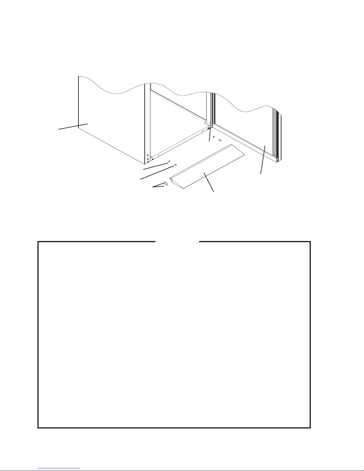
4. Food Cart Ramp (Roll In and Roll Thru Units)
1) Attach the taper collars and countersunk screws to the body. See Fig. 5.
) Attach the ramp ller to the food cart ramp, on the side opposite the door hinge.
3) Hook the food cart ramp over the taper collars.
Body
Door Hinge
Taper Collar
Countersunk Screw
Ramp Filler and Screw
Food Cart Ramp
Door
D. Electrical Connection
1. Make sure the power switch is off before making electrical connections to
reduce the risk of electric shock.
. Failure to use a proper breaker or fuse can result in a tripped breaker, blown
fuse, or damage to existing wiring. This could lead to heat generation or re.
3. The connections must be made to an independent power supply or
receptacle in accordance with national, state, and local electrical code
requirements and this Instruction Manual. Branching off the power cord,
using an extension cord, or sharing a single power supply with other
appliances may result in electric shock, heat generation, or re.
4. This unit should be disassembled or repaired only by a qualied service
technician to reduce the risk of electric shock or re.
5. Do not make any alterations to the unit. Alterations could result in water leak,
electric shock, or re.
6. Do not damage the power cord. It should not be altered, jerked, bundled,
weighed down, pinched, or tangled. Such actions could result in electric
shock or re. To unplug the unit, be sure to pull the attachment plug and do
not jerk the power cord.
Fig. 5
WARNING
7. To reduce the risk of electric shock, do not touch the attachment plug or
power switch with damp hands.
8
Page 9
• Electrical connections must be installed in accordance with applicable national, state,
and local regulations.
• The maximum allowable voltage variation is ±10 percent of the nameplate rating.
• Cord-connected units should only be plugged into a 115 volt ±10%, 60 Hz circuit with a
national and local electrical code approved, grounded wall receptacle. An independent
circuit with its own circuit breaker (HACR type) or fuse (LP-CC type) should be
provided. Refer to the nameplate for the proper electrical specications.
• Hardwired units should only be wired into the proper conduit, with its own circuit
breaker (HACR type) or fuse (LP-CC type). Electrical connection must be made in
accordance with the instructions on the "WARNING" tag, provided with the pig tail
leads in the junction box. Miswiring results in severe damage to the unit. Refer to the
nameplate for the proper electrical specications.
• Usually an electrical permit and services of a licensed electrician are required.
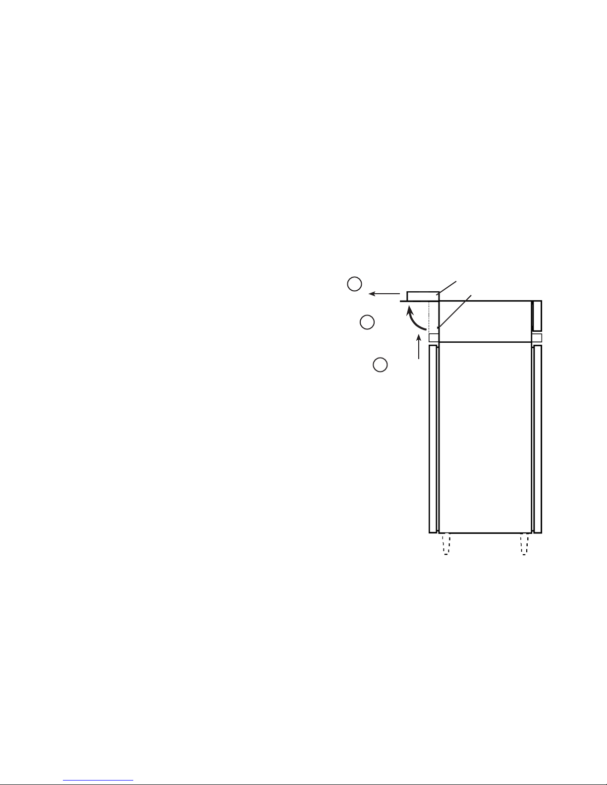
E. How to Open the Front Panel
1) Push the front panel up approximately
1/ inch (1.3 cm) until it is disengaged
from the locking collars and stops. See
Fig. 6.
) Rotate the panel up and away from the
face of the unit until it stops once more.
3) Pull the front panel forward until the hinge
assembly is in the locked position.
3
Pull Forward
Rotate
1
Fig. 6
Front Panel
Locking Collar
Push Up
F. Door Reversal (except heated glass doors)
This unit is provided with a cabinet design which, after being delivered to the installation
location, permits changing the door swing of doors from left to right or right to left. To
change the door swing, special accessories are required. If installed improperly, the
doors will not close and seal correctly. Contact your local Hoshizaki distributor, or the
Hoshizaki Technical Support Department at 1-800-33-1940, if door reversal is desired.
9
Page 10

G. Final Checklist
1) Is the unit level? On a Roll In or Roll Thru unit, is the perimeter of the unit sealed with
NSF-approved, food-grade silicone?
) Is the unit in a site where the ambient temperature is within +45°F to +100°F (+7°C to
+38°C) all year around?
3) Is there at least 10 inches (5 cm) overhead clearance for proper ventilation?
4) Have the shipping carton, tape, and packing material been removed from the unit?
5) Has the unit been checked for shipping damage?
6) Has the power supply been checked or tested against the nameplate rating? Has a
proper ground been installed to the unit?
7) If the unit is supplied with an overow pan or electrically heated condensate pan, has it
been properly installed?
8) Have the refrigerant lines been checked to make sure they do not rub or touch other
lines or surfaces? Have the fan blades been checked to make sure that they turn
freely? Are the compressor hold-down bolts snug?
9) Have the shelves (if applicable) been properly installed?
10) Have the door handles (if applicable) been properly installed?
11) If the unit utilizes a food cart ramp, has it been properly installed?
1) Has the end user been given the instruction manual, and instructed on how to operate
the unit and the importance of the recommended periodic maintenance?
13) Has the end user been given the name and telephone number of a Hoshizaki Certied
Service Representative?
14) Has the warranty card been lled out and forwarded to the factory for warranty
registration?
10
Page 11

II. Operating Instructions
A. Operation
1. Do not leave the doors open.
. Open and close the doors with care. Doors opened too quickly or forcefully
may cause injury or damage to the unit or surrounding equipment.
3. To prevent deformation or cracks, do not spray insecticide onto the plastic
parts or let them come into contact with oil.
4. To avoid damage to the gasket, use only the door handle (do not grab the
top of the door directly) when opening and closing.
1. To reduce the risk of electric shock, do not touch the attachment plug or
power switch with damp hands.
. Do not hang on or push down on the doors. The doors might be damaged,
fall off, or the unit could tip over, causing injury.
IMPORTANT
WARNING
3. Do not store any volatile or ammable substances, such as benzine,
ether, alcohol, adhesives, or LPG in the unit. They are potential sources of
explosion or re.
4. Do not throw anything onto the shelves or load any single shelf with more
than 10 lb (54.5 kg) of product. They might fall off and cause injury.
5. Do not store food or food containers near the air outlet. They might freeze up
and crack or break causing a risk of injury or contamination of other food.
6. Do not use combustible spray or place volatile and ammable substances
near the unit. They might catch re.
7. Do not place anything on top of the unit. Foreign objects or moisture could
enter the unit and result in electric shock or re. Blockage of airow could
also negatively affect performance and damage the equipment.
11
Page 12

B. Startup
CAUTION
All parts are factory adjusted. Improper adjustments may result in failure or loss
of product.
Supply power to the unit. Open the front panel for access to the power switch—located
on the front of the control box—and move the switch to the "ON" position. Allow the unit
to pull down prior to loading it with food products.
IMPORTANT
• TempGuard Refrigerators and Freezers: At startup, there is a 1/ minute
delay before the compressor starts.
Note: On Dual Temp units, there is a delay of approximately 10 seconds
between one compressor start (i.e. freezer) and the next compressor
start (i.e. refrigerator).
• SafeTemp Refrigerators: At startup, there is a minute delay before the
compressor starts.
• SafeTemp Freezers: At startup, a defrost is initiated.
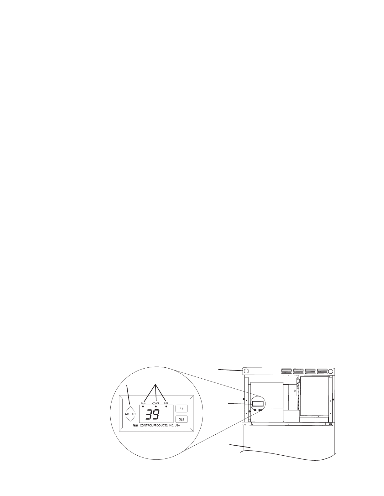
C. Cabinet Temperature
1. TempGuard Models
a) Temperature Display
• The cabinet temperature is displayed on the control panel. See Fig. 7. The display
default is °F, but it can be changed to read °C. To change, see "II.C.1.c) Changing the
Temperature Display Scale (°F or °C)".
• The cabinet temperature is updated every 0 seconds.
Front Panel
Control
Fig. 7
Panel
1
Door
Arrow
Page 13
b) Adjusting the Temperature Setpoint
The temperature setpoint is the value for the average cabinet temperature. The
temperature differential for the compressor to turn on and off is ±3°F of the setpoint. For
example, setpoint = 36°F, compressor on at 39°F, compressor off at 33°F. If necessary,
adjust the setpoint temperature as follows:
1) Press and hold the up/down arrows simultaneously for 3 seconds. The current
temperature setpoint will be displayed.
) To change the setpoint, press the up/down arrows until the desired value is displayed.
For refrigerators, the cabinet temperature is adjustable between 36°F and 50°F (.°C
and 10°C). The factory default is 36°F (.°C). For freezers, the cabinet temperature
is adjustable between -10°F and 5°F (-3.3°C and -3.9°C). The factory default is -3°F
(-19.4°C).
3) Press "ENTER" to set the value and view the next setting. If no change in the value
is desired, press "ENTER", and the next setting will be displayed. At the end of the
sequence, press "ENTER", and the unit will return to normal display mode.
Important Note: For the change to take effect, you must cycle through the menu until
you return to the normal display.
c) Changing the Temperature Display Scale (°F or °C)
To change the display scale, follow the steps below.
1) Press and hold the up/down arrows simultaneously for 3 seconds. Press "ENTER" until
the F or C temperature display scale is displayed.
) To change the temperature display, press the up/down arrows until the desired scale is
displayed. The factory default is °F.
3) Press "ENTER" to set the value and return to normal display mode.
Important Note: For the change to take effect, you must return to the normal display.
2. SafeTemp Models
a) Temperature Display
• The cabinet temperature is displayed on the control panel. See Fig. 8. The cabinet
temperature is displayed in °F only.
• The cabinet temperature is updated every seconds.
• When the fan or compressor is energized or defrost is initiated, the corresponding
indicator light turns on.
Front Panel
Control
Panel
Fig. 8
Arrow
Indicator
Lights
Door
13
Page 14

b) Temperature Setpoint
The temperature setpoint is the temperature at which the compressor comes on. For
refrigerators, the temperature differential for the compressor to turn off is -5°F. For
freezers, the temperature differential for the compressor to turn off is -6°F. If necessary,
adjust the setpoint temperature as follows:
1) Press "SET." The display reads: SP1
) Press "SET." The display reads: Current Setpoint
3) Use the up/down arrows to change the setpoint. For refrigerators, the cabinet
temperature is adjustable between 37°F and 55°F. The factory default is 39°F. For
freezers, the cabinet temperature is adjustable between -10°F and 8°F. The factory
default is -1°F for 1-section freezers and 0°F for -section freezers.
4) Press "SET" to save. If no button is pressed in 15 seconds, the display will return to
normal, and the setpoint will remain unchanged.
c) Changing the Temperature Display Scale (°F or °C)
The cabinet temperature on SafeTemp models can be displayed in °F only.
D. Defrost
1. TempGuard Models
a) For Refrigerators
This unit uses an off-cycle defrost. When a sensor in the evaporator coil reaches the
initiation setpoint, the unit enters defrost. When the sensor reaches the termination
setpoint, the unit ends defrost. After defrost, there is a 5 minute delay before the
compressor will start.
Units with a control board of revision level R3 or later (board revision level can be seen
on display at power up) also feature an adjustable time-initiated defrost along with the
normal temperature-initiated defrost.
The time-initiated defrost is factory set for normal conditions. Before changing this
setting, contact the Hoshizaki Technical Support Department at 1-800-33-1940 for
recommendations. If necessary, adjust the time-initiated defrost frequency as follows:
1) Press and hold the up/down arrows simultaneously for 3 seconds. Press "ENTER" until
the dF frequency is displayed.
) To change the time-initiated defrost frequency, press the up/down arrows until the
desired value is displayed. The defrost frequency is adjustable between 0 and 1
defrosts per 4 hours. The factory default is 0.
3) Press "ENTER" to set the value and view the next setting. If no change in the value is
desired, press "ENTER" and the unit will return to normal display mode.
Important Note: For the change to take effect, you must cycle through the menu until
you return to the normal display.
Note: The change in the defrost setting will take effect after the next defrost based
on the previous setting. To make this change in interval timing take effect
immediately, turn the unit off and back on. The next time-initiated defrost will take
effect "x" hours after power is resupplied. For example, if the setting is dF 6, x=4
and the next defrost will take place 4 hours from the time that power is supplied.
14
Page 15

b) For Freezers
This unit is preset at the factory to defrost 6 times per day for general conditions. Note
that the defrost is a heated defrost, and therefore will have a tendency to raise the
cabinet temperature. Cabinet temperature is not displayed during defrost; "dEF" is
displayed in its place. When a sensor in the evaporator coil reaches the termination
setpoint, the unit ends defrost. After defrost, there is a 5 minute delay before the
compressor will start.
Before changing the defrost frequency setting, contact the Hoshizaki Technical Support
Department at 1-800-33-1940 for recommendations. If necessary, adjust the defrost
frequency as follows:
1) Press and hold the up/down arrows simultaneously for 3 seconds. Press "ENTER" until
the dF frequency is displayed.
) To change the time-initiated defrost frequency, press the up/down arrows until the
desired value is displayed. The defrost frequency is adjustable between 1 and 8
defrosts per 4 hours. The factory default is 6.
3) To save the value, press "ENTER" repeatedly until you have cycled through the menu
and the unit returns to the normal display mode. If you do not cycle through the menu
and no button is pressed in 15 seconds, the display will return to normal and the
defrost frequency will remain unchanged.
Note: The change in the defrost setting will take effect after the next defrost based
on the previous setting. To make this change in interval timing take effect
immediately, turn the unit off and back on. The next defrost will take effect "x"
hours after power is resupplied. For example, if set df 6, x=4, the next defrost will
take place 4 hours from the time that power is applied.
2. SafeTemp Models
a) For Refrigerators
This unit uses an off-cycle defrost. A sensor in the evaporator coil determines the need
for a defrost. When the sensor reaches the initiation setpoint, the unit enters defrost.
When the unit reaches the termination setpoint, the unit ends defrost. After defrost, there
is a 5 minute delay before the compressor will start. The off-cycle defrost requires no
programming; it automatically initiates and terminates.
b) For Freezers
This unit is preset at the factory to defrost 6 times per day for general conditions. Note
that the defrost is a heated defrost, and therefore will have a tendency to raise the
cabinet temperature. Cabinet temperature is not displayed during defrost; "dEF" is
displayed in its place. When a sensor in the evaporator coil reaches the termination
setpoint, the unit ends defrost. After defrost, there is a 5 minute delay before the
compressor will start. When the compressor starts, the display changes to "rEC". Once
the cabinet thermistor drops to 15°F above the setpoint, the display reverts back to
cabinet temperature.
15
Page 16

E. Food Storage
• This unit is designed only for temporary storage of food. Employ sanitary methods. Use
for any other purposes (for example, storage of chemicals or medical supplies such as
vaccine and serum) could cause deterioration of stored items.
• Do not block the air inlet and outlet or cooling performance may be reduced.
• Do not pack the cabinet tightly with food. Allow some space between items/containers to
ensure good air ow. Also allow space between food product and interior surfaces.
• Do not put warm or hot foods in the unit. Let them cool rst, or they will raise the cabinet
temperature and could deteriorate other foods in the cabinet or overload the unit.
• All foods should be wrapped in plastic lm or packed in a container. Otherwise foods
may dry up, pass their smells onto other foods, cause frost to develop, result in poor unit
performance, or increase the likelihood of cross-contamination. Certain dressings and
food ingredients, if not stored in containers, may accelerate corrosion of the evaporator,
resulting in failure.
• On Roll In or Roll Thru units, before rolling the food cart into the cabinet, ensure that all
food containers are arranged evenly and not protruding beyond the cart.
• On Roll In or Roll Thru units, place the food trays evenly from the bottom rst on the food
cart to reduce the risk of tipping the food cart.
F. Perimeter Frame Heater
This unit is equipped with a perimeter frame heater. This prevents the formation of
condensate on the front frame and rear frame (Pass Thru and Roll Thru) of the unit
under high humidity conditions. If operating the unit under conditions where condensate
will not form, these heaters may be turned off using the switch on the control box.
G. Safety Devices
1. High Pressure Switch
• If pressure on the high-side of the unit exceeds Hoshizaki specications, a high
pressure switch activates and interrupts power to the compressor relay. This power
interruption shuts down the compressor.
• The high pressure switch resets automatically.
2. Compressor Short Cycle Timer
a) TempGuard Models
There is a 1/ minute minimum off-time and on-time for the compressor.
• Any time the compressor is started, it will keep running for a minimum of 1/ minutes.
• Any time the compressor is turned off, it will stay off for a minimum of 1/ minutes.
Note: Time may vary with high pressure switch activation.
b) SafeTemp Models
There is a minute minimum off-time and on-time for the compressor.
• Any time the compressor is started, it will keep running for a minimum of minutes.
• Any time the compressor is turned off, it will stay off for a minimum of minutes.
Note: Time may vary with pressure switch activation.
16
Page 17

3. Compressor Protector
• If a combined temperature/amperage value is above the limit specied by the
compressor manufacturer, a protector operates independently to turn off the
compressor. The compressor restarts when this protector has reset.
• The compressor protector resets automatically.
• If the condenser fan is operating and the compressor is off, it is likely that the protector
has operated.
4. Defrost Protection
For freezers, primary defrost termination is controlled by the defrost thermistor. However,
two additional safeties are also present:
• Defrost Time Termination - 1 hour maximum
• Defrost Backup Temperature Termination - Measured by a separate device that is
in-line with the heater(s) and independent of the control board.
H. Shutdown and Long Storage
WARNING
1. When preparing the unit for long storage, prevent the doors from closing to
reduce the risk of children getting trapped.
. To reduce the risk of electric shock, do not touch the attachment plug or
power switch with damp hands.
3. To unplug the unit, be sure to pull the attachment plug and do not jerk the
power cord. It could be damaged and cause re or electric shock.
4. When shutting down the unit for more than one week, turn off the power
switch and unplug the unit.
5. Do not plug in/unplug the unit to start/stop operation. Make sure the power
switch is off before plugging in or unplugging the unit to reduce the risk of
electric shock.
1) Before shutting down the unit, move the stored food into another refrigerator or freezer.
) Open the front panel and move the power switch to the "OFF" position. The unit will
shut down.
3) Unplug the unit.
4) Close the front panel.
IMPORTANT
When preparing the unit for long storage, clean the cabinet interior, door
gaskets, and shelves. See "III.A. Cleaning and Maintenance Instructions" for
details.
17
Page 18

III. Cleaning and Maintenance Instructions
A. Cleaning
WARNING
1. Do not splash water directly onto the unit. This might cause short circuit,
electric shock, corrosion, or failure.
. When cleaning or inspecting the unit, turn off the power switch and unplug
or disconnect power to the unit to reduce the risk of electric shock by
unexpected entrance of water into the unit, or injury by any moving parts.
3. Before using a sanitizer such as inert soap and sodium hypochlorite
(chlorine bleach), thoroughly read the manufacturer’s instructions on its
proper usage.
IMPORTANT
1. To prevent damage to the painted or plastic surfaces, do not use the
following: thinner, benzine, alcohol, petroleum, soap powder, polishing
powder, alkaline cleaner, acid, scouring pad and especially those strong
cleaners for use on a ventilating fan or a cooking range. Also, to prevent
corrosion, do not use sodium hypochlorite (chlorine bleach) on the stainless
steel surfaces.
. Use a clean cloth for cleaning.
3. Before cleaning the cabinet interior, move the stored foods into another
clean refrigerator or freezer.
1. Exterior
Wipe the exterior occasionally with a clean, soft cloth. Use a damp cloth containing a
neutral cleaner to wipe off oil or dirt buildup.
2. Interior
Spills should be wiped up promptly to avoid unpleasant odors. The cabinet interior
should be cleaned periodically with a mild soap or detergent and warm water.
3. Door Gaskets
Door gaskets should be cleaned regularly with mild soap and warm water to remove dirt
and grease.
4. Shelves
Remove and clean regularly.
5. Glass Door
Wipe the exterior occasionally with a clean, soft cloth. Use a damp cloth containing a
neutral cleaner to wipe off oil or dirt build up.
18
Page 19

B. Maintenance
1. Air Filter(s)
Plastic mesh air lter(s) remove dirt and dust from the air, and keep the condenser from
getting clogged. As the lter(s) get clogged, the unit's performance will be reduced.
Check the lter(s) at least twice a month. When clogged, use warm water and a neutral
cleaner to wash the lter(s).
2. Condenser(s)
Check the condenser(s) (located behind the air lter(s)) once a year and use a brush or
vacuum cleaner to clean the condenser(s) as required.
3. Power Supply Connection
If the plug or power cord is damaged, contact a Hoshizaki Certied Service
Representative immediately and ask for repairs.
All other maintenance or service on this unit should be performed in accordance with the
Hoshizaki Service Manual by a qualied service technician.
19
Page 20

IV. Troubleshooting
WARNING
1. This unit should be disassembled or repaired only by a qualied service
technician to reduce the risk of injury, electric shock, or re.
. Do not make any alterations to the unit. This could cause water leak, electric
shock, or re.
3. To reduce the risk of electric shock, do not touch the attachment plug or
power switch with damp hands.
4. In case of insufcient refrigeration performance, move the stored food
product into another unit to prevent its deterioration.
A. Alarm Code Appears in Display
1. TempGuard Models
If an error occurs, the alarm code and cabinet temperature are displayed in -second
intervals and an alarm sounds. When an error occurs, check the error code and follow
the instructions below.
Alarm Signals
Alarm
Alarm Code
E1
Sound Problem Reset Options
High Temperature Alarm
Cabinet temperature has exceeded the
setpoint temperature by 10°F (5.6°C) for
more than hours.
3 beeps
every ten
seconds
Press "RESET."
If the temperature has returned to the
setpoint range, the alarm will be silenced
and "E1" will clear.
If the temperature has not returned to the
setpoint range, the alarm will be silenced
for 5 minutes and "E1" will continue to
ash.
Low Temperature Alarm
Cabinet temperature has remained below
the setpoint temperature by 8°F (4.4°C)
4 beeps
E
every ten
seconds
for more than 1 hour.
If obvious corrections such as closing
doors and cleaning the air lter and/or
condenser do not bring temperature
back in range, call a qualied service
technician.
Press "RESET."
If the temperature has returned to the
setpoint range, the alarm will be silenced
and "E" will clear.
If the temperature has not returned to the
setpoint range, the alarm will be silenced
for 5 minutes and "E" will continue to
ash.
If obvious corrections do not bring
the temperature back in range, call a
qualied service technician.
0
Page 21

Alarm Code
E4
E6
E7
E8
E9
CF
door
(except
units with
heated
glass doors)
Alarm Signals
Alarm
Sound Problem Reset Options
6 beeps
every ten
seconds
8 beeps
every ten
seconds
9 beeps
every ten
seconds
Constant
buzzer
Constant
buzzer
1 beep
every ten
seconds
beeps
every ten
seconds
High Pressure Alarm
Compressor discharge pressure is
outside of the normal operating range.
The high pressure switch has been
triggered 3 or more times in 1 hour. The
air lter and/or condenser may need
cleaning.
High Voltage Alarm
Line voltage has been too high for
at least 10 seconds. To protect the
compressor, the compressor has shut
down.
Low Voltage Alarm
Line voltage has been too low for at least
10 seconds. To protect the compressor,
the compressor has shut down.
Cabinet Temperature Sensor Malfunction
Alarm
Cabinet temperature sensor has failed.
Defrost Temperature Sensor Malfunction
Alarm
Defrost temperature sensor has failed.
Clogged Filter Alarm
Condenser temperature is outside of
normal operating range.
Air lter and/or condenser require
cleaning.
Door Alarm
Display Only: Door open.
Both Display and Beeps: Door open
longer than 3 minutes.
Clean the air lter and/or condenser if
necessary. Press "RESET." If the high
pressure switch resets automatically, the
alarm will be silenced and "E4" will clear.
If the high pressure switch trips 5 times
in 1 hour, the compressor will stop and
will not re-start. A service technician must
be called. After the 5th pressure trip,
the alarm can be silenced for 1 hour by
pressing "RESET."
The alarm automatically resets when
acceptable voltage is detected.
Press "RESET" to silence the alarm for
5 minutes. If this alarm occurs frequently,
call a qualied service technician.
The alarm automatically resets when
acceptable voltage is detected.
Press "RESET" to silence the alarm for
5 minutes. If this alarm occurs frequently,
call a qualied service technician.
Call a qualied service technician.
During alarm, press "RESET" to silence
the buzzer for 5 minutes.
Call a qualied service technician.
During alarm, press "RESET" to silence
the buzzer for 5 minutes.
Clean the air lter and/or condenser.
Allow time for the sensor to reset, then
press "RESET."
During alarm, press "RESET" to silence
the alarm for hours.
If this alarm occurs frequently, call a
qualied service technician. Failure
to take action when this alarm
activates could result in damage to the
compressor.
Close the door. During alarm, press
"RESET" to silence the buzzer for
3 minutes.
2. SafeTemp Models
There are no alarms on SafeTemp models.
1
Page 22

B. Poor Cooling Performance
• Door(s) opened too often.
• Door(s) left open. Close.
• Too packed with food or air inlet/outlet blocked. Allow some space between items/
containers to ensure good air ow.
• Warm or hot foods inside. Take them out until they cool down more.
• Ambient temperature too high. Avoid installation near high heat producing equipment or
exposure to direct sunlight.
• Cabinet temperature setting too high. Readjust it to a lower temperature.
• Unit in defrost process. The cabinet temperature may rise temporarily during defrost cycle,
but this will not affect the food inside.
C. Condensation
• Door(s) left open. Close.
• Ambient humidity too high. Condensation may occur on a humid or rainy day. Wipe off
occasionally.
Page 23

HOSHIZAKI AMERICA, INC.
618 Hwy. 74 S., Peachtree City, GA 30269 USA TEL (770) 487-2331 FAX (770) 487-3360 www.hoshizaki.com 91A3GM10B
3
 Loading...