

Page 1
Hoshizaki America, Inc.
Hoshizaki
Stackable Square Cuber
Model
IM-500SAA
“A Superior Degree
of Reliability”
www.hoshizaki.com
SERVICE MANUAL
Number: M029-897
Issued: 2-8-2013
Revised: 5-19-2014
Page 2

WARNING
Only qualied service technicians should install and service the appliance. To
obtain the name and phone number of your local Hoshizaki Certied Service
Representative, visit www.hoshizaki.com. No service should be undertaken until
the technician has thoroughly read this Service Manual. Failure to service and
maintain the appliance in accordance with this manual will adversely affect safety,
performance, component life, and warranty coverage and may result in costly water
damage. Proper installation is the responsibility of the installer. Product failure or
property damage due to improper installation is not covered under warranty.
Hoshizaki provides this manual primarily to assist qualied service technicians in the
service of the appliance.
Should the reader have any questions or concerns which have not been satisfactorily
addressed, please call, send an e-mail message, or write to the Hoshizaki Technical
Support Department for assistance.
Phone: 1-800-233-1940; (770) 487-2331
Fax: 1-800-843-1056; (770) 487-3360
E-mail: techsupport@hoshizaki.com
HOSHIZAKI AMERICA, INC.
618 Highway 74 South
Peachtree City, GA 30269
Attn: Hoshizaki Technical Support Department
Web Site: www.hoshizaki.com
NOTE: To expedite assistance, all correspondence/communication MUST include the
following information:
• Model Number
• Serial Number
• Complete and detailed explanation of the problem.
2
Page 3

IMPORTANT
This manual should be read carefully before the appliance is serviced. Read
the warnings and guidelines contained in this manual carefully as they provide
essential information for the continued safe use, service, and maintenance of the
appliance. Retain this manual for any further reference that may be necessary.
CONTENTS
Important Safety Information ................................................................................................. 4
I. Construction and Water/Refrigeration Circuit Diagram ....................................................... 6
A. Construction .................................................................................................................. 6
B. Water/Refrigeration Circuit Diagram .............................................................................. 7
II. Sequence of Operation and Service Diagnosis ................................................................. 8
A. Sequence of Operation Flow Chart ............................................................................... 8
B. Sequence of Operation ................................................................................................. 9
1. Startup Cycle ............................................................................................................ 9
2. Harvest Cycle .......................................................................................................... 9
3. Freeze Cycle ............................................................................................................ 9
4. Shutdown ............................................................................................................... 10
C. Service Diagnosis Table ...............................................................................................11
D. Bin Control Check and Cleaning ................................................................................. 14
1. Bin Control Check .................................................................................................. 14
2. Bin Control Cleaning .............................................................................................. 15
E. Evaporator Thermistor Check ...................................................................................... 16
III. Controls and Adjustments ............................................................................................... 17
A. Control Switch ............................................................................................................. 17
B. Control Board .............................................................................................................. 17
1. Control Board Layout ............................................................................................. 18
C. Control Buttons ............................................................................................................ 19
D. Control Board Settings ................................................................................................ 20
E. Control Board Information Display .............................................................................. 23
F. Control Board Model Code Setting .............................................................................. 25
1. Control Board Replacement ................................................................................... 25
2. Checking or Changing the Control Board Model Code .......................................... 25
G. Error Codes ................................................................................................................ 27
H. Quick Adjustments ...................................................................................................... 28
1. Dimple Diameter .................................................................................................... 28
2. Ice Clarity .............................................................................................................. 29
IV. Refrigeration Circuit and Component Service Information.............................................. 30
A. Refrigeration Circuit Service Information .................................................................... 30
B. Component Service Information .................................................................................. 32
V. Maintenance .................................................................................................................... 34
VI. Preparing the Icemaker for Periods of Non-Use ............................................................. 35
VII. Disposal ......................................................................................................................... 36
VIII. Technical Information .................................................................................................... 37
A. Specication Data ....................................................................................................... 37
B. Performance Data ....................................................................................................... 38
C. Wiring Diagram ........................................................................................................... 39
3
Page 4
Important Safety Information
Throughout this manual, notices appear to bring your attention to situations which could
result in death, serious injury, damage to the appliance, or damage to property.
WARNING Indicates a hazardous situation which could result in death or
serious injury.
NOTICE Indicates a situation which could result in damage to the
appliance or property.
IMPORTANT Indicates important information about the use and care of the
appliance.
WARNING
The appliance should be destined only to the use for which it has been expressly
conceived. Any other use should be considered improper and therefore dangerous.
The manufacturer cannot be held responsible for injury or damage resulting from
improper, incorrect, and unreasonable use. Failure to service and maintain the
appliance in accordance with this manual will adversely affect safety, performance,
component life, and warranty coverage and may result in costly water damage.
To reduce the risk of death, electric shock, serious injury, or re, follow basic
precautions including the following:
• Only qualied service technicians should install and service this appliance.
• The appliance must be installed in accordance with applicable national, state, and
local codes and regulations. Failure to meet these code requirements could result in
death, electric shock, serious injury, re, or damage to the appliance.
• Electrical connection must be hard-wired and must meet national, state, and local
electrical code requirements. Failure to meet these code requirements could result
in death, electric shock, serious injury, re, or damage.
• The icemaker requires an independent power supply of proper capacity. See the
nameplate for electrical specications. Failure to use an independent power supply
of proper capacity can result in a tripped breaker, blown fuse, damage to existing
wiring, or component failure. This could lead to heat generation or re.
• THE ICEMAKER MUST BE GROUNDED. Failure to properly ground the icemaker
could result in death or serious injury.
• To reduce the risk of electric shock, do not touch the control switch with damp
hands.
• Move the control switch to the "OFF" position and turn off the power supply before
servicing. Lockout/Tagout to prevent the power supply from being turned back on
inadvertently.
• Do not make any alterations to the appliance. Alterations could result in electric
shock, serious injury, re, or damage.
4
Page 5
WARNING, continued
• The appliance is not intended for use by persons (including children) with reduced
physical, sensory, or mental capabilities, or lack of experience and knowledge,
unless they have been given supervision or instruction concerning use of the
appliance by a person responsible for their safety.
• Children should be properly supervised around the appliance.
• Do not climb, stand, or hang on the appliance or allow children or animals to do so.
Serious injury could occur or the appliance could be damaged.
• Do not use combustible spray or place volatile or ammable substances near the
appliance. They might catch re.
• Keep the area around the appliance clean. Dirt, dust, or insects in the appliance
could cause harm to individuals or damage to the appliance.
NOTICE
• Follow the instructions in this manual carefully to reduce the risk of costly water
damage.
• In areas where water damage is a concern, install in a contained area with a oor
drain.
• Install the appliance in a location that stays above freezing. Normal operating
ambient temperature must be within 45°F to 100°F (7°C to 38°C).
• Do not leave the appliance on during extended periods of non-use, extended
absences, or in sub-freezing temperatures. To properly prepare the appliance for
these occasions, follow the instructions in "VI. Preparing the Icemaker for Periods of
Non-Use."
• Do not place objects on top of the appliance.
• The dispenser unit/ice storage bin is for ice use only. Do not store anything else in
the dispenser unit/ice storage bin.
5
Page 6
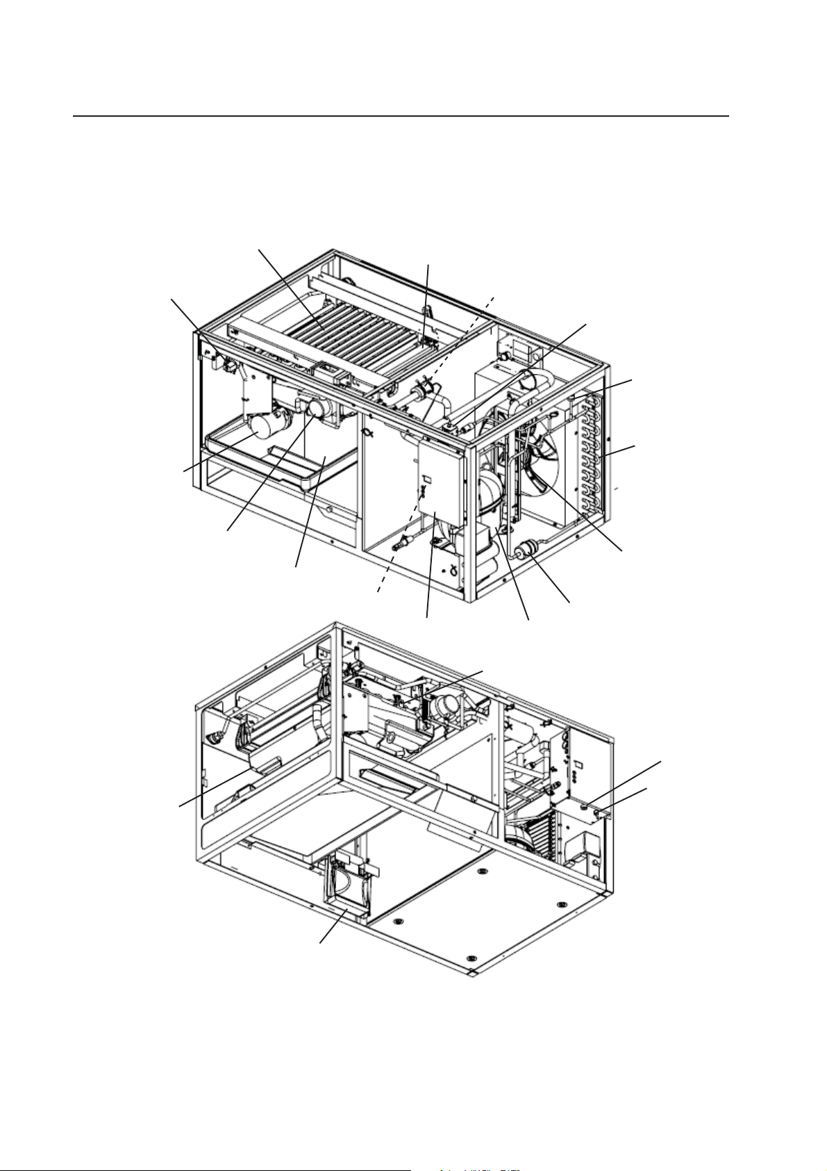
I. Construction and Water/Refrigeration Circuit Diagram
A. Construction
1. Air-Cooled Model (SAA)
Inlet Water Valve
Pump Motor
Actuator Motor
Evaporator
Drain Pan
Control Board Thermistor
Water Plate
Control Box
Thermostatic Expansion Valve
Hot Gas Valve
High-Pressure
Switch
Condenser
Fan Motor
Drier
Compressor
Water Tank
Evaporator Thermistor
Fuse Holder
Control
Switch
Bin Control
Model Shown: IM-500SAA
6
Page 7

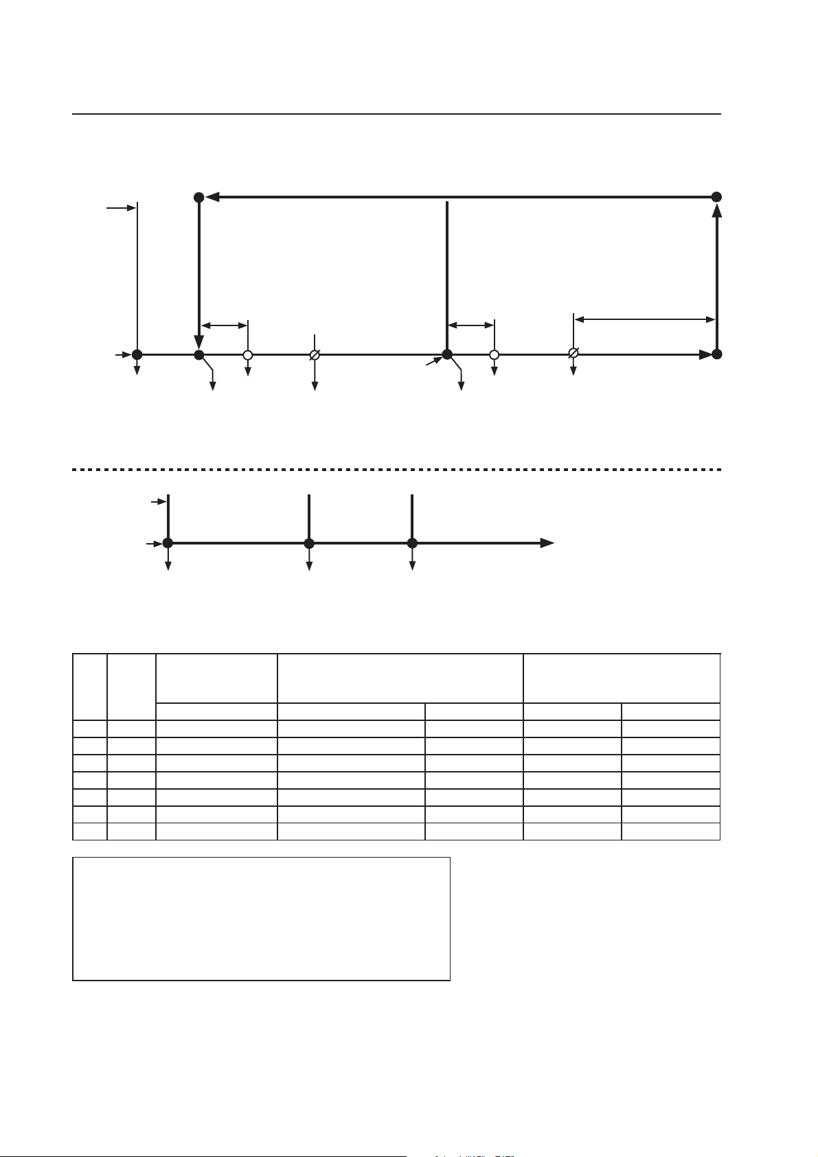
B. Water/Refrigeration Circuit Diagram
1. Air-Cooled Model (SAA)
Inlet
Water
Valve
Thermostatic Expansion Valve
Evaporator
Evaporator Thermistor
Hot Gas
Valve
Strainer
Water
Pump
Condenser
Fan Motor
Compressor
Water Tank
Heat Exchanger
Drier
Water Circuit
Refrigerant Circuit
7
Page 8
II. Sequence of Operation and Service Diagnosis
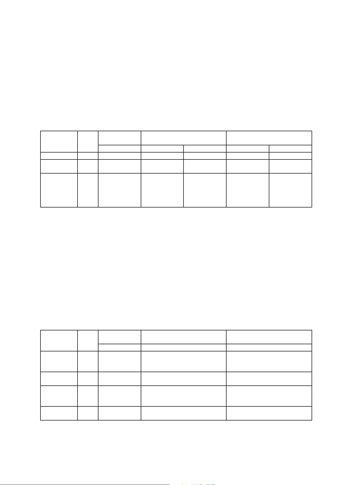
A. Sequence of Operation Flow Chart
"IM" Control Board
Cycle
Steps
Startup
HGV energized
Shutdown and Restart Sequence Flow Chart
Shutdown
and Restart
BC Operation
1. 30-Sec.
Startup
Cycle
1. Bin Full
2. Harvest Cycle
• HGV: If CBT≤81°F (27°C) (CB Setting
74), HGV repeatedly energizes 40sec./
de-energizes 40 sec.
• FM: If CBT≥118°F (48°C) (CB Setting 34),
FM operates continuously in harvest cycle
• Max. harvest time: 30 min.
WV Delay PM Delay
*1
WV energized *2
HGV continues
AMD energized
Comp energized
ET≥41°F (5°C)
(CB Setting 1)
Water Tank Closed
(Actuator Motor PS)
Comp continues
AMU energized
FM energized
WV energized *3
HGV de-energized
2. Icemaker Off
3. Freeze Cycle
• Max. freeze time: 45 min. (CB Setting 6)
*4
PM energized
Comp continues
FM continues
WV energized *4+*5
3. Ice Level Lowered
ET≤-1.3°F (-18.5°C)
(CB Setting 2)
Time varies based on
control board calculation
If CBT>81°F (27°C) (CB
Setting 74) and CBT≤111°F
(44°C) (CB Setting 70), HGV
energizes 5sec./de-energizes
25 sec./energizes 5 sec. (CB
Setting 71, 72)
Icemaker restarts at
1.30-Sec. Startup Cycle.
Note
CB
Setting
BC open 10 sec. or more
(BC actuator paddle
engaged). Shutdown
occurs at end of harvest
cycle.
Initial Harvest and
Initial Freeze after
Power On
All components
de-energized.
BC closed 80 sec. or more
(BC actuator paddle
disengaged).
Initial Harvest and Initial Freeze after
Bin Control Initiated Restart
Normal Harvest and Freeze
All WT WT>48°F (9°C) WT≤48°F (9°C) WT>48°F (9°C) WT≤48°F (9°C)
*1 NA 20 sec. 0 sec. 0 sec. 20 sec. 20 sec.
*2 10, 11 95 sec. 10 sec. (CB Setting NA) 95 sec. 30 sec. 95 sec.
*3 NA 10 sec. 0 sec. 10 sec. 0 sec. 10 sec.
PD*4 12 30 sec. × 2 30 sec. × 2 30 sec. × 2 30 sec. 30 sec.
PD*5 15 22 sec. × 2 22 sec. × 2 22 sec. × 2 22 sec. 22 sec.
FD*4 12 60 sec. 60 sec. 60 sec. 60 sec. 60 sec.
FD*5 15 44 sec. 44 sec. 44 sec. 44 sec. 44 sec.
Legend:
AMD–actuator motor down
AMU–actuator motor up
BC–bin control
CBT–control board thermistor
Comp–compressor
ET–evaporator thermistor
FD–full drain (CB Setting 14)
FM–fan motor
HGV–hot gas valve
PD–partial drain (CB Setting 14)
PM–pump motor
PS–position sensor
WT–water temperature
WV–inlet water valve
8
Page 9
B. Sequence of Operation
1. Startup Cycle
When power supply is turned on, "on" appears on CB display and HGV energizes.
30sec. later, harvest cycle starts.
• If the "RESET" button is pressed during 30-sec. startup cycle time, startup cycle ends
immediately and harvest cycle starts.
2. Harvest Cycle
HGV continues. Comp and AMD energize. WV energizes as listed in table below.
Initial Harvest
CB
Note
WV Delay NA 20 sec. 0 sec. 0 sec. 20 sec. 20 sec.
WV Time after
WV Delay
WV Time
when
ET≥41°F
(5°C)
(CB Setting 1)
Setting
10, 11 95 sec. 10 sec.
NA 10 sec. 0 sec. 10 sec. 0 sec. 10 sec.
after Power On
All WT WT>48°F (9°C) WT≤48°F (9°C) WT>48°F (9°C) WT≤48°F (9°C)
Initial Harvest after Bin Control
Initiated Restart
95 sec. 30 sec. 95 sec.
(CB Setting NA)
Normal Harvest
Note: ET temperature is recorded 30 seconds after PM energizes in the preceding
freeze cycle. Water temperature correction value (CB Setting 13) is added to ET
temperature and this is used as WT value.
If CBT≤81°F (27°C) (CB Setting 74) at beginning of harvest cycle, HGV repeatedly
energizes 40sec./de-energizes 40 sec. If CBT≥118°F (48°C) (CB Setting 34) at
beginning of harvest cycle, FM operates continuously in harvest cycle.
When ET reaches harvest cycle termination temperature (CB Setting 1) of 41°F (5°C) ,
HGV de-energizes, FM and AMU energize. Comp continues. WV energizes as listed in
table above. Harvest cycle is complete when actuator motor PS indicates water tank is
fully closed.
3. Freeze Cycle
Comp and FM continue. WV energizes for total time of WV Time 1 and WV Time 2 listed
in table below. PM energizes after PM delay listed in table below.
Note
PD
WV Time 1
and PM Delay
PD
WV Time 2
FD
WV Time 1
and PM Delay
FD
WV Time 2
CB
Setting
12 30 sec. × 2 30 sec. × 2 30 sec.
15 22 sec. × 2 22 sec. × 2 22 sec.
12 60 sec. 60 sec. 60 sec.
15 44 sec. 44 sec. 44 sec.
Initial Freeze
after Power On
All WT All WT All WT
Initial Freeze after Bin Control
Initiated Restart
Normal Freeze
9
Page 10

ET temperature is recorded 30 seconds after PM energizes. Water temperature
correction value (CB Setting 13) is added to ET temperature and this is used as WT
value in following harvest cycle.
If CBT>81°F (27°C) (CB Setting 74) and CBT≤111°F (44°C) (CB Setting 70), when
ET≤-1.3°F (-18.5°C) (CB Setting 2), HGV energizes 5 sec., de-energizes 25 sec.,
energizes 5 sec. (CB Settings 71 and 72) to reduce bonding of the water tank to the
evaporator.
CB monitors time after ET temperature≤32°F (0°C). CB terminates freeze cycle when the
following equation is satised:
temp. (absolute value) × time (min.) = (absolute value of CB Setting 2) × (CB Setting 3)
Using default settings, freeze cycle is terminated when:
temp. (absolute value) × time (min.) = 185
This formula helps maintain consistent dimple size regardless of differences in seasonal
ambient and water temperatures.
4. Shutdown
When BC is engaged (open) for more than 10 seconds, the icemaker shuts down after
harvest cycle.
When BC is disengaged (closed) for more than 80 seconds, icemaker restarts at startup
cycle.
If BC is engaged (open) while the water tank is opening after the power supply is turned
on (or after the "RESET" button is pressed), shutdown does not start: Shutdown occurs
10seconds after actuator motor's internal position sensor indicates water tank is fully
open.
Legend: AMD–actuator motor down; AMU–actuator motor up; BC–bin control; CB–control
board; CBT–control board thermistor; Comp–compressor; ET–evaporator
thermistor; FD–full drain (CB Setting 14); FM–fan motor; HGV–hot gas valve;
PM–pump motor; PD–partial drain (CB Setting 14); PS–position sensor; WT–water
temperature; WV–inlet water valve
10
Page 11
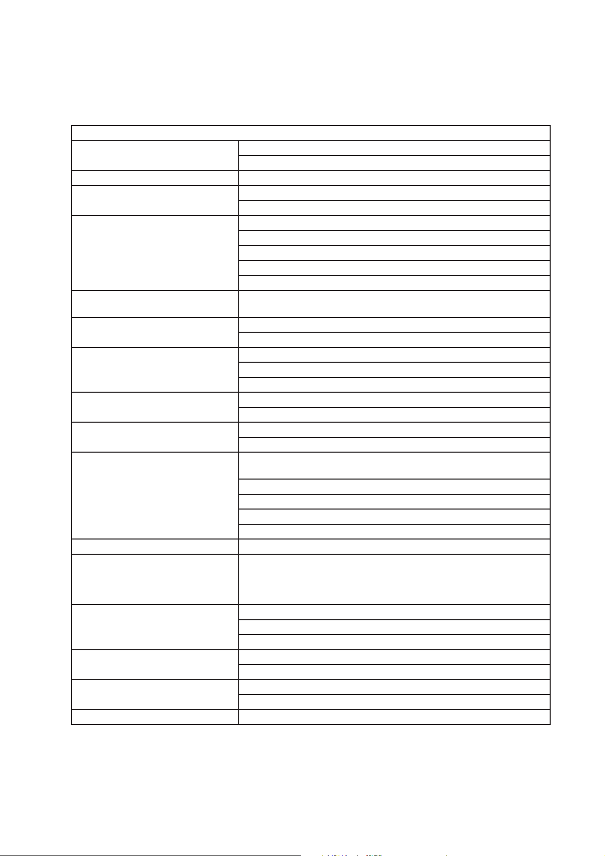
C. Service Diagnosis Table
First see "III.G. Error Codes." If there are no recorded errors, refer to the table below.
No Ice Production - Possible Cause
1. Power Supply a) Off, blown fuse, or tripped breaker.
b) Not within specications.
2. Fuse (Control Box) a) Blown.
3. Control Switch a) In "OFF" or "WASH" position.
b) Bad contacts.
4. High-Pressure Switch a) Dirty condenser or air lter.
b) Fan motor not operating.
c) Refrigerant overcharged.
d) Bad contacts.
e) Refrigerant lines or components restricted.
5. Control Transformer
(115VAC/10.5VAC)
6. Control Board a) Error. See "III.G. Error Codes."
7. Bin Control
See "II.D. Bin Control Check and
Cleaning"
8. Water Supply a) Water supply off or improper water pressure.
9. Inlet Water Valve a) Screen or orice restricted.
10. Compressor a) Compressor relay/magnetic contactor contacts bad or coil winding
11. Hot Gas Valve a) Defective.
12. Evaporator (Cube Control)
Thermistor
See "II.E. Evaporator Thermistor
Check"
13. Pump Motor a) Mechanical seal worn out.
14. Thermostatic Expansion Valve a) Bulb loose.
15. Fan Motor a) Defective.
16. Water System a) Water leaks.
a) Coil winding open or shorted.
b) Defective.
a) Tripped with bin lled with ice.
b) Actuator does not move freely.
c) Defective.
b) External water lters restricted.
b) Coil winding open.
open.
b) Start capacitor or run capacitor defective (single phase).
c) Internal protector open.
d) Start relay contacts bad or coil winding open (single phase).
e) Defective.
a) Loose, disconnected, or defective.
b) Defective.
c) Defective capacitor.
b) Defective.
b) Defective capacitor.
11
Page 12
Low Ice Production - Possible Cause
Long Harvest Cycle
1. Evaporator a) Scaled up.
2. Refrigerant Charge a) Low.
3. Control Board a) Thermistor connection loose (K3).
b) Defective.
4. Evaporator (Cube Control)
Thermistor
See "II.E. Evaporator Thermistor
Check"
5. Hot Gas Valve a) Erratic or closed.
6. Compressor a) Inefficient or off.
7. Thermostatic Expansion Valve a) Defective.
1. Evaporator a) Scaled up, dirty.
2. Hot Gas Valve a) Defective.
3. Condenser a) Restricted.
4. Control Board a) Defective.
5. Refrigerant Charge a) Low.
6. Thermostatic Expansion Valve a) Bulb loose.
7. Compressor a) Inefficient or off.
a) Loose, disconnected, or defective.
Long Freeze Cycle
b) Defective.
Slab Does Not Break Into Separate Cubes - Possible Cause
1. Spring a) Over-extended.
2. Water Plate a) Obstacle caught between evaporator and water plate.
Cubes Drop Separately - Possible Cause
1. Refrigerant Charge a) Low - Long harvest cycle.
2. Cam Arm a) Worn out.
Imperfect Ice Production - Possible Cause
1. Water Supply a) Improper water pressure.
b) External water lters restricted.
c) Water leaks from water tank or water plate due to broken tank or
plate or icemaker out of level.
2. Inlet Water Valve a) Water leaks from valve body or water supply pipe joint.
3. Water Plate a) Spray holes restricted.
4. Pump Motor a) Defective.
Large-Hole Cubes - Possible Cause (Also see III.H.1. Dimple Diameter")
1. Refrigerant Charge a) Low.
2. Condenser a) Dirty condenser or air lter.
3. Fan Motor a) Defective.
12
Page 13

Large-Hole Cubes - Possible Cause (Also see III.H.1. Dimple Diameter")
4. Icemaker Location a) Insufficient clearance.
b) Ambient temperature too high.
5. Water Supply a) Water leaks.
b) Improper water pressure.
Cloudy Cubes - Possible Cause
1. Water Quality a) High hardness. See "III.H.2. Ice Clarity."
2. Slush Ice a) Use Anti-Slush Control (Control Board Settings 50 and 51).
13
Page 14

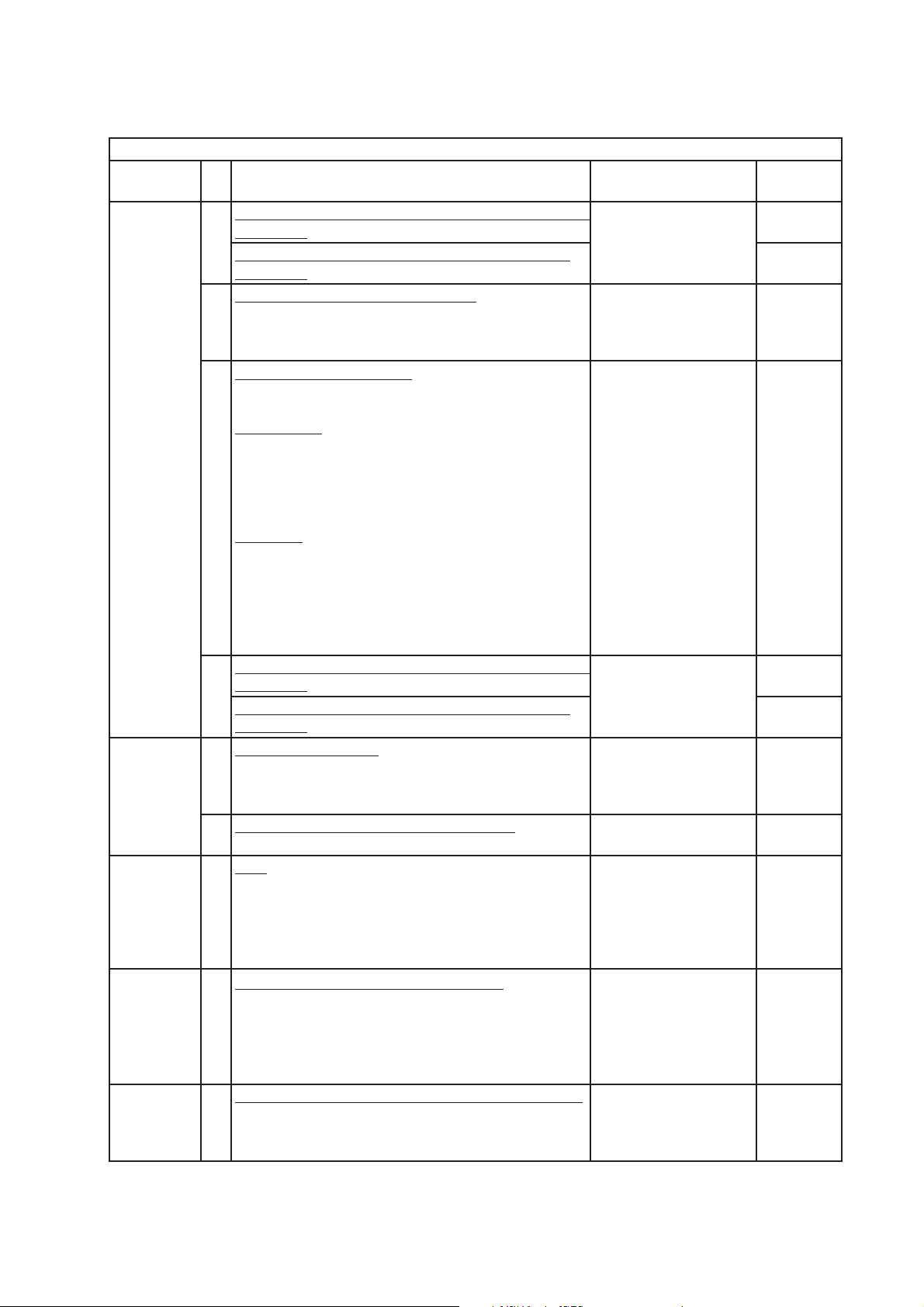
D. Bin Control Check and Cleaning
1. Bin Control Check
This appliance uses a lever-actuated proximity switch to control the ice level in the
storage bin. No adjustment is required.
To check, follow the steps below.
1) Turn off the power supply.
2) Remove the front panel, then move the control switch to the "OFF" position.
3) Remove the control box cover. Clear any ice away from BC.
4) Check BC wire harness connections.
5) Disconnect BC wire harness connector from CB CN11 connector.
6) Check for continuity across the wires of BC wire harness connector. When the actuator
paddle is not engaged, BC switch is closed. If open, check that the wire harness
connector is properly connected and that the actuator paddle is not sticking. Clean if
necessary. See "II.D.2. Bin Control Cleaning." If BC switch still reads open, replace BC.
7) Press and hold the actuator paddle; check for continuity across the wires of BC wire
harness connector. When the actuator paddle is engaged, BC switch is open. If closed,
check that the actuator paddle is not restricted. Clean if necessary. See "II.D.2. Bin
Control Cleaning." If BC switch still reads closed, replace BC.
8) Reconnect BC wire harness connector to CB CN11 connector, then move the control
switch to the "ICE" position. Turn on the power supply.
9) Allow the icemaker to cycle on. Press and hold the actuator paddle for at least
10seconds. The icemaker should shut down. If it does not, replace CB.
Note: If BC is engaged (open) while the water tank is opening after the power supply
is turned on (or after the "RESET" button is pressed), shutdown does not start:
Shutdown occurs 10seconds after actuator motor's internal position sensor
indicates water tank is fully open.
Legend: BC–bin control; CB–control board
Bin Control Bracket
Thumbscrew
Bin Control Cable Connector
Fig. 1
Bin Control
Switch Mount
Actuator Paddle
14
Magnet
Page 15

2. Bin Control Cleaning
Scale may build up on BC. Scale can cause the actuator paddle and magnet to stick. In
this case, BC should be cleaned.
WARNING
CHOKING HAZARD: Ensure all components, fasteners, and thumbscrews are
securely in place after the icemaker is serviced. Make sure that none have fallen
into the dispense unit/ice storage bin.
1) Turn off the power supply.
2) Remove the front panel, then move the control switch to the "OFF" position.
3) Clear any ice away from BC.
4) Carefully remove the BC cable from the cable ties in the evaporator case, then remove
the BC from the bin control bracket and move to the front of the icemaker for cleaning.
5) Remove the actuator paddle from the switch mount. See Fig. 1.
6) Wipe down BC with a mixture of 1 part of Hoshizaki "Scale Away" and 25 parts of warm
water. Rinse the parts thoroughly with clean water.
7) Reassemble BC and replace it in its correct position.
Note: If the magnet was removed for cleaning, be sure to replace it in its correct
position.
8) Replace the BC cable into the cable ties in the evaporator case, then move the control
switch to the "ICE" position.
9) Conrm CB wire harness connections are secure, then replace the control box cover in
its correct position.
10) Turn on the power supply to start the automatic icemaking process.
11) Replace the front panel in its correct position.
Legend: BC–bin control; CB–control board
15
Page 16

E. Evaporator Thermistor Check
To check thermistor resistance, follow the steps below.
1) Turn off the power supply.
2) Remove the front panel. Move the control switch to the "OFF" position.
3) Remove the control box cover.
4) Remove the thermistor from the evaporator.
5) Immerse the thermistor sensor portion in a glass containing ice and water for 2 or 3 min.
6) Disconnect the thermistor connector from CB CN13 connector and check the resistance
between thermistor leads. Normal range is 4.7 to 6.2 kΩ. If outside the normal range,
replace the thermistor. See "IV.B. Component Service Information." If within the normal
range, continue to the next step.
7) Replace the thermistor in its correct position. See "IV.B. Component Service
Information."
8) Reconnect the thermistor connector to CB CN13 connector.
9) Replace the control box cover in its correct position.
10) Move the control switch to the "ICE" position.
11) Replace the front panel in its correct position.
12) Turn on the power supply.
Legend: CB–control board; Comp–compressor
16
Page 17

III. Controls and Adjustments
A. Control Switch
The control switch has three positions: OFF for power off, ICE for icemaking, and WASH
to energize the water pump when cleaning and sanitizing.
B. Control Board
• A Hoshizaki exclusive control board is employed in IM series appliances.
• All models are pretested and factory adjusted.
NOTICE
• Fragile, handle very carefully.
• The control board contains integrated circuits, which are susceptible to failure
due to static discharge. It is especially important to touch the metal part of the
icemaker when handling or replacing the control board.
• Do not touch the electronic devices on the control board or the back of the control
board.
• Do not change wiring and connections.
• Do not short out power supply to test for voltage.
• Always replace the whole control board assembly if it goes bad.
17
Page 18

1. Control Board Layout
• CN9 Connector
Display Output
• RESET Button
• SERVICE 1 Button
• SERVICE 2 Button
• CN16 Connector
Actuator Motor Position Sensor (Hall IC) Input
• CN11 Connector
Bin Control Input
• CN13 Connector
Evaporator (Cube Control) Thermistor Input
• CN10 Connector
Compressor Start DC Relay Drive Output
• CN4 Connector
Data Input/Output
• CN1 Connector
Control Transformer (10.5VAC) Input
• CN2 Connector
115VAC Input
• F1 Fuse
6.3A, 250VAC
• CN3 Connector
• CN5 Connector
Actuator Motor Output
115VAC Output: Pump Motor; Hot Gas Valve;
Fan Motor; Inlet Water Valve; Compressor Relay
"IM" Control Board
Part Number P01873-01 Version 1.3A or Later
18
Page 19

C. Control Buttons
The control board features RESET, SERVICE 1, and SERVICE 2 Buttons
1. RESET Button
• Press briey to go to initial harvest cycle.
• Press and hold for 3 seconds to enter control board setting mode. For details about
control board settings, see "III.D. Control Board Setting Mode and Control Board
Settings."
2. SERVICE 1 and SERVICE 2 Buttons
• Press the "SERVICE 1" or "SERVICE 2" button briey to display the current freeze
cycle termination temperature (Control Board Setting 2). This setting controls dimple
diameter. For details about adjusting the dimple diameter, see "III.H.1. Dimple
Diameter." NOTICE! Do not decrease dimple size below 3/16" (5 mm).
• Press and hold the "SERVICE 1" button for 3 seconds to enter information display and
model code setting mode. For details about information display and model code setting,
see "III.F. Model Code Setting Mode."
19
Page 20

D. Control Board Settings
NOTICE
Failure to maintain factory settings may adversely affect performance and warranty
coverage. For more information, contact your Hoshizaki Service Center.
1) With "on" in display, press and hold the "RESET" button for 3 seconds. Display changes
to "1".
2) Use the "SERVICE 1" and "SERVICE 2" buttons to choose a control board setting.
3) Press the "RESET" button to view the setting’s value. Current value ashes in display.
4) Use the "SERVICE 1" and "SERVICE 2" buttons to change value.
5) Press the "RESET" button to select value. Display returns to control board setting
number.
6) Once display returns to "on" (20 seconds), the new setting is saved.
Control Board (CB) Setting Menu
IM-500SAA
Category No. Item Range
Basic 1
Water
Supply
Harvest Cycle Termination Temperature
Temperature to complete harvest cycle.
2
Freeze Cycle Termination Temperature
Integrated with freeze cycle termination time (CB
Setting 3) to control length of freeze cycle after
evaporator (cube control) thermistor temperature
drops to 32°F (0°C). To use this setting for dimple
size adjustment, see "III.H.1. Dimple Diameter."
Freeze Cycle Termination Time
3
Integrated with freeze cycle termination temperature
(CB Setting 2) to control length of freeze cycle after
evaporator (cube control) thermistor temperature
drops to 32°F (0°C).
Ambient Temperature Correction Value for Freeze
4
Cycle Termination
DO NOT ADJUST
Ambient Temperature Correction Rate for Freeze
5
Cycle Termination
DO NOT ADJUST
Freeze Cycle Backup Timer
6
Maximum allowed freeze time to prevent possible
freeze-up issues.
Harvest Cycle Water Supply Time: Water
10
Temperature 48°F (9°C) or Lower
When set to "99", inlet water valve energized until
harvest cycle termination temperature (CB Setting 1)
is reached.
Harvest Cycle Water Supply Time: Water
11
Temperature Higher Than 48°F (9°C)
When set to "99", inlet water valve energized until
harvest cycle termination temperature (CB Setting 1)
is reached.
2 to 20°C
(1°C increments)
-5 to -40°C
(0.5°C increments. The
"." in the lower, right
corner of the display
indicates .5°C.)
5 to 90 min.
(1 min. increments)
10 to 50°C
(1°C increments)
10 to 100% (00 = 100)
(1% increments)
45 to 90 min.
(5 min. increments)
1 to 99 sec,
99 = continuous
(1 sec. increments)
1 to 99 sec,
99 = continuous
(1 sec. increments)
Default
5
-18.5
10
10
100
45
95
30
20
Page 21
Control Board (CB) Setting Menu
Category No. Item Range
Water
Supply,
continued
Other 21
Model 30
Harvest
Cycle High
Temperature
Control
Water
Regulating
Valve
12
Freeze Cycle Water Supply Time 1: Partial Drain (CB
Setting 14)
Freeze Cycle Water Supply Time 1: Full Drain (CB
Setting 14)
Water Temperature Correction Value
13
Value added to correct the difference between
the temperature at the evaporator (cube control)
thermistor and actual water supply temperature.
Partial/Full Drain Selection
14
Controls timing for inlet water valve and pump motor
in the freeze cycle.
Partial Drain: Pump motor energizes after freeze
cycle water supply time 1 (CB Setting 12) timer
terminates. During the rst freeze cycle after startup
or following a bin control initiated shutdown and
restart, freeze cycle water supply times 1 and 2 (CB
Settings 12 and 15) are doubled.
Full Drain: Pump motor energizes after freeze cycle
water supply time 1 (CB Setting 12) timer terminates.
If full drain is selected, change freeze cycle making
water supply times 1 and 2 (CB Settings 12 and 15)
to the full drain times listed in this table and move
the water tank drain pipe to the drain position. For
details, see "III.H.2. Ice Clarity."
Freeze Cycle Water Supply Time 2: Partial Drain (CB
15
Setting 14)
Freeze Cycle Water Supply Time 2: Full Drain (CB
Setting 14)
Stackable Bin Control
Allows for stacked units to be controlled through one
bin control.
DO NOT ADJUST
Refrigeration Circuit Cycling when Bin Full
22
DO NOT ADJUST
Type
0: WC, PS, No CondTherm, Ignore CB Setting 34
1: AC, No PS, No CondTherm, Use CB Setting 34
2: AC, No PS, CondTherm, Use CB Setting 34
3: AC, PS, No CondTherm, Use CB Setting 34
DO NOT ADJUST
34
Harvest Cycle High Temperature Control
Active if type setting (CB Setting 30) is set to 1, 2,
or 3. If control board thermistor temperature at the
beginning of harvest cycle is equal to or greater than
the harvest cycle high temperature control setting,
fan motor operates continuously in harvest cycle.
Water Regulating Valve Error Detection Temperature
36
DO NOT ADJUST
0 to 90 sec.
(1 sec. increments)
+0 to +20°C
(1°C increments)
Partial=1; Full=0 1
0 to 90 sec.
(1 sec. increments)
Yes=1; No=0 1
On=1; Off=0 0
0 to 3 3
40 to 70°C
(1°C increments)
0 to 50°C
0=ignore, air-cooled
model
(1°C increments)
IM-500SAA
Default
30
60
11
22
44
48
0
21
Page 22

Control Board (CB) Setting Menu
Category No. Item Range
Compressor 37
Anti-Slush
Control
Hard Water
Control
Water Tank
Ice Control7071
Water Tank
Ice Control
& Ice Bridge
Control
Water Tank
Ice Control
Ice Bridge
Control
Compressor Output Selection
DO NOT ADJUST
Pump De-Energized Time
50
When temperature at evaporator (cube control)
thermistor drops to 37°F (3°C) in the freeze cycle,
pump de-energizes for the length of time set.
Anti-Slush Control Water Supply Time
51
Time inlet water valve is energized while pump is
de-energized if pump de-energized time (CB Setting
50) is greater than 0.
Integrated Value
60
If hard water control water supply time (CB Setting
61) is greater than 0: After evaporator (cube control)
thermistor indicates temperature of 32°F (0°C) in
freeze cycle, inlet water valve energized starting
when percentage of freeze cycle termination
temperature and freeze cycle time integrated value
has been achieved.
DO NOT ADJUST
Hard Water Control Water Supply Time
61
Time inlet water valve is energized after integrated
value (CB Setting 60) conditions are met.
Before using this setting, follow the instructions to
improve ice clarity; see "III.H.2. Ice Clarity."
If control board thermistor temperature is above
the water tank ice control lower temperature setting
72
(CBSetting 74) and equal to or less than the
74
water tank ice control upper temperature setting
(CB Setting 70) when freeze cycle termination
temperature (CB Setting 2) is met, the hot gas valve
energizes/de-energizes/energizes for the times set
by the hot gas valve energized/de-energized times
(CB Settings 71 and 72) to reduce bonding of the
water tank to the evaporator.
Water Tank Ice Control Upper Temperature
70
See CB Setting 70, 71, 72, 74 description above.
Ice Bridge Control Temperature
See CB Setting 73 description below.
Water Tank Ice Control Hot Gas Valve Energized
71
Time
See CB Setting 70, 71, 72, 74 description above.
Water Tank Ice Control Hot Gas Valve De-Energized
72
Time
See CB Setting 70, 71, 72, 74 description above.
Ice Bridge Control Hot Gas Valve De-Energized Time
73
Time hot gas valve is de-energized after 20 sec. in
harvest cycle if control board thermistor temperature
is above the ice bridge control temperature
(CBSetting 70) when freeze cycle termination
temperature (CB Setting 2) is met.
0: X8 (DC Relay) On
1: X1 (AC Relay) On
0 to 90 sec.
0=ignore, no anti-slush
(1 sec. increments)
0 to 5 sec.
(1 sec. increments)
10 to 100%
(00=100)
(1% increments)
0 to 90 sec.
(1 sec. increments)
See Ranges Below See
10 to 60°C
(1°C increments)
0 to 20 sec.
(1 sec. increments)
10 to 60 sec.
(1 sec. increments)
0 to 30 sec.
(1 sec. increments)
IM-500SAA
Default
1
0
0
10
0
Defaults
Below
44
5
25
0
22
Page 23

Control Board (CB) Setting Menu
IM-500SAA
Category No. Item Range
Water Tank
Ice Control
& Harvest
Cycle Low
Temperature
Control
Water Tank Ice Control Lower Temperature
74
See CB Setting 70, 71, 72, 74 description above.
Harvest Cycle Low Temperature Control
If control board thermistor temperature at the
beginning of harvest cycle is equal to or less than
the harvest cycle low temperature control setting, hot
gas valve repeatedly energizes for 40 seconds then
de-energizes for 40 seconds to promote a balanced
harvest across the evaporator plate.
0 to 40°C
(1°C increments)
Default
27
E. Control Board Information Display
1. With unit on, press and hold the "SERVICE 1" button for 3 seconds. Display changes to
"n1".
2. Use the "SERVICE 1" and "SERVICE 2" buttons to move through the list.
3. Press the "RESET" button to view the item’s value.
4. Press the "RESET" button to return to list.
5. Display returns to normal if no buttons are touched for 20 seconds.
Control Board Information Display
No. Item Description
Freeze Cycle Time
n1
During Freeze Cycle: Time since freeze cycle
started.
After Freeze Cycle: Time of previous freeze cycle.
Freeze Cycle Completion Rate
n2
During Freeze Cycle: Percent of freeze cycle
completed.
After Freeze Cycle: Percent of previous freeze
cycle completed.
Current Evaporator (Cube Control) Thermistor
n3
Temperature
Current Control Board Thermistor Temperature °C No
n4
n5
Water Temperature
Temperature at evaporator (cube control)
thermistor 30 seconds after pump motor
energized in freeze cycle plus the water
temperature correction value (Control Board
Setting 13).
Current Condenser Thermistor Temperature
n6
Not Applicable to IM-500SAA
0 to 99 min. No
0 to 100%
00 = 100%
°C No
"H" if Higher than 48°F
(9°C)
"L" if 48°F (9°C) or
Lower
°C No
History Cleared by
Pressing and Holding
SERVICE 1 and
SERVICE 2 Buttons
Simultaneously for
5Sec. when Item Value
is Displayed?
No
No
23
Page 24

Control Board Information Display
No. Item Description
Last Completed Freeze Cycle Time
h1
Freeze cycles interrupted by bin control shutdown
or the "RESET" button are not recorded.
Number of Completed Freeze Cycles Since Last
h2
Counter Reset
Counter updates every 10 freeze cycles. Freeze
cycles interrupted by bin control shutdown or the
"RESET" button are not recorded.
Total Number of Completed Freeze Cycles
h3
Counter updates every 10 freeze cycles. Freeze
cycles interrupted by bin control shutdown or the
"RESET" button are not recorded.
Error Log
h4
Displays up to 5 errors with the most recent error
rst. For error details, see "III.G. Error Codes."
Firmware Version
h5
Displays control board's rmware version.
Model Code
h6
The model code puts all settings for a given
model to the correct default settings. The model
code setting mode should only be used when the
control board has been changed, the model code
is incorrect, or to reset all settings to the default.
For details about the model code setting mode,
see "III.F. Model Code Setting Mode."
0 to 99 min. Yes
Displays up to 999,999
cycles. Displays two
digits at a time. For
example, 655,350 cycles
display as follows:
65>off>53>off>50>off>- (repeat)
For example, E5 (most
recent), E4, E3, E2,
E1 (least recent of up
to 5 errors) displays as
follows:
E5>off>E4>off>E3>off>E
2>off>E1>off>- - (repeat)
For example, version
1.0A, displays as follows:
01.>off>0A>off>- (repeat)
Displays two-character
model code.
"00" to "FF"
History Cleared by
Pressing and Holding
SERVICE 1 and
SERVICE 2 Buttons
Simultaneously for
5Sec. when Item Value
is Displayed?
Ye s
No
Ye s
No
No
24
Page 25

F. Control Board Model Code Setting
1. Control Board Replacement
WARNING
• This appliance should be diagnosed and repaired only by qualied service
personnel to reduce the risk of death, electric shock, serious injury, or re.
• Move the control switch to the "OFF" position and turn off the power supply. Place
the disconnect in the "OFF" position. Lockout/Tagout to prevent the power supply
from being turned back on inadvertently.
1) Move the control switch to the "OFF" position and turn off the power supply. Place the
disconnect in the "OFF" position. Lockout/Tagout to prevent the power supply from
being turned back on inadvertently.
2) Remove the front cover and control box cover.
3) Disconnect all the connectors from the control board.
4) Remove the old control board and install the new control board (
or Later).
5) Connect the connectors to the new control board.
6) Replace the control box cover in its correct position.
7) Turn on the power supply, then move the control switch to the "ICE" position.
8) "00" appears in the display of the new control board.
9) Press the "SERVICE 1" button to increase the rst digit in the display and the
"SERVICE2" button to increase the second digit. Digits appear in the following order:
0, 1, 2, 3, 4, 5, 6, 7, 8, 9, A, B, C, D, E, F. When a valid model code is displayed, the dot
in the bottom right of the display turns on. For IM-500SAA, set model code to "08".
10) When the desired model code is displayed, press the "RESET" button to save the
setting. "on" appears in the display.
11) Replace the front panel in its correct position.
2. Checking or Changing the Control Board Model Code
1) With unit on, press and hold the "SERVICE 1" button for 3 seconds. Display changes to
"n1".
2) Use the "SERVICE 1" and "SERVICE 2" buttons to move through the list until "h6" is
displayed.
P01873-01 Version 1.3A
3) Press the "RESET" button to view the current model code. To change the model code,
continue through the remaining steps; otherwise, the display returns to normal if no
buttons are touched for 20 sec.
4) Press and hold the "SERVICE 1" and "SERVICE 2" buttons simultaneously for 15 sec.
"00" appears in display.
25
Page 26

5) Press the "SERVICE 1" button to increase the rst digit in the display and the
"SERVICE2" button to increase the second digit. Digits appear in the following order:
0, 1, 2, 3, 4, 5, 6, 7, 8, 9, A, B, C, D, E, F. When a valid model code is displayed, the dot
in the bottom right of the display turns on. For IM-500SAA, set model code to "08".
6) When the desired model code is displayed, press the "RESET" button to save the
setting. "on" appears in the display.
26
Page 27

G. Error Codes
When the control board detects an error, the display shows one of the following error
codes in the display mode. Error codes other than E1 and E2 are displayed as "EE" at
the time of occurrence. To see the actual error code, see the error log.
1. With the unit on, press and hold the "SERVICE 1" button for 3 seconds. Display changes
to "n1".
2. Use the "SERVICE 1" and "SERVICE 2" buttons to move through the list until "h4" is
displayed.
3. Press the "RESET" button to view the error log. Displays up to 5 errors with the most
recent error rst.
4. Press the "RESET" button to return to list. To clear error log history, press and hold the
"SERVICE1" and "SERVICE 2" buttons simultaneously for 5 sec.
5. Display returns to normal if no buttons are touched for 20 sec.
Error Codes
Error
Code
E1
E2
EE
(E3)
EE
(E4)
Problem Corrective Action/Reset Details
Freeze Cycle Backup Timer
Freeze cycle backup timer (Control Board Setting
6) has terminated.
45 min. after water tank starts to close in
preceding harvest cycle, unit stops if the
evaporator temperature is above 32°F (0°C).
Harvest Cycle Backup Timer
Harvest cycle backup timer has terminated.
30 min. after water tank starts to open in harvest
cycle, unit stops if harvest cycle termination
temperature (Control Board Setting 1) has not
been reached.
Water Tank Opening Backup Timer
3-minute opening backup timer starts when water
tank starts to open.
If actuator motor's internal position sensor
does not indicate water tank is fully open within
3minutes, display shows "EE" and unit stops for
60 minutes.
If error recurs after unit resumes operation,
display shows "EE" and unit shuts down.
Water Tank Closing Backup Timer
3-minute closing backup timer starts when water
tank starts to close.
If actuator motor's internal position sensor does
not indicate water tank is fully closed within
3minutes, display shows "EE" and unit stops for
60 minutes.
If error recurs after unit resumes operation,
display shows "EE" and unit shuts down.
Check for inlet water valve leaking by, hot gas valve
leaking by, pump motor not pumping, thermostatic
expansion valve not feeding properly, low charge, or
inefficient compressor.
Press the "RESET" button to reset.
Check for open thermistor, HGV not opening, TXV
leaking by, low charge, or inefficient compressor.
Press the "RESET" button to reset.
Check actuator motor and control board.
Press the "RESET" button to reset.
Check actuator motor and control board.
Press the "RESET" button to reset.
27
Page 28

Error Codes
Error
Code
EE
(E5)
EE
(E9)
EE
(EA)
EE
(EC)
EE
(Ed)
Problem Corrective Action/Reset Details
High Evaporator Temperature
If evaporator temperature 140°F (60°C) or higher
for 5sec., unit stops.
Condenser Thermistor Error
If condenser thermistor is open or shorted for
2sec., unit stops.
Note: IM-500SAA does not utilize a condenser
thermistor, therefore E9 error will not occur.
Control Board Error
If model data IC is defective, unit stops.
Evaporator (Cube Control) Thermistor Error
If evaporator thermistor is open or shorted for
2sec., unit stops.
Water Regulating Valve Error
If water regulating valve thermistor detects a
temperature below the water regulating valve
error detection temperature (Control Board
Setting 36), error is displayed but unit continues
to operate.
Note: IM-500SAA does not utilize a water
regulating valve, therefore Ed error will not occur.
Check for harvest problem (stuck HGV or control
board relay), hot water entering unit, or shorted
thermistor.
Press the "RESET" button to reset.
Replace condenser thermistor.
Replace control board.
Replace evaporator thermistor.
Check water regulating valve.
Press the "RESET" button to reset.
H. Quick Adjustments
1. Dimple Diameter
The factory set dimple diameter is 3/16" (5 mm). NOTICE! Do not decrease the dimple
diameter below 3/16" (5 mm).
a) To increase dimple diameter:
1) Remove front panel.
2) Press the "SERVICE 1" button to view the current freeze cycle termination temperature
setting.
3) Press the "SERVICE 1" button to raise freeze cycle termination temperature setting
(Control Board Setting 2). Temperature setting rises in .5°C increments. The "." in the
lower, right corner of the display indicates .5°C. Default is -18.5°C. For reference, raising
freeze cycle termination temperature setting to -13°C will result in a dimple diameter of
approximately 3/8" (10mm).
4) Once the display returns to "on" (20 seconds), the new setting is saved.
b) To decrease dimple diameter:
1) Remove front panel.
2) Press the "SERVICE 2" button to view the current freeze cycle termination temperature
setting.
28
Page 29
3) Press the "SERVICE 2" button to lower freeze cycle termination temperature setting
(Control Board Setting 2). Temperature setting lowers in .5°C increments. The "." in the
lower, right corner of the display indicates .5°C. Default is -18.5°C. NOTICE! Do not
decrease dimple size below 3/16" (5 mm).
4) Once the display returns to "on" (20 seconds), the new setting is saved.
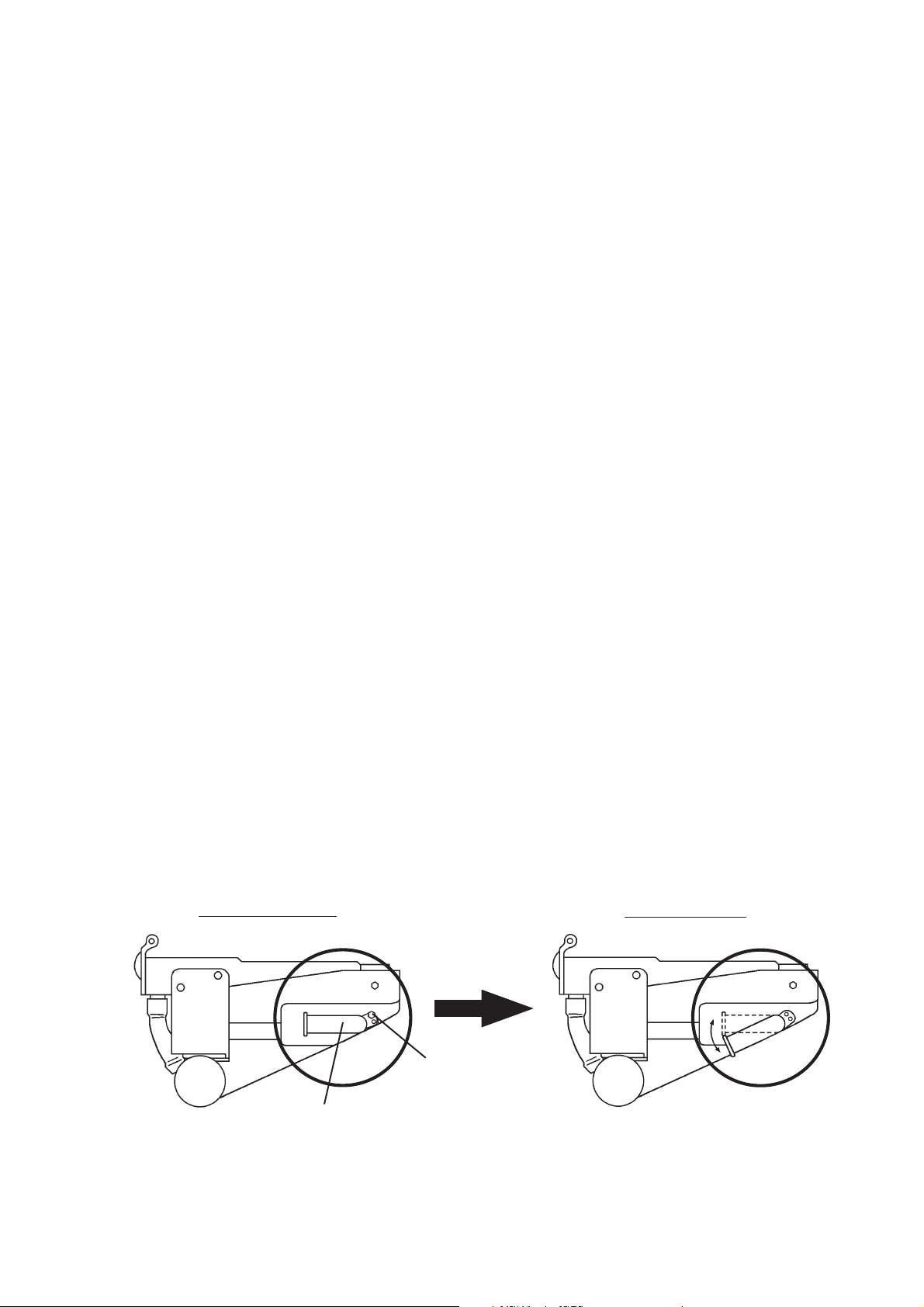
2. Ice Clarity
In hard water conditions, white ice may be produced. In such cases, install a water lter
and/or water softener, then follow the instructions below.
1) Move the control switch to the "OFF" position, then turn off the power supply.
2) Remove the front panel.
3) Remove the screw, then move the water tank drain pipe to the drain position. See Fig. 2.
Use the screw to secure the water tank drain pipe in the drain position.
4) Turn on the power supply, then move the control switch to the "ICE" position.
5) Press and hold the "RESET" button for 3 seconds. "1" appears in the display.
6) Press the "SERVICE 1" button until "12" appears in the display. Press the "RESET"
button. The current icemaking water supply time value ashes in the display. Press the
"SERVICE 1" or "SERVICE 2" buttons to change the setting to "60".
7) Press the "RESET" button to save the setting and return to the menu.
8) Using the same procedure as above, change the full/partial drain setting (Control Board
Setting 14) from "1" (partial drain) to "0" (full drain).
9) Using the same procedure as above, change the additional icemaking water supply time
setting (Control Board Setting 15) to "44".
10) Once the display returns to "on" (20 seconds), the new setting is saved.
11) Replace the front panel in its correct position.
Note: If white ice continues to be an issue, set hard water setting water supply time
(Control Board Setting 61) to "15". This results in the inlet water valve energizing
for 15 seconds part way through the freeze cycle and diluting the water in the
water tank. Do not increase this setting beyond 15 seconds; otherwise, freeze
cycle times may become long and bridging may occur in the ice storage bin.
Normal Position
Screw
Drain Position
Water Tank Drain Pipe
Fig. 2
29
Page 30

IV. Refrigeration Circuit and Component Service Information
WARNING
• This appliance should be diagnosed and repaired only by qualied service
personnel to reduce the risk of death, electric shock, serious injury, or re.
• Move the control switch to the "OFF" position and turn off the power supply. Place
the disconnect in the "OFF" position. Lockout/Tagout to prevent the power supply
from being turned back on inadvertently.
• CHOKING HAZARD: Ensure all components, fasteners, and thumbscrews are
securely in place after the icemaker is serviced. Make sure that none have fallen
into the dispenser unit/ice storage bin.
• Make sure all food zones in the icemaker and dispenser unit/ice storage bin are
clean after service.
A. Refrigeration Circuit Service Information
WARNING
• Repairs requiring the refrigeration circuit to be opened must be performed by
properly trained and EPA-certied service personnel.
• Use an electronic leak detector or soap bubbles to check for leaks. Add a trace of
refrigerant to the system (if using an electronic leak detector), and then raise the
pressure using nitrogen gas (140 PSIG). Do not use R-404A as a mixture with
pressurized air for leak testing.
NOTICE
• Always recover the refrigerant and store it in an approved container. Do not
discharge the refrigerant into the atmosphere.
• Do not leave the system open for longer than 15 min. when replacing or servicing
parts. The Polyol Ester (POE) oils used in R-404A applications can absorb
moisture quickly. Therefore it is important to prevent moisture from entering the
system when replacing or servicing parts.
• Always install a new drier every time the sealed refrigeration system is opened.
Do not replace the drier until after all other repair or replacement has been made.
Install the new drier with the arrow on the drier in the direction of the refrigerant
ow.
• When brazing, protect the drier by using a wet cloth to prevent the drier from
overheating. Do not allow the drier to exceed 250°F (121°C).
1. Refrigerant Recovery
The icemaker is provided with refrigerant access valves. Using proper refrigerant practices,
recover the refrigerant. Store the refrigerant in an approved container. Do not discharge the
refrigerant into the atmosphere.
30
Page 31

2. Brazing
WARNING
• R-404A itself is not ammable at atmospheric pressure and temperatures up to
176°F (80°C).
• R-404A itself is not explosive or poisonous. However, when exposed to high
temperatures (open ames), R-404A can be decomposed to form hydrouoric
acid and carbonyl uoride both of which are hazardous.
• Do not use silver alloy or copper alloy containing arsenic.
1) Braze all ttings while purging with nitrogen gas owing at a pressure of 3 to 4 PSIG.
Note: Because the pipes in the evaporator case are specially coated to resist corrosion,
it is important to make connections outside the evaporator case when possible. If
it is necessary to braze inside the evaporator case, use sandpaper to remove the
coating from the brazing connections before unbrazing the components.
NOTICE
• Always install a new drier every time the sealed refrigeration system is opened.
• Do not replace the drier until after all other repair or replacement has been made.
Install the new drier with the arrow on the drier in the direction of the refrigerant
ow.
• When brazing, protect the drier by using a wet cloth to prevent the drier from
overheating. Do not allow the drier to exceed 250°F (121°C).
2) Use an electronic leak detector or soap bubbles to check for leaks. Add a trace of
refrigerant to the system (if using an electronic leak detector), and then raise the
pressure using nitrogen gas (140 PSIG). Do not use R-404A as a mixture with
pressurized air for leak testing.
3. Evacuation and Recharge (R-404A)
1) Attach a vacuum pump to the system. Be sure to connect the charging hoses to both
high and low-side refrigerant access valves.
IMPORTANT
The vacuum level and vacuum pump may be the same as those for current
refrigerants. However, the rubber hose and gauge manifold to be used for
evacuation and refrigerant charge should be exclusively for POE oils.
2) Turn on the vacuum pump. Open the gauge manifold valves. Never allow the oil in the
vacuum pump to ow backwards.
3) Allow the vacuum pump to pull down to a 29.9" Hg vacuum. Evacuating period depends
on pump capacity.
4) Close the low-side valve and high-side valve on the gauge manifold.
31
Page 32

5) Disconnect the gauge manifold hose from the vacuum pump and attach it to a
refrigerant service cylinder. Remember to loosen the connection and purge the air
from the hose. For the required refrigerant charge, see the nameplate. Hoshizaki
recommends only virgin refrigerant or reclaimed refrigerant which meets ARI Standard
700 (latest edition) be used.
6) A liquid charge is required when charging an R-404A system (to prevent fractionation).
Place the service cylinder on the scales; if the service cylinder is not equipped with
a dip tube, invert the service cylinder, then place it on the scales. Open the high-side
valve on the gauge manifold.
7) Allow the system to charge with liquid until the proper charge weight is met.
8) If necessary, add any remaining charge to the system through the low-side.
NOTICE!To prevent compressor damage, use a throttling valve or liquid
dispensing device to add the remaining liquid charge through the low-side
refrigerant access valve with the icemaker running.
9) Close the high and low-side gauge manifold valves, then disconnect the gauge manifold
hoses.
10) Cap the refrigerant access valves to prevent a possible leak.
B. Component Service Information
NOTICE
When replacing a component listed below, see the notes to help ensure proper
operation.
Component Notes
Compressor Install a new start capacitor, run capacitor, and start relay.
Thermostatic
Expansion Valve
Hot Gas Valve • Replace the strainer if applicable.
Fan Motor Install a new capacitor.
Pump Motor Install a new capacitor.
Actuator Motor Install a new capacitor.
Evaporator
(Cube Control)
Thermistor
• Attach the thermostatic expansion valve bulb to the suction line in the same location
as the previous bulb.
• The bulb should be between the 10 and 2 o'clock positions on the tube.
• Secure the bulb with the clamp and holder, then insulate it.
• Use copper tube of the same diameter and length when replacing valve lines.
• Attach the new thermistor to the same location on the evaporator as the previous
thermistor.
• Smoothly ll the recessed area of the thermistor holder with high thermal conductive
type sealant. Hoshizaki America part number 4A0683-01 (Silicone Heat Sink
Compound 10-8108 manufactured by GC Electronics), KE-4560 RTV (manufactured
by ShinEtsu Silicones), or equivalent are recommended.
• Attach the new thermistor in position on the evaporator and press down the
thermistor holder over the thermistor.
• Be very careful to prevent damage to the leads.
32
Page 33

Water Pan
Assembly
Refer to illustration for assembly.
1. Water Tank
2. Water Plate Bracket
3. Bracket
4. Spring Hook Screw
5. Pump Tubing (Suction)
6. Pump Tubing (Discharge)
7. Pump Motor Bracket
8. Water Plate
9. Overow Pipe
10. Screw (for Overow Pipe)
11. Nylon Tie
12. O-ring
J. Pump Motor Assembly
S1-4. Tapping Screw
S5. Machine Screw
Icemaking
Assembly and
Cam Mechanism
Refer to illustration for assembly.
33
G. Water Pan Assembly
1. Evaporator
2. Bolt
3. Collar (Spacer)
4. Bearing
5. Actuator Motor
7. Shaft
9. Actuator Motor Bracket
10. Cam Shaft Bearing
11. Spring Pin
13. Cam Arm (B)
14. Cam Shaft
15. Snap Pin
16. Split Pin
17. Spring
18. Washer (A)
19. Washer (B)
20. Washer (C)
21. Thermistor Holder
22. Label (for Overow Pipe)
23. Thermistor (Cube Control)
26. Frame
27. Frame
28. Wire Saddle
29. Washer
30. Cam Arm (A)
31. Change Lever
S1-5. Machine Screw
Page 34

V. Maintenance
The maintenance schedule below is a guideline. More frequent maintenance may be
required depending on water quality, the appliance's environment, and local sanitation
regulations
WARNING
• Only qualied service technicians should service the appliance.
• To reduce the risk of electric shock, do not touch the control switch or service
switch with damp hands
• Before servicing: Move the control switch to the "OFF" position and turn off the
power supply. Place the disconnect in the "OFF" position.
Lockout/Tagout to prevent the power supply from being turned back on
inadvertently.
• CHOKING HAZARD: Ensure all components, fasteners, and thumbscrews are
securely in place after any maintenance is done to the icemaker. Make sure that
none have fallen into the dispenser unit/ice storage bin.
Maintenance Schedule
Frequency Area Task
Daily Scoop Clean the ice scoop using a neutral cleaner. Rinse thoroughly after
cleaning.
Bi-Weekly Air Filters Inspect. Wash with warm water and neutral cleaner if dirty.
Monthly External Water
Filters
Icemaker Exterior Wipe down with a clean, soft cloth. Use a damp cloth containing a
Yearly Icemaker and
Dispenser Unit/Ice
Storage Bin Liner
Water Supply Inlet Close the icemaker water supply line shut-off valve and drain the water
Condenser Inspect. Clean if necessary by using a brush or vacuum cleaner. More
Water Hoses Inspect the water hoses and clean/replace if necessary.
Check for proper pressure and change if necessary.
neutral cleaner to wipe off oil or dirt build up. Clean any chlorine staining
(rust colored spots) using a non-abrasive cleanser.
Clean and sanitize per the cleaning and sanitizing instructions provided
in the instruction manual or maintenance label on the icemaker.
system. Clean the water supply inlet screen.
frequent cleaning may be required depending on location.
34
Page 35

VI. Preparing the Icemaker for Periods of Non-Use
NOTICE
• When storing the appliance for an extended time or in sub-freezing temperatures,
follow the instructions below to prevent damage.
• To prevent damage to the water pump, do not operate the appliance with the
control switch in the "WASH" position when the water tank is empty.
When the appliance is not used for two or three days under normal conditions, it is
sufficient to move the control switch to the "OFF" position. When storing the appliance for
an extended time or in sub-freezing temperatures, follow the instructions below.
1. Remove the water from the icemaker water supply line:
1) Turn off the power supply.
2) Move the control switch to the "OFF" position.
3) Close the icemaker water supply line shut-off valve and open the icemaker water supply
line drain valve.
4) Allow the icemaker water supply line to drain by gravity.
5) Attach compressed air or carbon dioxide supply to the icemaker water supply line drain
valve.
6) Move the control switch to the "ICE" position and turn on the power supply.
7) Blow the icemaker water supply line out using compressed air or carbon dioxide.
2. Drain the water tank:
1) Turn off the power supply.
2) Remove the front panel.
3) Remove the screw, and move the tank drain pipe to the drain position.
4) Close the icemaker water supply line.
5) Turn on the power supply.
6) Press the the "RESET" button. The water tank will start to open.
Note: This procedure is necessary to protect the icemaker from freezing up at
subfreezing temperatures.
7) Turn off the power supply when the water tank has fully opened.
8) Move the tank drain pipe to the normal position, and secure it with the screw.
9) Replace the front panel.
35
Page 36

VII. Disposal
The appliance contains refrigerant and must be disposed of in accordance with
applicable national, state, and local codes and regulations. Refrigerant must be
recovered by properly certied service personnel.
36
Page 37

VIII. Technical Information
Y
A
A
A
r
A
A
We reserve the right to make changes in specications and design without prior notice.
A. Specication Data
1. IM-500SAA
AC SUPPLY VOLTAGE
AMPERAGE
MINIMUM CIRCUIT AMPACIT
MAXIMUM FUSE SIZE
APPROXIMATE ICE PRODUCTION Ambient WATER TEMP. (°F)
PER 24 HR. Temp.(°F) 50 70 90
lbs./day ( kg/day ) 70 *500 (227) 481 (218) 447 (203)
Reference without *marks 80 485 (220) 456 (207) 417 (189)
SHAPE OF ICE
ICE PRODUCTION PER CYCLE
APPROXIMATE STORAGE CAPACITY
ELECTRIC & WATER CONSUMPTION 90/70°F 70/50°F
ELECTRIC W (kWH/100 lbs.) 990(5.45) 920(4.40)
WATER gal./24HR (gal./100 lbs.) 86(19.8) 105(21.0)
CEC/CEE TIER LEVEL
ENERGY STAR YES
EXTERIOR DIMENSIONS (WxDxH)
EXTERIOR FINISH Stainless Steel, Galvanized Steel (Rear)
WEIGHT
CONNECTIONS - ELECTRIC
- WATER SUPPLY Inlet 1/2" FPT
- DRAIN Outlet 3/4" FPT
CUBE CONTROL SYSTEM
HARVESTING CONTROL SYSTEM Hot Gas, Thermistor and Timer
ICE MAKING WATER CONTROL Timer Controlled. Overflow Pipe
COOLING WATER CONTROL N/A
BIN CONTROL SYSTEM
COMPRESSOR
CONDENSER
EVAPORATOR
REFRIGERANT CONTROL Thermostatic Expansion Valve
REFRIGERANT CHARGE
DESIGN PRESSURE
P.C. BOARD CIRCUIT PROTECTION High Voltage Cut-out ( Internal )
COMPRESSOR PROTECTION Auto-reset Overload Protector ( Internal )
REFRIGERANT CIRCUIT PROTECTION Auto-reset High Pressure Control Switch
LOW WATER PROTECTION
ACCESSORIES -SUPPLIED
-REQUIRED Ice Storage Bin
OPERATING CONDITIONS VOLTAGE RANGE
115/60/1
11.5 A ( 5 Min. Freeze AT 104°F / WT 80°F)
20 A
20
90 481 (218) *435 (197) 397 (180)
100 471 (214) 426 (193) *363 (165)
Cube Ice
6.9.lbs. (3.15kg) 140 pcs.
N
/
1
44" x 27.6" x 21.7" (1118 x 700 x 550 mm)
Net 196 lbs. (89 kg), Shipping 220 lbs. (100 kg)
Permanent-Connection
Thermistor and Timer
Mechanical Level Switch with Delay
Hermetic, Model NT6222GKV
ir-Cooled, Fin and tube type
Cell type, Coppe
R-404A 1lb, 10.5oz (750g)
High 350PSIG, Low 220PSIG
N
/
N
/
AMBIENT TEMP. 45 -100° F
WATER SUPPLY TEMP. 45 - 90° F
WATER SUPPLY PRESSURE
and Tin dipping
104 - 127 V
10 - 113 PSIG
37
Page 38

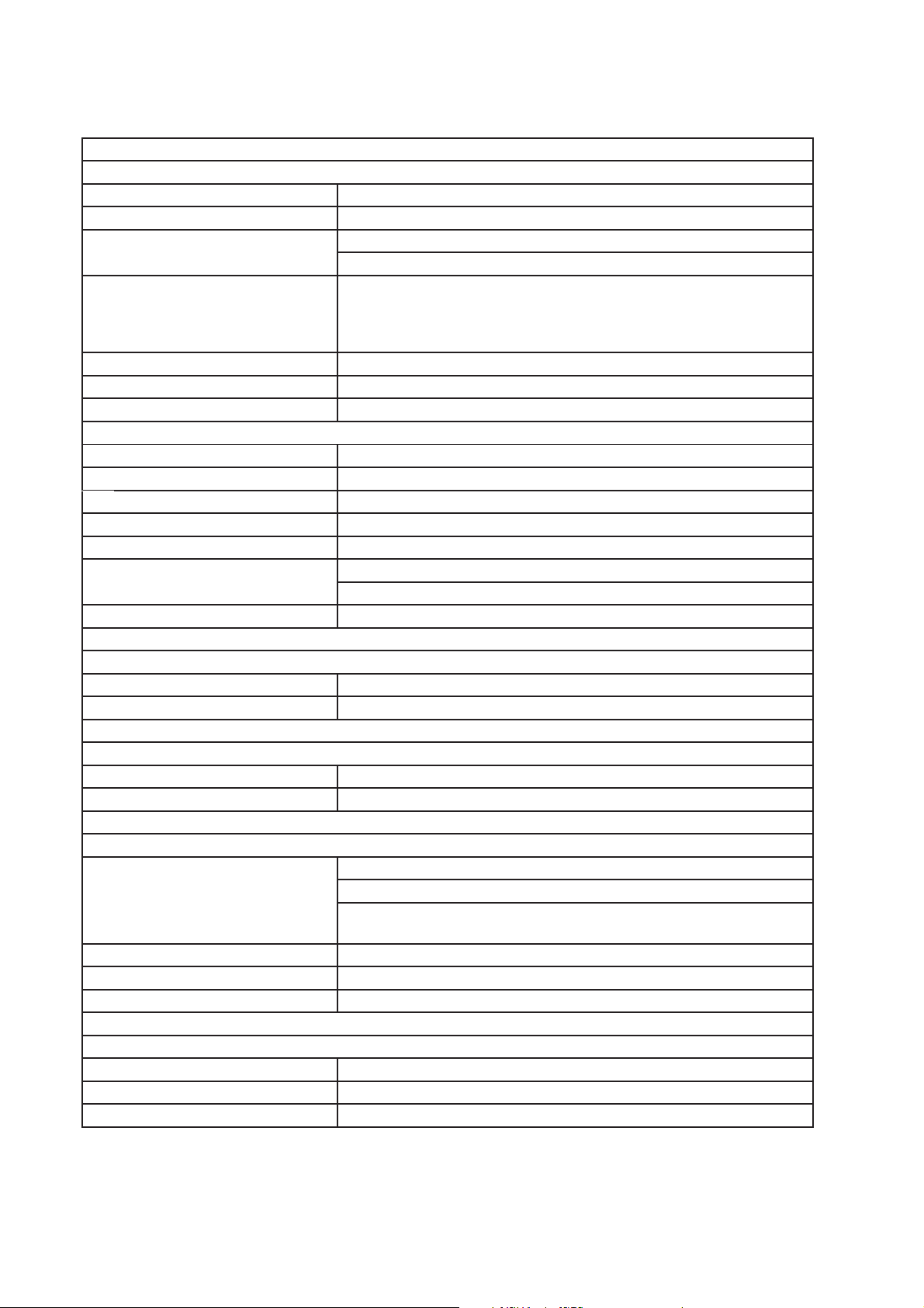
B. Performance Data
y
Pressure data is recorded at 5 min. into freezing cycle. The data not in bold
should be used for reference only.
1. IM-500SAA
APPROXIMATE ICE
PRODUCTION PER 24 HR.
lbs./day kg./da
APPROXIMATE ELECTRIC
CONSUMPTION
watts 100/38
APPROXIMATE WATER
CONSUMPTION PER 24 HR.
gal./day m3/day
FREEZING CYCLE TIME
min. 100/38
HARVEST CYCLE TIME
min. 100/38
HEAD PRESSURE
PSIG kg/cm2G
SUCTION PRESSURE
PSIG kg/cm2G
AMBIENT TEMP.
(ºF/ºC)
70/21 500 227 481 218 447 203
80/27 485 220 456 207 417 189
90/32 481 218 435 197 397 180
100/38 471 214 426 193 363 165
70/21
80/27
90/32
70/21 105 0.40
80/27 101 0.38 92 0.35 84 0.32
90/32 99 0.38 86 0.33 78 0.30
100/38 91 0.34 84 0.32 71 0.27
70/21
80/27
90/32
70/21
80/27
90/32
70/21 210 14.8
80/27 226 15.9 260 18.2 281 19.7
90/32 231 16.3 283 19.9 306 21.5
100/38 234 16.5 288 20.3 327 23.0
70/21 42 3.0 45 3.1 48 3.4
80/27 44 3.1 48 3.4 52 3.6
90/32 45 3.1 51 3.6 55 3.8
100/38 45 3.2 52 3.6 58 4.1
WATER TEMP. (ºF/ºC)
50/10 70/21 90/32
920
936
941
945
17
18
18
19
3.6
3.2
3.0 1.5
2.4
941
968
990
996
99 0.38 92 0.35
18
20
22
23
3.0
2.2
1.6
1.6
231 16.3 255 18.0
967
993
1016
1040
20
23
24
27
2.0
2.0
1.4
TOTAL HEAT OF REJECTION FROM CONDENSER 4,500 BTU/h [AT 90ºF (32ºC) / WT 70ºF (21ºC)]
TOTAL HEAT OF REJECTION FROM COMPRESSOR 1,000 BTU/h [AT 90ºF (32ºC) / WT 70ºF (21ºC)]
38
Page 39

C. Wiring Diagram
1. IM-500SAA
39
 Loading...