

Page 1
Hoshizaki America, Inc.
Hoshizaki
Modular Crescent Cuber
Serenity Series
Model
KMS-750MLH
“A Superior Degree
of Reliability”
www.hoshizaki.com
PARTS LIST
Number: 71270
Issued: 4-19-2007
Page 2

CONTENTS
Auxiliary Codes ...................................................................................................................... 3
Note About Ordering Parts .................................................................................................... 3
Material Abbreviations ........................................................................................................... 4
A. Ice Cuber Assembly .......................................................................................................... 5
B. Refrigeration Circuit ........................................................................................................... 7
C. Water Circuit .................................................................................................................... 11
D. Control Box Assembly ..................................................................................................... 15
E. Switch Box Assembly ...................................................................................................... 17
F. Bin Switch Unit ................................................................................................................. 18
G. Label Location ................................................................................................................. 19
H. Pump Motor Assembly .................................................................................................... 20
J. Accessories and Packaging ............................................................................................. 21
2
Page 3

Auxiliary Codes
KMS-750MLH S-0 April 2007
Auxiliary Code Breakdown
K-0
Designates the year. "K" indicates the year 2000. Years progress or regress in alphabetical order.
"J" is 1999, "L" is 2001, "M" is 2002, and so on. The letters "I" and "O" were skipped.
Designates significant part changes within the same year for this model. Base is 0 and this number
advances for each change.
Example: P-1
"P" indicates 2004.
"1" indicates the first significant part change for 2004.
Note About Ordering Parts
Most assemblies cannot be ordered as complete units; parts in the assemblies generally must be ordered
separately.
3
Page 4

Material Abbreviations
ALUMINUM
AL = Aluminum
COPPER
CU = Copper
PLASTIC
ABS = Acrylonitrile -butadiene - styrene
AC = Polyacetal
EVA = Ethylene vinyl acetate
PA = Polyamide = Nylon
PC = Polycarbonate
PE = Polyethylene
PES = Polyester
PETP = Polyethylene terephthalate = Tetlon
PP = Polypropylene
PS = Polystyrene
PTFE = Polytetrafluoroethylene = Teflon
PUR = Polyurethane
PVC = Polyvinyl chloride
RUBBER
VN = Vinyl Nitrile
EPDM = EP rubber
NBR = Nitrile butadiene rubber
NR = Natural rubber
NP = Neoprene
SI.R = Silicone rubber
SY.R = Synthetic rubber
EPH = Epichlorohydrin
STEEL
GS = Galvanized steel
SS = Stainless steel
PS = Plated steel
PAS = Primed steel
4
Page 5
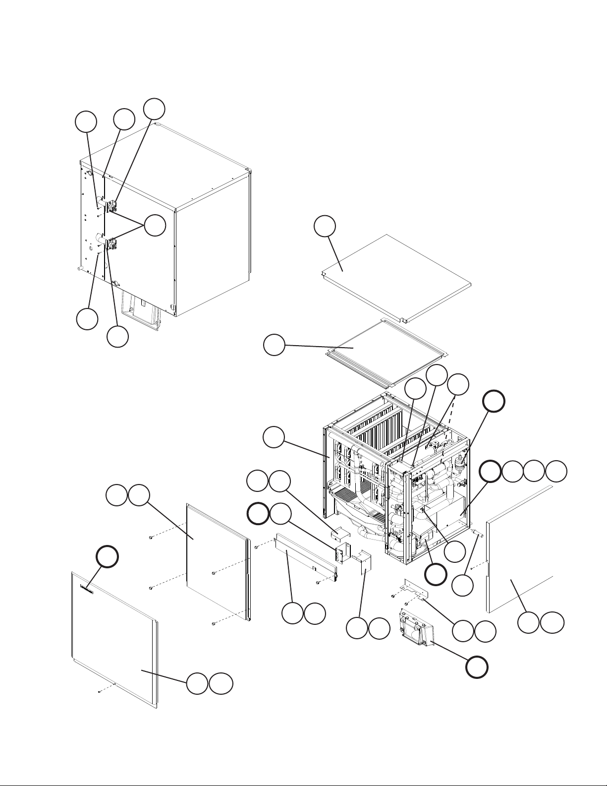
A. Ice Cuber Assembly
KMS-750MLH
S-0
2
2a
B3
3a
3
10 18
B2
16
11
14
12
B1
B
1
4a
4
D1
6a
6
D
G
17
17a
E
E1
13
C
8
9
18
5a
5
7
19
15
15a
F
5
Page 6
Title: A. Ice Cuber Assembly Model: KMS-750MLH
Required Number
Index
No. Description
B Refrigeration Circuit - 1A1359A01 1
B1 T2 Screw 4×8, SS 7P32-0408 4
Truss Head Screw 4×8, SS 7C32-0408 4
B2
B3 T2 Screw 4×8, SS 7P32-0408 6
C Water Circuit - 1A1357A01 1
D Control Box Assembly - 3A3247A01 1
D1 T2 Screw 4×8, SS 7P32-0408 4
E Switch Box Assembly - 4A3540A01 1
E1 T2 Screw 4×8, SS 7P32-0408 2
F Bin Switch Unit (bin control) - 3A3249A01 1
G Label Location - 2A4217A01 1
1 Evaporator Case - 1A0971G01 1
2 Bracket / Coupling GS 4A3891-02 1
2a T2 Screw
3 Bracket / Coupling GS 4A3891-02 1
3a T2 Screw 4×8, SS 7P32-0408 2
4 Control Box Cover GS 3A3248-01 1
4a T2 Screw 4×8, SS 7P32-0408 1
5 Switch Box - Bracket GS 3A3304-01 1
5a Truss Head Screw 4×8, SS 7C32-0408 2
6 Switch Box - Cover GS 4A3623-01 1
6a T2 Screw 4×8, SS 7P32-0408 1
7 Switch Bracket (bin control) SS 4A3541-01 1
8 Pipe (B) - Evaporator Case - 4A3525-01 1
9 Front Frame - 4A3542G01 1
10 Front Insulation - 3A3250G01 1
11 Top Insulation - 3A3251G01 1
Bushing OCB-625 428394-03 1
12
13 Wire Saddle - 4A0338-02 5
14 Wire Saddle - 4A0338-01 3
15 Side Panel (R) SS 2A3225G01 1
15a Truss Head Screw 4×8, SS 7C32-0408 1
16 Top Panel SS 2A3226-01 1
17 Front Panel SS 2A3236-01 1
17a Truss Head Screw 4×12, SS 7C32-0412 1
18 Thumbscrew ABS, SS 415949G10 6
19 Thumbscrew ABS, SS 415949G08 2
Material or
Model Number Part Number
4×8, SS 7P32-0408 2
S-0
6
Page 7
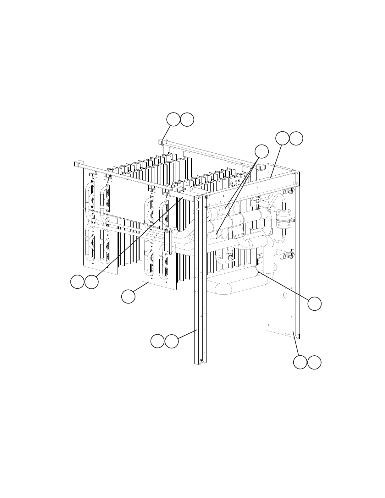
B. Refrigeration Circuit
1/2
KMS-750MLH
S-0
6a
6
2a
2
11
3a
3
5
36
1a
1
4a
4
7
Page 8

B. Refrigeration Circuit
2/2
KMS-750MLH
S-0
21
22
32
14a
14
13
9a
97
8
10
33
44
34
35
30
14b
17
23
12
24
27
25
15
28
25
29
25a
16
18
25a
26
19
16a
26
26a
16b
26a
36
42
37
40
36
43
Detailed Thermistor and TXV Bulb Attachment
41
8
38
39
20
31
Detailed Check Valve
Attachment
Page 9

Title: B. Refrigeration Circuit Model: KMS-750MLH
Required Number
Index
No. Description
1 Side Frame (A) GS 2A3230-01 1
1a Truss Head Screw 4×8, SS 7C32-0408 4
2 Side Frame (B) GS 3A3256-01 1
Truss Head Screw 4×8, SS 7C32-0408 2
2a
3 Front Frame GS 3A3257-01 1
3a Truss Head Screw 4×8, SS 7C32-0408 4
4 Rear Panel GS; See A. Ice
4a Truss Head Screw 4×8, SS 7C32-0408 1
5 Evaporator - 2A4196G01 1
6 Frame Seal EPDM 323925-01 4
6a Truss Head Screw 4×8, SS 7C32-0408 4
7 Rubber Tube (A) - 323974-01 1
8 Insulation - 436597-01 1
9 Insulation Holder SS 3A0979-01 1
9a T2 Screw 4×8, SS 7P32-0408 2
10 Expansion Valve - 4A1414-01 2
11 Expansion Valve Cover - 3A0944-01 2
Strainer - 441569-02 1
12
13 Valve Body - Hot Gas - 4A3978-01 1
14 Coil - Valve - 4A3277-01 1
14a Bolt - 4A3277F01 1
14b Truss Head Screw 4×8, SS 7C32-0408 2
15 Valve Body - Line - 4A3276-01 1
16 Coil - Valve - 4A3277-01 1
16a Bolt - 4A3277F01 1
16b Truss Head Screw 4×8, SS 7C32-0408 2
17 Bracket / Coil GS; See A. Ice
18 Drier - 4A2663-01 1
19 Nylon Tie PLWP3H-TL 8911-0301 1
Check Valve - 4A1373-01 2
20
Coupling (male) 5782-8-10 434072-01 1
21
22 Tube Holder - L (liquid line) GS; See A. Ice
Material or
Model Number Part Number
2A3231-01 1
Cuber Assembly, item B3
for additional
mounting
screws
4A3890-01 2
Cuber Assembly, item B1
for mounting
screws
438245-01 1
Cuber Assembly, item B2
for mounting
screws
S-0
9
Page 10

Title: B. Refrigeration Circuit Model: KMS-750MLH
Required Number
Index
No. Description
Coupling (male) 5782-10-11 4A3826-01 1
23
Tube Holder - L (suction line) GS; See A. Ice
24
Service Valve - 4A3420-01 2
25
Hex Head Tapping Screw 1/4×20×1/2 7B03I1412 2
25a
Bracket - Service Valve GS 4A3892-01 2
26
26a T2 Screw
Copper Tube (A) - 3A3258G01 1
27
Copper Tube (B) - 4A3555-01 1
28
Copper Tube (C) - 3A3299G01 1
29
30 Copper Tube (D) - 3A3259G01 1
31 Copper Tube (E) - 4A3556G01 1
Copper Tube (F) - 3A4421G01 1
32
33 Copper Tube (G) - 3A4422G01 1
34 Copper Tube (J) - 3A3262G01 1
35 Heat Exchanger - 3A3263G01 1
36 Cable Tie - 8911-0200 10
37 Holder - Expansion Valve - 3A0107-01 2
38 Holder Thermistor COPPER 438247-01 1
39 Insulation - Thermistor - 427441-01 1
40 Hose Clamp No. 6806 443461-02 2
41 Thermistor - 429006-05 1
Insulation Tubing L=365 7762-2943 1
42
43 Insulation Tubing L=70 7762-2943 1
44 Elbow - 4A1059-01 1
Material or
Model Number Part Number
438245-02 1
Cuber Assembly, item B2
for mounting
screws
4×8, SS 7P32-0408 4
S-0
10
Page 11

C. Water Circuit
1/2
KMS-750MLH
S-0
12
14
10
19
12
18
6
20
21
1a
1
18
50
18
13
8
48
17
11
16
15
33
17
37
52
4
25
47
2
3
51
2
3a
58
25a
49
4
26
26a
7
15
9
3a
3
40
35
5
16
38
39
18
11
To pump
Page 12

C. Water Circuit
2/2
KMS-750MLH
S-0
46
56
56a
56b
63
28
45
56
43
56a
54
56b
55
63
42
32
29
61
61a
25
65
25a
53
27
64
60
15
27a
41
44
12
62
59
57
16
23
59a
57a
36
34
22
To Discharge
Hose (A)
30
31
24
23
22a
H
H1
Page 13

Title: C. Water Circuit Model: KMS-750MLH
Required Number
Index
No. Description
H Pump Motor Assembly HS-0205 2A3237A02 1
H1 Truss Head Screw 5×8, SS 7C32-0508 2
1 Water Supply Pipe - 3A3273G01 1
1a T2 Screw 4×8, SS 7P32-0408 2
2 Rubber Gasket - 413854-03 2
3 Water Valve Bracket GS 3A3274-01 2
3a Truss Head Screw 4×8, SS 7C32-0408 2
4 Water Valve (harvest & fill) J248-032 3U0111-02 2
5 Vinyl Hose L=40 7716-1216 1
6 Distributor (A) - 4A3528-01 1
7 Distributor (B) - 3A3239-01 1
8 Distributor (C) - 4A3530-01 1
9 Flange - 439267-02 1
10 Distributor Hose (A) - 3A4409-01 1
11 Distributor Hose (B) - 3A4409-02 1
Distributor Hose (C) - 3A4410-01 2
12
13 Joint Pipe - 439297-02 1
14 Hose Clamp 13.5 mm, SS 427443-07 4
15 Hose Clamp 18 mm, SS 427443-05 5
16 Hose Clamp 20 mm, SS 427443-06 6
17 Hose Clamp 25 mm, SS 427443-03 3
18 Hose Clamp 32 mm, SS 427443-09 8
19 Spray Tube - 437049G04 4
Spray Guide (A) 5 cups 208586-01 8
20
Spray Guide (D) 3 cups 208586-04 4
21
22 Pump - Drain Pan SS 3A3275G01 1
Truss Head Screw 4×8, SS 7C32-0408 2
22a
Vinyl Hose L=50 7716-1519 2
23
Drain Pipe SS 4A3568G01 1
24
Water Valve (wash & drain) - 4A3722-01 2
25
Truss Head Screw 4×8, SS 7C32-0408 4
25a
Drain Valve Bracket (A) GS 4A3569-01 1
26
Truss Head Screw 4×8, SS 7C32-0408 2
26a
Drain Valve Bracket (B) GS 4A3570-01 1
27
Truss Head Screw 4×8, SS 7C32-0408 2
27a
Tank - 1A1146G01 1
28
Suction Hose (A) - 3A3234-01 1
29
30 Suction Hose (B) - 4A3534-01 1
31 Insulation Tubing L=125 7762-3555 1
Pipe (A) - Evaporator Case - 4A3524-01 1
32
33 Pipe (C) - Evaporator Case - 4A3526-01 1
34 Pipe (D) - Evaporator Case - 4A3527-01 1
35 Pipe (E) - Evaporator Case - 4A3765-01 1
36 Insulation Tubing L=60 7762-2040 1
Material or
Model Number Part Number
S-0
13
Page 14

Title: C. Water Circuit Model: KMS-750MLH
Required Number
Index
No. Description
37 Vinyl Hose L=320 7716-1519 1
38 Hose - Inlet - 3A3496-01 1
39 Insulation Tubing L=200 7762-2030 1
40 Hose - Outlet - 3A3497-01 1
41 Vinyl Hose L=45 7716-1519 1
Drain Hose (to overflow cap) - 4A3536-01 1
42
43 Overflow Cap - 2A3215-01 1
44 Vinyl Hose L=80 7716-1216 1
45 Cube Guide - 1A0966-01 2
46 Separator - Tank - 2A3220-01 1
47 Discharge Hose (A) - 4A3532-01 1
48 Discharge Hose (B) - 4A3533-01 1
49 Insulation Tubing L=230 7762-3555 1
50 Vinyl Hose L=124 7716-2732 1
51 Inlet Hose - 4A3535-01 1
Flange - 4A3573-01 1
52
53 Drain Hose - 4A3537-01 1
54 PVC Pipe - 433509-03 1
55 Drain Hose - 434808-01 1
56 Side Seperator - 3A3235-01 2
56a Collar ABS 435269-01 4
56b Flat Head T2 Screw 4×12, SS 7P22-0412 4
57 Motor Cover GS 4A3586-01 1
57a Truss Head Screw 4×8, SS 7C32-0408 2
58 Cable Tie - 8911-0200 1
59 Float Switch - 468264-01 1
59a Truss Head Screw 4×8, SS 7C32-0408 2
60 Connector - Float Switch - 3A4169-01 1
61 Pipe Stopper GS 4A3767-01 1
61a T2 Screw 4×8, SS 7P32-0408 1
Hose - Float - 4A3766-01 1
62
63 Thumbscrew - 415949G10 2
64 Hose Clamp 27 mm, SS 427443-08 1
65 Pipe (F) - Evaporator Case - 4A4294-01 1
Material or
Model Number Part Number
S-0
14
Page 15

D. Control Box Assembly
8
8
8
8
KMS-750MLH
S-0
13
3
2
14
9a
4a
4
9
1
6a
6
7a
7
8a
8
12
11
Title: D. Control Box Assembly Model: KMS-750MLH
Index
No. Description
1 Control Box GS 2A3234-01 1
2 Control Board - 2A3792-01 1
3 Board Support CBLS37-M 4A0336-03 4
4 Terminal Block - 4A4201-01 1
4a Pan Head Screw 4×12 SS 7C12-0412 2
5 Capacitor (pump) 10.0MFD,
5a T2 Screw 4×10 SS 7P32-0410 1
Material or
Model Number Part Number
250V
15
443192-01 1
S-0
10a
10
Required Number
5a
5
15
Page 16

Title: D. Control Box Assembly Model: KMS-750MLH
Required Number
Index
No. Description
6 Relay - X1 Harvest Water Valve LY2F AC120V 406132-07 1
6a Tapping Screw 3×8 431415-01 2
7 Relay - X2 Pump Out - Pump
Motor & Drain Water Valve
7a Tapping Screw 3×8 431415-01 2
8 Relay - X3 Drain Water Valve
Cut-out
8a Tapping Screw 3×8 431415-01 2
9 Relay - X4 Pump Out - Drain
Water Valve Cut-in
9a Tapping Screw 3×8 431415-01 2
10 Transformer - 3A0172-01 1
10a T2 Screw 4×8 SS 7P32-0408 2
11 Bushing OCB-1000 428394-05 1
Wire Saddle - 4A0338-02 1
12
13 Square Washer BRASS 433537-02 1
14 Screw - Grounding 5×8 433304-02 1
15 Wire Harness (bin control) L=90 4A2200G04 1
Material or
Model Number Part Number
LY2F AC120V 406132-07 1
LY2F AC120V 406132-07 1
LY2F AC120V 406132-07 1
S-0
16
Page 17

E. Switch Box Assembly
KMS-750MLH
S-0
2
6
3
5
4
Title: E. Switch Box Assembly Model: KMS-750MLH
Index
No. Description
1 Switch Box GS 3A3277-01 1
2 Toggle Switch (control) - 443119-01 1
3 Toggle Switch (service) - 4A0985-01 1
4 Fuse Holder HTB82I 1/4 ×
5 Fuse AGC-10
6 Bushing OCB-750 428394-01 1
Material or
Model Number Part Number
4A3449-01 1
1-1/4
4A0893-07 2
250V 10A
1
Required Number
S-0
17
Page 18

F. Bin Switch Unit
KMS-750MLH
S-0
4
5
2
5
Title: F. Bin Switch Unit Model: KMS-750MLH
Index
No. Description
1 Mount - Bin Switch - 3A3278G01 1
2 Bin Control - 464574-01 1
3 Switch Guide - 3A2643-01 1
4 Switch Cover SS 4A3580-01 1
5 Thumbscrew - Black - 415949G08 6
Material or
Model Number Part Number
1
3
Required Number
S-0
18
Page 19

G. Label Location
KMS-750MLH
S-0
12
8
6
7
1
11
15
2
14
12
3
5
13
10
Title: G. Label Location Model: KMS-750MLH
Index
No. Description
1 Emblem - 4A0560-01 1
2 Label - Penguin - HA (R) - 4A0526-01 1
3 Maintenance Label - 2A3296-01 1
4 Caution Label (K) - 439150-01 1
5 Wiring Label - 2A4197-01 1
6 Nameplate - 2A3298-02 1
7 Instruction Sheet - 2A3299-01 1
8 Instruction Label - 444575-01 1
9 Manual Label - 3A3331-01 1
10 Rating Label - 2A3300-02 1
11 Label - Fuse - 4A2817-01 1
Label - 404A - 4A0960-01 2
12
13 Caution Label - 4A4209-01 1
14 Label - Alarm - 4A3517-01 1
15 Label - Control Board - 3A3444-01 1
Material or
Model Number Part Number
4
9
Required Number
S-0
19
Page 20

H. Pump Motor Assembly
KMS-750MLH
S-0
1
3
Title: H. Pump Motor Assembly Model: KMS-750MLH
2a22b
2c
2d
2e
7
8a88b
4
6
5
Required Number
Index
No. Description
1 Pump Motor
2 Pump Flange - 215662-01 1
Hex Bolt 6×40, SS 7B02-0640 4
2a
Flat Washer M6, SS 7W22-0600 4
2b
Tooth Washer M6, SS 7R22-0600 2
2c
Split Lock Washer M6, SS 7L22-0600 4
2d
Hex Nut M6, SS 7N12-0600 4
2e
3 Pump Motor Bracket SS 3A3252-01 1
4 Mechanical Seal - 4A3820-01 1
5 Packing NSF 428547-01 1
6 Impeller ABS 428548-01 1
7 Pin - 4A0648-01 1
8 Pump Housing - 2A3214-01 1
8a Hex Bolt 4×55, SS 7B02-0455 4
8b Hex Flange Nut 4, SS 7J02-0400 4
Material or
Model Number Part Number
M91A60SP201
2U0106-01 1
20
S-0
Page 21

J. Accessories and Packaging
KMS-750MLH
S-0
1
2
2a
Title: J. Accessories and Packaging Model: KMS-750MLH
Index
No. Description
1 Instruction Manual - 91A1YC10A 1
2 Universal Brace GS 4A0363-01 1
Hex Bolt 5×12 SS 7B02-0512 1
2a
Packaging
1 Pallet - 2A3684-04 1
2 Tray Assembly - Bottom - 1A1223G04 1
3 Corner Post - 3A4040-06 3
4 Tray Assembly - Top - 1A1222G04 1
5 Carton - 2A3862-41 1
6 Plastic Support - 2A3865-09 4
7 Corner Post - 3A4040-07 1
8 Post Support - 4A4211-01 1
Material or
Model Number Part Number
2A4083A01
Required Number
S-0
21
 Loading...