

Page 1
Hoshizaki
Hoshizaki America, Inc.
Low-Profile Modular Crescent Cuber
Models
KML-631MAH
“A Superior Degree
of Reliability”
www.hoshizaki.com
KML-631MWH
KML-631MRH
PARTS LIST
Number: 71263
Issued: 5-1-2007
Revised: 9-14-2015
Page 2

CONTENTS
Auxiliary Codes ...................................................................................................................... 3
Note About Ordering Parts .................................................................................................... 3
A. Main Assembly & Refrigeration Circuit .............................................................................. 4
KML-631MAH .................................................................................................................... 4
KML-631MWH ................................................................................................................... 6
KML-631MRH .................................................................................................................... 8
B. Water Circuit .................................................................................................................... 10
C. Control Box Assembly ..................................................................................................... 12
D. Accessories & Labels ...................................................................................................... 15
2
Page 3

Auxiliary Codes
KML-631MAH S-1 May 2007 KML-631MRH S-1 May 2007
S-2 December 2007 S-2 December 2007
T-0 January 2008 T-0 February 2008
U-0 January 2009 U-0 January 2009
U-1 July 2009 U-1 July 2009
V-0 January 2010 V-0 January 2010
V-1 July 2010 V-1 July 2010
A-0 January 2011 A-1 September 2011
A-1 September 2011 B-0 January 2012
B-0 January 2012 C-0 January 2013
B-1 December 2012 C-1 July 2013
C-0 January 2012 D-0 January 2014
C-1 July 2013 D-1 October 2014
D-0 January 2014 E-0 January 2015
E-0 January 2015
KML-631MWH S-0 November 2007
T-0 February 2008
U-0 March 2009
U-1 July 2009
V-0 January 2010
V-1 July 2010
A-0 January 2011
A-1 September 2011
B-0 February 2012
C-0 January 2013
C-1 July 2013
D-0 January 2014
E-0 January 2015
Auxiliary Code Breakdown
The auxiliary code is the rst two characters in the serial number. The rst character
indicates the year. Years progress or regress in alphabetical order. The series runs from
"A" through "V" and the letters "I" and "O" are skipped. The second character indicates
signicant part changes within a year. Base is "0" and this number advances for each
change. In cases where there is a letter in parentheses, this designates the month. This is
the last character in the serial number. The series runs from "(A)" through "(M)" and the
letter "(I)" is skipped. This designation is only included when identifying a parts change
within an auxiliary code.
Note About Ordering Parts
Most assemblies cannot be ordered as complete units; parts in the assemblies generally
must be ordered separately.
3
Page 4
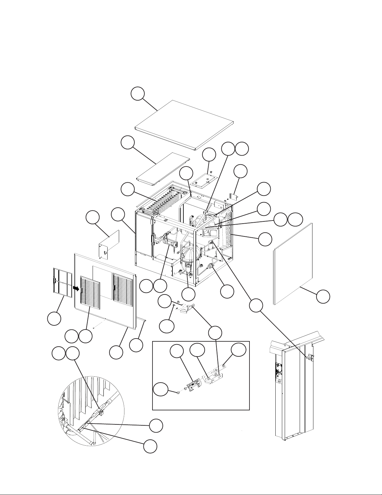
A. Main Assembly & Refrigeration Circuit
KML-631MAH
S-1 to E-0
3
6
22 23
11
10
20 21
29
17
8
30
28
7
5
27
27a
16
V-0 and Later
19
18
15
13
S-1
31
4
24
S-0 to U-1
12a
9a
9
2
1
14
12a
12
14b
26
14a
S-2 and Later
25
4
Page 5
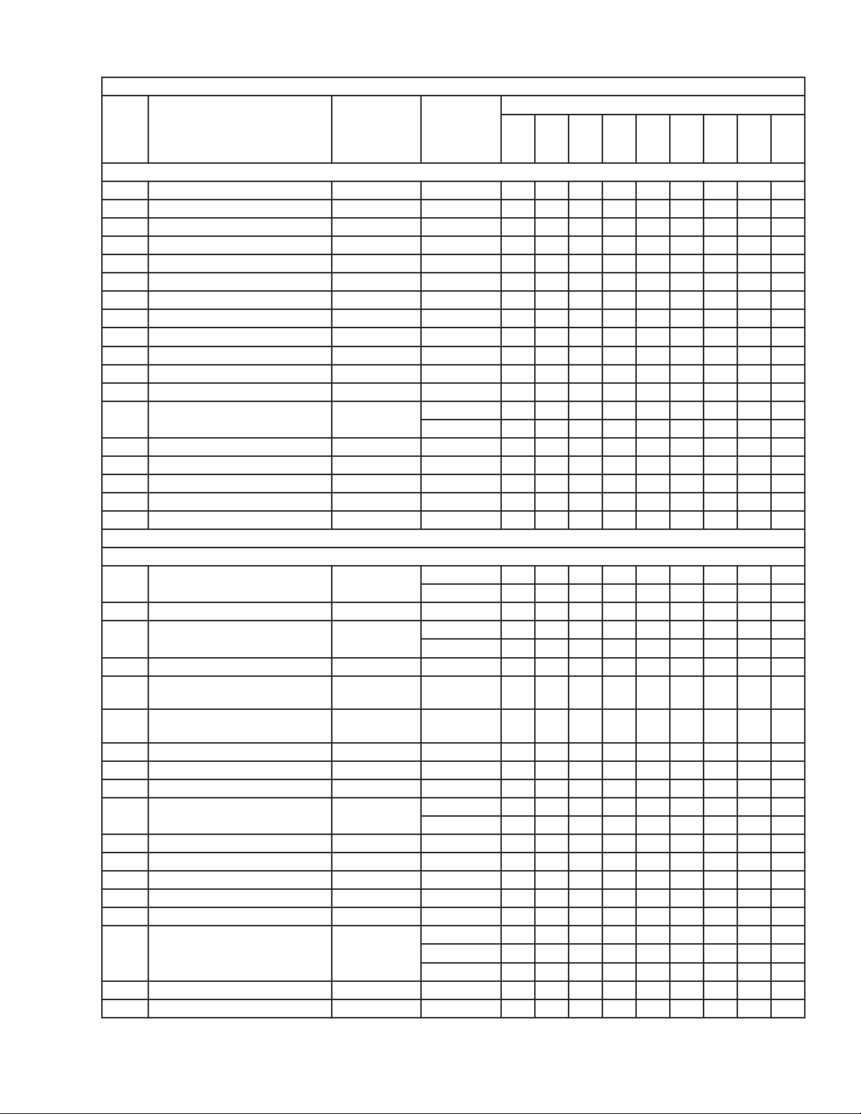
Title: A. Main Assembly & Refrigeration Circuit Model: KML-631MAH
S-2
V-0
Index
No. Description
1 Front Panel 3A4001A01 1 1 1 1
2 Gasket 4A0808L02 1 1 1 1
3 Top Panel 3A1862A01 1 1 1 1
4 Right Side Panel 2A2114G01 1 1 1 1
5 Front Insulation 2A0664G02 1 1 1 1
6 Top Insulation 215730G01 1 1 1 1
7 Control Box Cover 3A2371-01 1 1 1 1
8 Junction Box Cover 433410-01 1 1 1 1
9 Louver 1A0548-01 2 2 2 2
9a Push Retainer 4A2414-01 6 6 6 6
10 Air Filter 2A2063G01 2 2 2 2
11 Bin Control Cover 3A0664G01 1 1 1 1
12 Bin Control Thermostat
Extension Bracket
12a Thumbscrew 415949G10 2 2 2 2
13 Spacer 443545-01 2 14 Bin Control Bulb Holder 3A3903-01 1 1 1
14a Thumbscrew 415949G11 2 2 2
14b NSF Plate 4A4401G01 1 1 1
Material or
Model Number Part Number
Main Assembly
4A3436-01 1 4A4358-01 1 1 1
S-1
to
U-1
to
C-0
Required Number
C-1
to
E-0
Refrigeration Circuit
15 Compressor 4A4066-01 1 1 1 -
3A6900-01 1
16 Condenser 1A1245-01 1 1 1 1
17 Evaporator 106492G01 1 1 1 -
1A2322G01 1
18 Thermostatic Expansion Valve 4A1482-01 1 1 1 1
19 Thermostatic Expansion Valve
Cover
20 Thermostatic Expansion Valve
Bulb Holder
21 Clamp 443461-02 1 1 1 1
22 Hot Gas Valve Body 4A3978-01 1 1 1 1
23 Valve Coil 4A3277-01 1 1 1 1
24 High-Pressure Switch 433441-07 1 1 -
25 Thermistor 429006-03 1 1 1 1
26 Thermistor Holder 427430-01 1 1 1 1
27 Fan Motor 4A3158-01 1 1 1 1
27a Self-Locking Nut 7N21I0832 1 1 1 1
28 Fan Blade 4A4014-01 1 1 1 1
29 Heat Exchanger 2A3876G01 1 1 -
30 Strainer 441569-02 1 1 1 1
31 Drier 4A2666-01 1 1 1 1
3A0944-01 1 1 1 1
3A0107-01 1 1 1 1
463180-04 1 1
2A5327G01 1 1A2973G01 1
5
Page 6

A. Main Assembly & Refrigeration Circuit
KML-631MWH
S-0 to E-0
3
6
28
9
22
21
8
16
15
5
7
26
V-0 and Later
4
14
27
17 18
23
S-0 to U-1
11
13
S-0
10a
10
12b
1
10a
2
12
19 20
24
12a
T-0 and Later
25
6
Page 7

Title: A. Main Assembly & Refrigeration Circuit Model: KML-631MWH
V-0
Index
No. Description
1 Front Panel 3A4001A02 1 1 1 1
2 Gasket 4A0808L02 1 1 1 1
3 Top Panel 3A1862A01 1 1 1 1
4 Right Side Panel 2A2114G01 1 1 1 1
5 Front Insulation 2A0664G02 1 1 1 1
6 Top Insulation 215730G01 1 1 1 1
7 Control Box Cover 3A2371-01 1 1 1 1
8 Junction Box Cover 433410-01 1 1 1 1
9 Bin Control Cover 3A0664G01 1 1 1 1
10 Bin Control Thermostat
Extension Bracket
10a Thumbscrew 415949G10 2 2 2 2
11 Spacer 443545-01 2 12 Bin Control Bulb Holder 3A3903-01 1 1 1
12a Thumbscrew 415949G11 2 2 2
12b NSF Plate 4A4401G01 1 1 1
Material or
Model Number Part Number
Main Assembly
4A3436-01 1 4A4358-01 1 1 1
S-0
T- 0
U-1
to
C-0
Required Number
C-1
to
E-0
Refrigeration Circuit
13 Compressor 4A4066-01 1 1 1 -
3A6900-01 1
14 Condenser 2A2359G03 1 1 1 -
3A7323-01 1
15 Water Regulating Valve 4A0911-07 1 1 1 1
16 Evaporator 106492G01 1 1 1 -
1A2322G01 1
17 Thermostatic Expansion Valve 4A1482-01 1 1 1 1
18 Thermostatic Expansion Valve
Cover
19 Thermostatic Expansion Valve
Bulb Holder
20 Clamp 443461-02 1 1 1 1
21 Hot Gas Valve Body 4A3978-01 1 1 1 1
22 Valve Coil 4A3277-01 1 1 1 1
23 High-Pressure Switch 433441-05 1 1 -
24 Thermistor 429006-03 1 1 1 1
25 Thermistor Holder 427430-01 1 1 1 1
26 Strainer 441569-02 1 1 1 1
27 Drier 4A2666-01 1 1 1 1
28 Heat Exchanger 2A3876G01 1 1 -
3A0944-01 1 1 1 1
3A0107-01 1 1 1 1
463180-05 1 1
2A5327G01 1 1A2973G01 1
7
Page 8

A. Main Assembly & Refrigeration Cirucuit
KML-631MRH
S-1 to E-0
3
6
9
31
21
23
16
8
7
29
5
30
27
V-0 and Later
4
18
17
14
28
15
24
S-1 to U-1
13
1
2
10a
22 23
S-1
11
10
12
10a
12b
2019
12a
S-2 and Later
25
26
8
Page 9

Title: A. Main Assembly & Refrigeration Circuit Model: KML-631MRH
V-0
Index
No. Description
1 Front Panel 3A4001A02 1 1 1 1
2 Gasket 4A0808L02 1 1 1 1
3 Top Panel 3A1862A01 1 1 1 1
4 Right Side Panel 2A2114G01 1 1 1 1
5 Front Insulation 2A0664G02 1 1 1 1
6 Top Insulation 215730G01 1 1 1 1
7 Control Box Cover 3A2371-01 1 1 1 1
8 Junction Box Cover 433410-01 2 2 2 2
9 Bin Control Cover 3A0664G01 1 1 1 1
10 Bin Control Thermostat
Extension Bracket
10a Thumbscrew 415949G10 2 2 2
11 Spacer 443545-01 2 12 Bin Control Bulb Holder 3A3903-01 1 1 1
12a Thumbscrew 415949G11 2 2 2
12b NSF Plate 4A4401G01 1 1 1
Material or
Model Number Part Number
Main Assembly
4A3436-01 1 4A4358-01 1 1
S-1
S-2
U-1
to
C-0
Required Number
C-1
to
E-0
Refrigeration Circuit
13 Compressor 4A4066-01 1 1 1 -
3A6900-01 1
14 Crankcase Heater 434924-01 1 1 1 -
4A5091-01 1
15 Receiver 437652-01 1 1 1 1
16 Evaporator 106492G01 1 1 1 -
1A2322G01 1
17 Thermostatic Expansion Valve 4A1482-01 1 1 1 1
18 Thermostatic Expansion Valve
Cover
19 Thermostatic Expansion Valve
Bulb Holder
20 Clamp 443461-02 1 1 1 1
21 Hot Gas Valve Body 4A3978-01 1 1 1 1
22 Liquid Line Valve Body 4A3276-01 1 1 1 1
23 Valve Coil 4A3277-01 2 2 2 2
24 High-Pressure Switch 433441-07 1 1 -
25 Thermistor 429006-03 1 1 1 1
26 Thermistor Holder 427430-01 1 1 1 1
27 Strainer 441569-02 1 1 1 1
28 Drier 4A2666-01 1 1 1 1
29 Liquid Line Coupling 433751G01 1 1 1 1
30 Discharge Line Coupling 434136G01 1 1 1 1
31 Heat Exchanger 2A3876G02 1 1 -
3A0944-01 1 1 1 1
3A0107-01 1 1 1 1
463180-04 1 1
2A5327G02 1 1A2973G02 1
9
Page 10

B. Water Circuit
KML-631M_H
S-0 to E-0
8
10
12
9
13
11
20
3
25
18 19
24
26
7
27
23
5
28
6
16
17
22
2
15
21
14
1
4
10
Page 11

Title: B. Water Circuit Model: KML-631M_H
Required Number
U-1
A-1
Index
No. Description
1 Pump Motor 2A2861-01 1 1 -
2 Pump Motor Bracket 2A4920G01 1 1 1
3 Elbow 4A0393-01 1 1 1 1 1 1
4 Water Supply Pipe 4A0768G04 1 1 1 1 1 1
5 Rubber Gasket 413854-03 1 1 1 1 1 1
6 Inlet Water Valve 3U0111-04 1 1 1 1 1 -
7 Solenoid Valve (Drain and
Cleaning Valve)
8 Spray Tube 1A0260-02 1 1 1 1 1 1
9 Spray Guide 208586-01 6 6 6 6 6 -
10 Water Supply Tube 2A0079-01 1 1 1 1 1 1
11 Flange 439267-01 1 1 1 1 1 1
12 Plug 4A0176-01 2 2 2 2 2 2
13 Water Supply Tee 4A1006-01 1 1 1 1 1 1
14 Float Switch 4A3624-01 1 1 1 1 1 1
15 Float Switch Bracket 327757-01 1 1 1 1 1 1
16 Float Switch Cover 3A0665-01 1 1 1 1 1 1
17 Float Switch Spacer 4A0650-01 1 1 1 1 1 1
18 Drain Plug 309246-01 1 1 1 1 1 1
19 O-Ring 7611-P015 1 1 1 1 1 1
20 Cube Guide 2A0660-01 1 1 1 1 1 1
21 Vinyl Hose L=150 mm 7716-1216 1 1 1 1 1 1
22 Vinyl Hose L=415 mm 7716-1519 1 1 1 1 1 1
23 Vinyl Hose L=55 mm 7716-1519 1 1 1 1 1 1
24 Pump Hose 4A1007-01 1 1 1 -
Vinyl Hose L=245 mm 7716-2025 1 -
Hose B 325867-01 1 1
25 Connecting Pipe 3A1335-02 1 1 1 1 1 1
26 Rubber Ring 4A1004-01 1 1 1 1 1 1
27 Bypass Hose 4A1005-01 1 1 1 1 1 1
28 Joint Pipe 439329-01 1 1 1 1 1 1
Material or
Model Number Part Number
2A4408-01 1 4A4259-01 1 1 1
3U0111-03 1
439322-01 2 4A3722-01 2 2 2 2 2
2A4282-02 2
S-0
S-1 S-2
T- 0
U-0
to
A-0
to
C-0
C-1
to
E-0
Hose Clamp 25 mm 427443-03 2 2 2 2 2 2
Hose Clamp 18 mm 427443-05 9 9 9 9 9 9
Hose Clamp 27 mm 427443-08 1 1 1 1 1 1
Hose Clamp 20 mm 427443-06 1 1 1 1 1 1
11
Page 12

C. Control Box Assembly
KML-631M_H
1/2
S-0 to C-0
1
14
2
6
13
3
15
T-0 and U-0
9 10
12
7a
7
11
8
5
V-1 to D-0
KML-631MRH
S-0 to V-0
4
12
V-1 and Later
KML-631MAH
KML-631MWH
Page 13

C. Control Box Assembly
KML-631M_H
2/2
C-1 to E-0
X10 - Pump Motor Relay
X11 - Inlet Water Valve Relay
X12 - Service Relay
X13 - Crankcase Heater Relay (KML-631MRH)
1 2 3
14
12
13
X10X11X12
4
KML-631MAH
KML-631MWH
16
6
7a
7
11
5
9 10
8
1
2
14
V-1 to D-0
4
D-1 and Later
D-1 and Later
13
X10X11X12
X13
KML-631MRH
16
6
3
9 10
7a
7
11
8
5
13
Page 14

Title: C. Control Box Assembly Model: KML-631M_H
Required Number
V-1
B-1
C-1
Index
No.
Description
1 Start Capacitor 145-175MFD,
2 Run Capacitor 25MFD,
3 Start Relay 4A1107-09 1 1 1 1 1 -
4 Magnetic Contactor ALL 428393-01 1 1 1 -
Compressor Relay KML-631MAH
5 Service Switch 4A0895-01 1 1 1 1 1 1 1
6 Control Transformer 3A0172-01 1 1 1 1 1 1 1
7 Control Board "E" Board 2A1410-01 1 1 1 1 -
7a Control Board Support 4A0336-03 4 4 4 4 4 4 4
8 Control Switch 443119-01 1 1 1 1 1 1 1
9 Fuse Holder 4A5443-01 1 1 1 1 1 1 1
10 Fuse AGC-10A,
11 Bin Control Thermostat 4A2879-01 1 1 1 1 1 1 1
12 Fan Motor Capacitor KML-631MAH
13 Relay (X10, X11, X12, X13) KML-631MAH
14 Pump Motor Capacitor 2.5MFD,
15 Pump Motor Relay 120VAC 4A1307-01 1 16 Jumper Connector 4A4883G01 1 1 1 1 1 1 1
Material or
Model Number Part Number
3A0076-01 1 1 1 1 1 -
250VAC
108-130MFD,
330VAC
440VAC
KML-631MWH
KML-631MRH 4A5096-01 1 1 1 -
"G" Board 2A3792-01 1 1 1
250VAC
5.0MFD,
250VAC
KML-631MWH
KML-631MRH 1 1 1 1 1 3 4
250VAC
3A0076-22 1 1
3A2005-03 1 1 1 1 1 3A2005-10 1 1
4A1107-07 1 1
4A3140-01 1 1 1 1
4A3140-01 1
4A0893-07 1 1 1 1 1 1 1
443192-02 1 1 1 1 1 1 1
406132-07 1 1 1 1 1 3 3
4A2128-05 1 1 1 1 1
S-0
S-2
T-0
U-0
U-1
V-0
to
B-0
to
C-0
to
D-0
D-1
E-0
14
Page 15

D. Accessories & Labels
KML-631M_H
S-0 to E-0
2
4
3
Title: D. Accessories & Labels Model: KML-631M_H
S-0
to
Index
No. Description
1 Universal Brace GS 4A0363-01 2 2
1a Hex Head Bolt 5×12, SS 7B02-0512 2 2
2 Hoshizaki Emblem 4A0560-01 1 1
3 Penguin Label 4A0526-01 1 1
4 Air Filter KML-631MAH 426177-01 1 -
Material or
Model Number Part Number
D-0
(H)
Required Number
D-0
(J)
to
E-0
15
 Loading...