

Page 1

Hoshizaki
Hoshizaki America, Inc.
Modular Crescent Cuber
Models
KML-451MAH
“A Superior Degree
of Reliability”
www.hoshizaki.com
KML-451MWH
PARTS LIST
Number: 71262
Issued: 10-12-2006
Revised: 9-25-2009
Page 2

CONTENTS
Auxiliary Codes ...................................................................................................................... 3
Note About Ordering Parts .................................................................................................... 3
Material Abbreviations ........................................................................................................... 4
A. Ice Cuber Assembly .......................................................................................................... 5
KML-451MAH .................................................................................................................... 5
KML-451MWH ................................................................................................................... 8
B. Refrigeration Circuit ......................................................................................................... 10
KML-451MAH .................................................................................................................. 10
KML-451MWH ................................................................................................................. 14
C. Water Circuit .................................................................................................................... 18
D. Control Box Assembly ...................................................................................................... 22
E. Label Location ................................................................................................................. 24
KML-451MAH .................................................................................................................. 24
KML-451MWH ................................................................................................................. 26
F. Top Panel Assembly ......................................................................................................... 28
G. Front Panel Assembly ..................................................................................................... 29
H. Accessories & Packaging ................................................................................................ 30
2
Page 3

Auxiliary Codes
KML-451MAH R-0 June 2006
S-1 January 2007
S-2 December 2007
T-0 January 2008
T-1 November 2008
T-2 December 2008
U-0 January 2009
U-1 August 2009
KML-451MWH R-0 June 2006
S-1 April 2007
S-2 December 2007
T-0 January 2008
U-0 January 2009
U-1 January 2009
Auxiliary Code Breakdown
The auxiliary code is the rst two characters in the serial number. The rst character
indicates the year. Years progress or regress in alphabetical order. The series runs from
"A" through "V" and the letters "I" and "O" are skipped. The second character indicates
signicant part changes within a year. Base is "0" and this number advances for each
change. In cases where there is a letter in parentheses, this designates the month. This
is the last character in the serial number. The series runs from "(A)" through "(M)" and the
letter "(I)" is skipped. This designation is only included when identifying a parts change
within an auxiliary code.
Note About Ordering Parts
Most assemblies cannot be ordered as complete units; parts in the assemblies generally
must be ordered separately.
3
Page 4

Material Abbreviations
ALUMINUM
AL = Aluminum
COPPER
CU = Copper
PLASTIC
ABS = Acrylonitrile -butadiene -styrene
AC = Polyacetal
EVA = Ethylene vinyl acetate
PA = Polyamide = Nylon
PC = Polycarbonate
PE = Polyethylene
PES = Polyester
PETP = Polyethylene terephthalate = Tetlon
PP = Polypropylene
PS = Polystyrene
PTFE = Polytetrauoroethylene = Teon
PUR = Polyurethane
PVC = Polyvinyl chloride
RUBBER
VN = Vinyl Nitrile
EPDM = EP rubber
NBR = Nitrile butadiene rubber
NR = Natural rubber
NP = Neoprene
SI.R = Silicone rubber
SY.R = Synthetic rubber
EPH = Epichlorohydrin
STEEL
GS = Galvanized steel
SS = Stainless steel
PS = Plated steel
PAS = Primed steel
4
Page 5
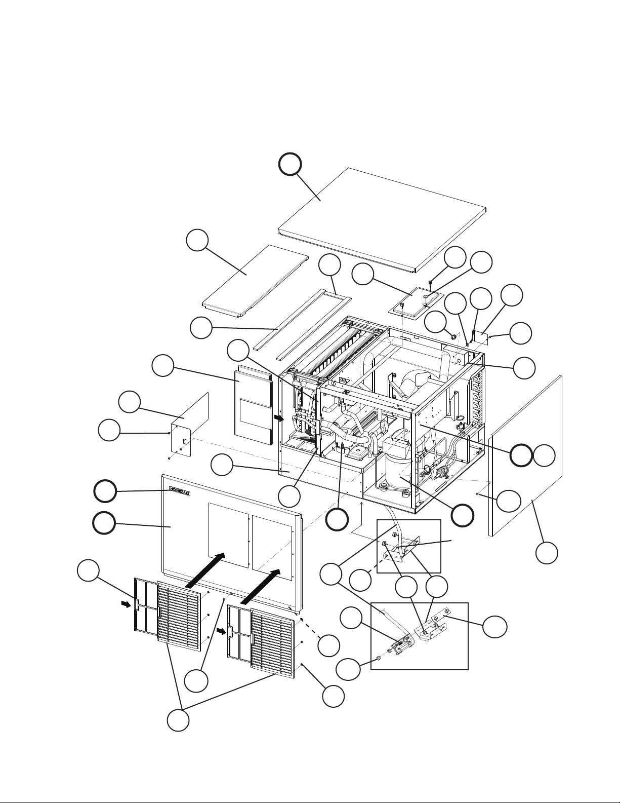
A. Ice Cuber Assembly
KML-451MAH
R-0 to U-1
11
F
19
9a
10
9
16
E
G
2a
4
3
R-0, S-1
6a
17
B
For Thermostat, see
"D. Control Box
Assembly"
6
18
23
12
2
1
24
C
21
7
5
13a
5a
D
8
D1
13
14
22
22b
20
S-2 and later
22a
G1
15
5
Page 6
Title: A. Ice Cuber Assembly Model: KML-451MAH
S-2
T- 0
Index
No. Description
B Refrigeration Circuit - 1A1143A01 1 1 -
C Water Circuit - 1A1186A01 1 1 -
D Control Box Assembly - 2A2541A01 1 1 -
D1 T2 Screw 4×8 7P31-0408 3 3 3 3
E Label Location - 3A3915A01 1 1 -
F Top Panel Assembly - 3A1862A01 1 1 1 1
G Front Panel Assembly - 3A1859A01 1 1 1 1
G1 Truss Head Screw 4×8, SS 7C32-0408 1 1 1 1
1 Evaporator Case HS-1014 2A2113G02 1 1 1 1
2 Control Box Cover GS 3A2371-01 1 1 1 1
2a T2 Screw 4×8 7P31-0408 3 3 3 3
3 Square Washer Brass 433537-02 1 1 1 1
4 Screw-Grounding Brass 433304-02 1 1 1 1
5 Junction Box Cover GS 433410-01 1 1 1 1
5a T2 Screw 4×8 7P31-0408 1 1 1 1
6 Thermostat Extension Bracket SS 4A3436-01 1 -
6a Thumbscrew SS, ABS 415949G10 2 2 2 2
7 Spacer PE 443545-01 2 -
8 Wire Saddle VWS4238-C 4A0338-02 2 2 2 2
9 Bin Control Cover GS 3A0664G01 1 1 1 1
9a Thumbscrew SS, ABS 415949G08 2 2 2 2
10 Capillary Ring EP Rubber 425307-01 1 1 1 1
11 Top Insulation PP 215730G01 1 1 1 1
12 Front Insulation - 2A0664G01 1 1 -
13 Side Panel (R) SS 2A2111G01 1 1 1 1
13a T2 Screw 4×8, SS 7P32-0408 1 1 1 1
14 Louver ABS 1A0548-01 2 2 2 2
15 Push Retainer - 4A2414-01 6 6 6 6
16 Air Filter ABS 2A2063G01 2 2 2 2
17 Bushing SR-30-1 420472-03 1 1 1 1
18 Gasket L=655 4A0808L02 2 2 2 2
19 Gasket L=190 4A0808L02 1 1 1 1
20 Gasket L=762 4A0808L02 1 1 1 1
21 Silicone Hose L=310 7730I3812 1 1 1 1
Material Or
Model Number Part Number
1A1678A01 1 1
1A1186A02 1 1A1186A04 1
2A4901A01 1 2A4901A03 1
3A5154A01 1 3A5480A01 1
4A4358-01 1 1 1
2A4540A01 1 1
R-0
T- 2
S-1
U-0 T- 1 U-1
Required Number
6
Page 7
Title: A. Ice Cuber Assembly Model: KML-451MAH
S-2
T- 0
Index
No. Description
22 Bulb Holder - 3A3903-01 1 1 1
22a Thumbscrew - 415949G11 2 2 2
22b NSF Plate - 4A4401G01 1 1 1
23 Gasket L=170 4A0808L02 1 1
24 Gasket L=112 4A0808L02 1 1
Material Or
Model Number Part Number
R-0
T- 2
S-1
U-0 T- 1 U-1
Required Number
7
Page 8
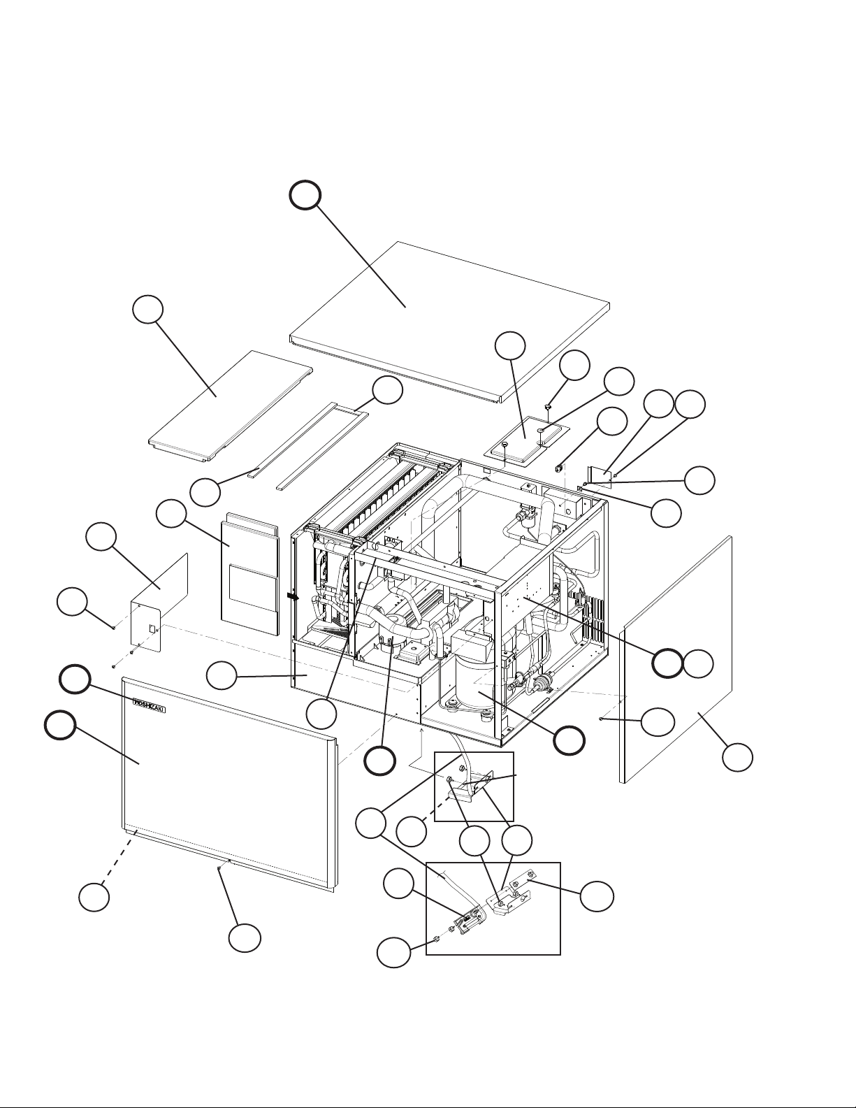
A. Ice Cuber Assembly
KML-451MWH
R-0 to U-1
11
F
16
9
9a
10
5a
5
14
G
2a
E
17
3
D
4
D1
15
12
2
1
8
13a
B
18
C
19
R-0, S-1
For Thermostat, see
"D. Control Box
Assembly"
7
6a
6
19b
13
G1
19a
S-2 and later
8
Page 9
Title: A. Ice Cuber Assembly Model: KML-451MWH
S-2
Index
No. Description
B Refrigeration Circuit - 1A1144A01 1 1 -
C Water Circuit - 1A1186A01 1 1 -
D Control Box Assembly - 2A2541A02 1 1 -
D1 T2 Screw 4×8 7P31-0408 3 3 3 3
E Label Location - 3A3916A01 1 1 -
F Top Panel Assembly - 3A1862A01 1 1 1 1
G Front Panel Assembly - 3A1859A02 1 1 1 1
G1 Truss Head Screw 4×8, SS 7C32-0408 1 1 1 1
1 Evaporator Case - 2A2113G02 1 1 1 1
2 Control Box Cover GS 3A2371-01 1 1 1 1
2a T2 Screw 4×8 7P31-0408 3 3 3 3
3 Square Washer BRASS 433537-02 1 1 1 1
4 Screw-Grounding BRASS 433304-02 1 1 1 1
5 Junction Box Cover GS 433410-01 1 1 1 1
5a T2 Screw 4×8 7P31-0408 1 1 1 1
6 Thermostat Extension Bracket SS 4A3436-01 1 -
6a Thumbscrew SS, ABS 415949G10 2 2 2 2
7 Spacer PE 443545-01 2 8 Wire Saddle VWS4238-C 4A0338-02 2 2 2 2
9 Bin Control Cover GS 3A0664G01 1 1 1 1
9a Thumbscrew SS, ABS 415949G08 2 2 2 2
10 Capillary Ring EP RUBBER 425307-01 1 1 1 1
11 Top Insulation PP 215730G01 1 1 1 1
12 Front Insulation PP 2A0664G01 1 1 1 1
13 Side Panel (R) SS 2A2111G01 1 1 1 1
13a T2 Screw 4×8, SS 7P32-0408 1 1 1 1
14 Bushing SR-30-1 420472-03 1 1 1 1
15 Gasket L=655 4A0808L02 2 2 2 2
16 Gasket L=190 4A0808L02 1 1 1 1
17 Gasket L=762 4A0808L02 1 1 1 1
18 Silicone Hose L=310 7730I3812 1 1 1 1
19 Bulb Holder - 3A3903-01 1 1 1
19a Thumbscrew SS, ABS 415949G11 2 2 2
19b NSF Plate - 4A4401G01 1 1 1
Material or
Model Number Part Number
1A1679A01 1 1
1A1186A02 1 1A1186A04 1
2A4901A02 1 2A4901A04 1
3A5155A01 1 3A5483A01 1
4A4358-01 1 1 1
R-0
S-1
to
U-0
U-1
(A-G)
Required Number
U-1
(H-M)
9
Page 10

B. Refrigeration Circuit
KML-451MAH
R-0 to T-0, T-2, U-0
33
26
11
11a
4a
4
12
2a
2
15
45
16
17
44
32
EXPANSION VALVE BULB DETAIL
6
7
8
5
5a
5b
19
34
9
19a
5c
27
26
31
20
24
21
13
21a
3a
3
1a
1
28
29
30
14
41
36
38
21b
THERMISTOR DETAIL
37
35
39
40
43
43a
40a
18
41
25
25a
10
42
42a
41
46
22
41
10
23
10a
23a
46
Page 11

B. Refrigeration Circuit
KML-451MAH
T-1, U-1
34
32
16
17
15
44
33
11
11a
4a
4
12
2a
2
3a
3
28
22
1a
1
29
EXPANSION VALVE BULB DETAIL
5
5a
5b
6
7
19a
19
43a
43
5c
26
27
13
30
24
14
41
36
35
8
20
21
21a
21b
38
THERMISTOR DETAIL
37
10
10a
39
40
40a
18
41
25
25a
11
42
42a
41
46
Page 12

Title: B. Refrigeration Circuit Model: KML-451MAH
R-0
to
T- 0
Index
No. Description
Material or
Model Number Part Number
T- 2
U-0
1 Condenser Support GS 3A3870-01 1 1
1a T2 Screw 4×8 7P31-0408 5 5
2 Condenser S-0799 2A0640-01 1 1
2a T2 Screw 4×8 7P31-0408 3 3
3 Barrier GS 4A0932-01 1 1
3a T2 Screw 4×8 7P31-0408 2 2
4 Shroud GS 3A0597G02 1 1
4a T2 Screw 4×8 7P31-0408 7 5
5 Compressor RS43C2E-
4A2300-01 1 -
CAA-219
RST45C1E-
4A4479-01 1
CAA-202
5a Spacer - 434404-01 4 -
4A2595-01 4
5b Grommet - 434403-01 4 -
4A2593-01 4
5c Bolt 8×45 437889-01 4 4
6 Terminal Cover - 4A2300F01 1 -
4A4479F01 1
7 Spring Clip - 4A2300F02 1 -
4A4479F02 1
8 Protector - 4A1805-01 1 -
4A4481-01 1
9 Protector Holder - 437339-01 1 -
10 Fan Motor Bracket GS 3A3967-01 1 1
10a Hex Head Bolt w/Washer (LF) 5×12 7B0130512 4 4
11 Fan Motor 5KCP84
4A3158-01 1 1
DFK148S
11a Self Locking Nut NO. 8-32 7N21I0832 4 4
12 Fan Blade AD10CW40 4A4014-01 1 1
13 Drier C-03E126 4A2666-01 1 1
14 Nylon Tie PLWP3H-TL 8911-0301 1 1
15 Expansion Valve
HFE-10NHDU-4
HFE-10NHDU-3
4A4008-01 1 -
4A1684-01 1
16 Holder/Expansion Valve-3/8 SS 3A0107-01 1 1
17 Clamp SS 443461-02 1 1
18 Expansion Valve Cover PE FOAM 3A0944-01 1 1
19 Evaporator Assembly - 2A0717G01 1 1
19a T2 Screw 4×16 7P31-0416 4 4
20 Valve Body-Hot Gas
21 Coil-Valve
ATS-B7SHDU-2
AMS-C12HDU-3
4A3978-01 1 1
4A3277-01 1 1
21a Bolt - 4A3277F01 1 1
21b Truss Head Screw 4×8 7C31-0408 2 2
22 Pressure Switch ACB-1UB09 433441-07 1 -
ACB-1UB44 463180-04 1
Required Number
T- 1
U-1
12
Page 13

Title: B. Refrigeration Circuit Model: KML-451MAH
R-0
to
T- 0
Index
No. Description
23 Pressure Switch Bracket GS 434938-01 1 -
23a T2 Screw 4×8 7P31-0408 1 -
24 Strainer - 4A0397-01 1 -
25 Bracket GS 4A1406-01 1 1
25a T2 Screw 4×8 7P31-0408 2 2
26 Access Valve TCJ-
27 Copper Tube (A)-High Side Copper 3A3789G01 1 -
28 Copper Tube (C)-High Side Copper 3A3790G01 1 -
Copper Tube (B)-High Side 3A5164-01 1
29 Copper Tube (D)-High Side Copper 3A3788G01 1 1
30 Copper Tube (E)-High Side Copper 3A3783-01 1 -
31 Copper Tube (A)-Hot Gas Copper 4A1878-01 1 32 Copper Tube (B)-Hot Gas Copper 2A3691G01 1 1
33 Copper Tube (A)-Access
Val ve
Copper Tube-Access Valve 3A4783G01 1
34 Heat Exchanger Copper 2A3685G01 1 -
35 Thermistor - 429006-03 1 1
36 Holder-Thermistor Copper 427430-01 1 1
37 Insulation-Thermistor (A) PE FOAM 439368-01 1 1
38 Insulation-Thermistor (B) PE FOAM 439368-02 1 1
39 Insulated Rubber Tube EPDM 4A1008G01 1 1
40 Insulation Holder SS 3A1084-01 1 -
40a T2 Screw 4×8 7P31-0408 2 2
41 Cable Tie PLT2S-M 8911-0200 12 14
42 Frame (A) GS 2A0645-01 1 1
42a T2 Screw 4×8 7P31-0408 4 4
43 Frame (B) GS 3A0595-01 1 1
43a T2 Screw 4×8 7P31-0408 4 4
44 Elbow COPPER 4A1059-01 1 1
45 Elbow COPPER 417395-03 1 46 Insulation Tube L=30 7762-1020 3 3
Material or
Model Number Part Number
441569-02 1
457729-01 2 2
2F20NHDU-1
2A4919G01 1
4A4693-01 1
Copper 3A3974G01 1 -
2A4894G01 1
4A3902-01 1
T- 2
U-0
Required Number
T- 1
U-1
13
Page 14

B. Refrigeration Circuit
KML-451MWH
R-0 to U-0
21
42 46
33
6a
6
22a
23
42
4622
1a
1
10
35
29
34
46
1211
EXPANSION VALVE BULB DETAIL
3
2
3a
2a
30
4
2b
5
2c
24
15
21
16
27
16a
8
16b
20
9
25
39
26
28
32
31a
31
7a
7
46
37
36
40
41
45
41a
14
45a
13
14a
46
44
44a
17
17a
THERMISTOR DETAIL
38
18
42
46
46
42
19
19a
43
14
Page 15

B. Refrigeration Circuit
KML-451MWH
U-1
33
22a
22
6a
6
23
1
1a
32
10
35
1211
29
46
21
EXPANSION VALVE BULB DETAIL
2a
2
2b
3a
3
4
2c
5
30
15
16
27
16a
8
16b
20
9
39
26
24
25
18
31a
31
7a
7
37
46
36
40
41
45
41a
14
45a
14a
13
46
44
44a
17
17a
THERMISTOR DETAIL
38
42
46
43
15
Page 16

Title: B. Refrigeration Circuit Model: KML-451MWH
R-0
Index
No. Description
Material or
Model Number Part Number
to
U-0 U-1
1 Rear Panel (B) GS 3A0630G03 1 1
1a T2 Screw 4×8 7P31-0408 9 9
2 Compressor RS43C2E-
4A2300-01 1 -
CAA-219
RST55C1E-
4A4376-01 1
CAA-202
2a Spacer - 434404-01 4 -
4A2595-01 4
2b Grommet - 434403-01 4 -
4A2593-01 4
2c Bolt 8×45 437889-01 4 4
3 Terminal Cover - 4A2300F01 1 -
4A4376F01 1
3a Spring Clip - 4A2300F02 1 -
4A4376F02 1
4 Protector - 4A1805-01 1 -
4A2634-02 1
5 Protector Holder - 437339-01 1 6 Condenser HS-0160 2A2359G01 1 1
6a Hex Head Bolt w/Washer (LF) 5×12 7B0130512 2 2
7 Condenser Support GS 2A2367-01 1 1
7a T2 Screw 4×8 7P31-0408 4 4
8 Drier C-03E126 4A2666-01 1 1
9 Nylon Tie PLWP3H-TL 8911-0301 1 1
10 Expansion Valve
HFE-10NHDU-4
HFE-10NHDU-3
4A4008-01 1 -
4A1684-01 1
11 Holder/Expansion Valve 3/8 SS 3A0107-01 1 1
12 Clamp SS 443461-02 1 1
13 Expansion Valve Cover PE FOAM 3A0944-01 1 1
14 Evaporator Assembly - 2A0717G01 1 1
14a T2 Screw SS, 4×16 7P32-0416 4 4
15 Valve Body-Hot Gas ATS-
4A3978-01 1 1
B7SHDU-2
16 Coil-Valve AMS-
4A3277-01 1 1
C12HDU-3
16a Bolt - 4A3277F01 1 1
16b Truss Head Screw 4×8 7C31-0408 2 2
17 Bracket GS 4A1406-01 1 1
17a T2 Screw 4×8 7P31-0408 2 2
18 Pressure Switch ACB-2UB04 433441-05 1 -
ACB-1UB43 463180-05 1
19 Pressure Switch Bracket GS 434938-01 1 -
19a T2 Screw 4×8 7P31-0408 1 -
20 Strainer - 4A0397-01 1 -
441569-02 1
21 Access Valve - 457729-01 2 2
22 Water Regulator V46DA-6 4A0911-06 1 1
22a Truss Head Screw 4×6 7C31-0406 2 2
Required Number
16
Page 17

Title: B. Refrigeration Circuit Model: KML-451MWH
R-0
Index
No. Description
23 Male Connector BRASS 4A1087-01 1 1
24 Copper Tube (A)-High Side Copper 3A3789G01 1 -
25 Copper Tube (B)-High Side Copper 3A3812G01 1 -
26 Copper Tube (C)-High Side Copper 3A3813G01 1 1
27 Copper Tube (E)-High Side Copper 3A3783-01 1 -
28 Copper Tube (A)-Hot Gas Copper 4A1878-01 1 29 Copper Tube (B)-Hot Gas Copper 2A3691G01 1 1
30 Copper Tube (A)-Access
Val ve
Copper Tube-Access Valve 3A4783G01 1
31 Copper Tube (A) Copper 3A2174G01 1 1
31a T2 Screw 4×8 7P31-0408 2 2
32 Copper Tube (B) Copper 3A2149G01 1 1
33 Heat Exchanger Copper 2A3685G01 1 -
34 Elbow Copper 417395-03 1 35 Elbow Copper 4A1059-01 1 1
36 Thermistor - 429006-03 1 1
37 Holder-Thermistor Copper 427430-01 1 1
38 Insulation-Thermistor (A) PE Foam 439368-01 1 1
39 Insulation-Thermistor (B) PE Foam 439368-02 1 1
40 Insulated Rubber Tube EPDM 4A1008G01 1 1
41 Insulation Holder SS 3A1084-01 1 -
41a T2 Screw 4×8 SS 7P32-0408 2 2
42 Insulation Tube L=30 7762-1020 4 4
43 Insulation Tube L=800 7762-1323 1 1
44 Frame (A) GS 2A0645-01 1 1
44a T2 Screw 4×8 7P31-0408 4 4
45 Frame (B) GS 3A0595-01 1 1
45a T2 Screw 4×8 7P31-0408 4 4
46 Cable Tie PLT2S-M 8911-0200 13 15
Material or
Model Number Part Number
2A4919G01 1
3A5165-01 1
4A4693-01 1
Copper 3A3974G01 1 -
2A4894G01 1
4A3902-01 1
to
U-0 U-1
Required Number
17
Page 18

C. Water Circuit
KML-451MAH, KML-451MWH
R-0 to U-1 (A-G)
5
7
8
31
32
22a
22
6
40
21
21a
9
10
11
14
17
13
15
24
14
19
24a
12
19
18
40
38
19
41
33
19
19
37
30
29
36
1a
1
20a
20
4
2
3a
3
27a
27
44
26a
26
28
25a
25
42
43
16
23
39
23a
34
34a
35
23b
18
Page 19

C. Water Circuit
KML-451MAH, KML-451MWH
U-1 (H & later)
5
7
8
31
32
22a
22
6
21a
40
21
9
10
11
14
17
13
15
19
14
12
19
45
18
45a
40
38
19
41
33
19
37
29
30
19
36
1a
1
20a
20
4
2
3a
3
27a
27
44
26a
26
28
42
43
16
23
14
23a
34
34a
35
19
25
25a
Page 20

Title: C. Water Circuit Model: KML-451MAH, KML-451MWH
Required Number
Index
No. Description
Material or
Model Number Part Number
R-0
S-2
S-1
T- 0 T- 1 U-0
U-1
(A-G)
1 Water Supply Pipe COPPER 4A0768G04 1 1 1 1 1 1
1a T2 Screw 4×8 7P31-0408 2 2 2 2 2 2
2 Rubber Gasket NR 413854-03 1 1 1 1 1 1
3 Water Valve Bracket GS 321443-01 1 1 1 1 1 1
3a T2 Screw 4×8 7P31-0408 1 1 1 1 1 1
4 Water Valve J248-647 3U0150-01 1 1 1 1 1 1
5 Spray Tube PE 1A0260-02 1 1 1 1 1 1
6 Spray Guide PE 208586-01 6 6 6 6 6 6
7 Water Supply Tube PE 2A0079-01 1 1 1 1 1 1
8 Plug - 4A0176-01 2 2 2 2 2 2
9 Water Supply Tee
SANTOPRENE
4A1006-01 1 1 1 1 1 1
10 Flange EPDM 439267-01 1 1 1 1 1 1
11 Insulation (E) PE FOAM 4A0392-01 1 1 1 1 1 1
12 Elbow
SANTOPRENE
4A0393-01 1 1 1 1 1 1
13 Connecting Pipe PE 3A1335-01 1 1 1 1 1 1
14 Hose Clamp SS, 25 mm 427443-03 3 3 3 3 3 4
15 Cube Guide ABS 2A0660-01 1 1 1 1 1 1
16 Pump Hose EPDM 4A1007-01 1 1 1 1 1 -
Vinyl Hose L=245 7716-2025 1
17 Rubber Ring EPDM 4A1004-01 1 1 1 1 1 1
18 Bypass Hose
SANTOPRENE
4A1005-01 1 1 1 1 1 1
19 Hose Clamp SS, 18 mm 427443-05 5 5 5 5 5 5
20 Solenoid Valve
207CB-GS1873
DSVP12N-2LSX120A-L1SR
439322-01 2 -
4A3722-01 2 2 2 2 2
20a Truss Head Screw 4×8 7C31-0408 4 4 4 4 4 4
21 Solenoid Valve Bracket - 4A3137-01 1 1 1 1 1 1
21a T2 Screw 4×8 7P31-0408 2 2 2 2 2 2
22 Solenoid Cover GS 4A0996-01 1 1 1 1 1 1
22a T2 Screw 4×8 7P31-0408 2 2 2 2 2 2
23 Pump Motor
OSP-B15BEJ16
PV-211BHZ1
2A2861-01 1 1 1 1 1 -
4A4259-01 1
23a Truss Head Screw 4×16, SS 7C32-0416 4 4 4 4 4 -
Thumbscrew SS, ABS 415949G11 1
23b Wellnut 347011 4A1070-01 2 2 2 -
24 Barrier - 4A2997-01 1 1 1 1 1 -
24a T2 Screw 4x8 SS 7P32-0408 2 2 2 2 2 -
25 Float Switch 213095 4A3624-01 1 1 1 1 1 1
25a T2 Screw 4x8 SS 7P32-0408 2 2 2 2 2 2
26 Float Switch Bracket ABS 327757-01 1 1 1 1 1 1
26a T2 Screw 4×12, SS 7P32-0412 2 2 2 2 2 2
27 Float Switch Cover ABS 3A0665-01
1 1 1 1 1 1
27a T2 Screw 4×12, SS 7P32-0412 3 3 3 3 3 3
28 Vinyl Hose L=150 7716-1216 1 1 1 1 1 1
29 Vinyl Hose L=325 7716-1519 1 1 1 1 1 1
30 Vinyl Hose L=55 7716-1519 1 1 1 1 1 1
31 Bushing OCB-875 428394-04 1 1 1 1 1 1
32 Wire Saddle - 4A0338-02 8 8 8 8 8 8
33 Joint Pipe - 439329-01 1 1 1 1 1 1
U-1
(H-M)
20
Page 21

Title: C. Water Circuit Model: KML-451MAH, KML-451MWH
Required Number
Index
No. Description
34 Tooth Washer (Pump Motor
Ground)
34a T2 Screw (Pump Motor
Ground)
35 Insulation (A)-Pump Motor
Bracket
36 Insulation (B)-Pump Motor
Bracket
37 Insulation (A1)-Bypass Hose NP 4A1259-01 1 1 1 1 1 1
38 Insulation (A2)-Bypass Hose NP 4A1260-01 1 1 1 1 1 1
39 Hose Clamp SS, 27 mm 427443-08 1 1 1 1 1 40 Hose Clamp SS, 20 mm 427443-06 2 2 2 2 2 2
41 Hose Clamp - 4A2017-06 3 -
42 Drain POLYACETAL 309246-01 1 1 1 1 1 1
43 "O" Ring 1AP15 7611-P015 1 1 1 1 1 1
44 Float Switch Spacer ABS 4A0650-01 1 - 1 1
45 Pump Bracket - 2A4920G01 1
45a Truss Head Screw 4×16, SS 7C32-0416 4
Material or
Model Number Part Number
ZINC, M4 7R21-0400 1 1 1 1 1 1
4×8, SS 7P31-0408 1 1 1 1 1 1
PE FOAM 4A1052-01 1 1 1 1 1 -
4A4783-01 1
PE FOAM 4A1053-01 1 1 1 1 1 1
SS, 18 mm 427443-05 3 3 3 3 3
R-0
S-2
S-1
T- 0 T- 1 U-0
U-1
(A-G)
U-1
(H-M)
21
Page 22

D. Control Box Assembly
KML-451MAH, KML-451MWH
R-0 to U-1
19
19a
1
16
4a
4
2
3
16
21
6 5
21a
6a
11
12
10
10a
18
15
7a
7
5a
16
13
14 20
13a
18
8
9
16
17
22
Page 23

Title: D. Control Box Assembly Model: KML-451MAH, KML-451MWH
R-0
to
T- 0
T- 1
Index
No. Description
1 Control Box GS 3A2372G02 1 1 1
2 Capacitor-Run 15MFD,
3 Capacitor-Start 243-292MFD,
4 Strap GS 4A2262-03 1 1 1
4a T2 Screw 4×8 7P31-0408 1 1 1
5 Starter
5a T2 Screw 4×8 7P31-0408 1 1 1
6 Relay-Drain LY2F 120 VAC 406132-07 1 1 1
6a Tapping Screw 3×8 431415-01 2 2 2
7 Thermostat YTB-3U112 4A2879-01 1 1 1
7a Truss Head Screw 4×8 7C31-0408 2 2 2
8 Toggle Switch 8966K84 443119-01 1 1 1
9 Toggle Switch 8966K211 4A0985-01 1 1 1
10 Transformer 26D285H 3A0172-01 1 1 1
10a T2 Screw 4×8 7P31-0408 2 2 2
11 Control Board HOS001A 2A1410-01 1 1 1
12 Board Support CBLS37-M 4A0336-03 4 4 4
13 Magnetic Contactor VC20 428393-01 1 1 1
13a T2 Screw 4×8 7P31-0408 2 2 2
14 Fuse AGC-10 4A0893-07 2 2 2
15 Bushing OCB-500 428394-02 1 1 1
16 Bushing OCB-875 428394-04 4 4 4
17 Control Label PES FILM 4A1758-01 1 1 1
18 Wire Saddle VWS4238-C 4A0338-02 2 2 2
19 Capacitor-Fan Motor KML-451MAH
19a T2 Screw KML-451MAH
20 Fuse Holder HTB 82I 4A3449-01 1 1 1
21 Capacitor-Pump Motor
21a T2 Screw 4×8 7P31-0408 1
Material or
Model Number Part Number
3A2005-08 1 -
370 VAC
35MFD,
440 VAC
115 VAC
243-292MFD,
165 VAC
3ARR3KC5M5
5 MFD,
250 VAC
4×8
2.5 MFD,
250 VAC
3A2005-12 1 1
3A0076-10 1 -
3A0076-20 1 1
4A1107-11 1 1 1
443192-02 1 1 1
7P31-0408 1 1 1
4A2128-05 1
T- 2
U-0
U-1
(A-G)
Required Number
U-1
(H-M)
23
Page 24

E. Label Location
KML-451MAH
R-0 to U-1
1
2
A
3
12
B
14
10
11
9
6
13
5
8
15
4
7
View A
17
16
View B
24
Page 25

Title: E. Label Location Model: KML-451MAH
R-0
to
T- 0
Index
No. Description
1 Emblem PETP FILM 4A0560-01 1 1 1
2 Label-Penguin-HA (R) PETP FILM 4A0526-01 1 1 1
3 Maintenance Label PVC FILM 3A3940-01 1 -
4 Wiring Label PVC FILM 3A3914-01 1 -
5 Nameplate PES FILM 2A3800-01 1 -
6 Instruction Sheet PAPER 2A2156-01 1 7 Manual Label PVC FILM 4A2863-01 1 1 1
8 Tag-Warning: Electrical
Connection
9 Label-R404A PES FILM 4A0960-01 1 1 1
10 Caution Label (F) PVC FILM 439146-01 1 1 1
11 Caution Label (K) PVC FILM 439150-01 1 1 1
12 Label-Air Filter PETP FILM 426177-01 1 1 1
13 Instruction Label PVC FILM 444575-01 1 1 1
14 Rating Label PES FILM 2A3801-01 1 -
15 Label-Control Board PVC FILM 3A2220-01 1 1 1
16 Label-Fuse PVC Film 4A2817-01 1 1 1
17 Label-Alarm PVC Film 4A3517-01 1 1 1
Material or
Model Number Part Number
3A4471-01 1 1
3A5157-01 1 3A5478-01 1
2A4899-01 1 2A5195-01 1
PAPER 435005-01 1 1 1
2A4900-01 1 2A5194-01 1
T- 2
U-0 T- 1 U-1
Required Number
25
Page 26

E. Label Location
KML-451MWH
R-0 to U-1
3
A
1
2
8
11
12
10
6
B
9
13
5
4
View A
7
15
View B
14
26
Page 27

Title: E. Label Location Model: KML-451MWH
R-0
Index
No. Description
1 Emblem PETP FILM 4A0560-01 1 1 1
2 Label-Penguin-HA (R) PETP FILM 4A0526-01 1 1 1
3 Maintenance Label PVC FILM 3A3940-01 1 -
4 Wiring Label PVC FILM 3A3914-01 1 -
5 Nameplate PES FILM 2A3800-02 1 -
6 Instruction Sheet PAPER 2A2156-01 1 -
7 Manual Label PVC FILM 4A2863-01 1 1 1
8 Tag-Warning: Electrical
Connection
9 Label-R404A PES FILM 4A0960-01 1 1 1
10 Caution Label (K) PVC FILM 439150-01 1 1 1
11 Instruction Label PVC FILM 444575-01 1 1 1
12 Rating Label PES FILM 2A3801-02 1 -
13 Label-Control Board PES FILM 3A2220-01 1 1 1
14 Label-Fuse PVC Film 4A2817-01 1 1 1
15 Label-Alarm PVC Film 4A3517-01 1 1 1
Material or
Model Number Part Number
3A4471-01 1 1
3A5157-01 1 3A5478-01 1
2A4899-02 1 2A5195-02 1
PAPER 435005-01 1 1 1
2A4900-02 1 2A5194-02 1
to
U-0
U-1
(A-G)
Required Number
U-1
(H-M)
27
Page 28

F. Top Panel Assembly
KML-451MAH, KML-451MWH
R-0 to U-1
3
2
1
4
2
Title: F. Top Panel Assembly Model: KML-451MAH, KML-451MWH
Index
No. Description
1 Top Panel SS 2A2110-01 1
2 Gasket PVC 427014-04 2
3 Gasket (A)
4 Insulation PE FOAM 438012-01 1
Material or
Model Number Part Number
NORMOUNT V710
324859-03 1
28
Required Number
R-0
to
U-1
Page 29

G. Front Panel Assembly
KML-451MAH, KM-451MWH
R-0 to U-1
1
2
4
Title: G. Front Panel Assembly Model: KML-451MAH, KML-451MWH
Index
No. Description
1 Front Panel (A) KML-451MAH 2A2107-01 1
2 Foam Seal L=370 4A0661L01 1
3 Foam Seal L=250 4A0661L01 1
4 Foam Seal L=370 4A1163L01 1
5 Foam Seal L=190 4A1163L01 1
Material or
Model Number Part Number
KML-451MWHSS2A2107-02 1
29
5
3
Required Number
R-0
to
U-1
Page 30

H. Accessories & Packaging
KML-451MAH, KML-451MWH
R-0 to U-1
Title: H. Accessories & Packaging Model: KML-451MAH, KML-451MWH
R-0
Index
No. Description
1 Instruction Manual PAPER 91A1BG10C 1
2 Universal Brace GS 4A0363-01 2
2a Hex Head Bolt 5×12, SS 7B02-0512 2
- Packaging - 2A2126A01
Material or
Model Number Part Number
to
U-1
Required Number
30
 Loading...