

Page 1
Hoshizaki America, Inc.
Hoshizaki
Modular Crescent Cuber
Models
KM-901MAH
“A Superior Degree
of Reliability”
www.hoshizaki.com
KM-901MWH
KM-901MRH/3
SERVICE MANUAL
™
Number: 73156
Issued: 4-18-2008
1
Revised: 6-23-2009
Page 2

IMPORTANT
Only qualied service technicians should install, service, and maintain the
icemaker. No service or maintenance should be undertaken until the technician
has thoroughly read this Service Manual. Failure to service and
maintain the equipment in accordance with this manual may adversely affect
safety, performance, component life, and warranty coverage.
Hoshizaki provides this manual primarily to assist qualied service technicians in the
service and maintenance of the icemaker.
Should the reader have any questions or concerns which have not been satisfactorily
addressed, please call, write, or send an e-mail message to the Hoshizaki Technical
Support Department for assistance.
HOSHIZAKI AMERICA, INC.
618 Highway 74 South
Peachtree City, GA 30269
Attn: Hoshizaki Technical Support Department
Phone: 1-800-233-1940 Technical Support
(770) 487-2331
Fax: 1-800-843-1056
(770) 487-3360
E-mail: techsupport@hoshizaki.com
Web Site: www.hoshizaki.com
NOTE: To expedite assistance, all correspondence/communication MUST include the
following information:
•ModelNumber________________________
•SerialNumber________________________
•Completeanddetailedexplanationoftheproblem.
2
Page 3

IMPORTANT
This manual should be read carefully before the icemaker is serviced or
maintenance operations are performed. Only qualied service technicians
should install, service, and maintain the icemaker. Read the warnings
contained in this booklet carefully as they give important information regarding
safety. Please retain this booklet for any further reference that may be
necessary.
CONTENTS
Important Safety Information ................................................................................................. 6
I. Specications ...................................................................................................................... 7
A. Icemaker ....................................................................................................................... 7
1a. KM-901MAH (air-cooled) Auxiliary Code T-0, U-0 .................................................. 7
1b. KM-901MAH (air-cooled) Auxiliary Code U-1 and Later ........................................ 8
2a. KM-901MWH (water-cooled) Auxiliary Code T-0, U-0 ............................................ 9
2b. KM-901MWH (water-cooled) Auxiliary Code U-1 and Later ................................. 10
3a. KM-901MRH (remote air-cooled) Auxiliary Code T-0, U-0 ....................................11
3b. KM-901MRH (remote air-cooled) Auxiliary Code U-1 and Later .......................... 12
4a. KM-901MRH3 (remote air-cooled) Auxiliary Code T-0, U-0 ................................. 13
4b. KM-901MRH (remote air-cooled) Auxiliary Code U-1 and Later .......................... 14
B. Condenser Unit ........................................................................................................... 15
1. URC-9F .................................................................................................................. 15
II. General Information ......................................................................................................... 17
A. Construction ................................................................................................................ 17
1. KM-901MAH (air-cooled) ........................................................................................ 17
2. KM-901MWH (water-cooled) ................................................................................. 18
3. KM-901MRH/3 (remote air-cooled) ........................................................................ 19
B. Sequence of Operation ............................................................................................... 20
1. Sequence Cycles and Shutdown ........................................................................... 20
a) "E" Control Board: Auxiliary Code T-0, U-0 ...................................................... 20
b) "G" Control Board: Auxiliary Code U-1 and Later ............................................. 21
2. Sequence Flow Chart ............................................................................................ 24
a) "E" Control Board: Auxiliary Code T-0, U-0 ....................................................... 24
b) "G" Control Board: Auxiliary Code U-1 and Later ............................................. 25
C. Control Board .............................................................................................................. 26
1. Control Board Layout ............................................................................................. 27
2. Features ................................................................................................................. 29
a) Maximum Water Supply Period - 6 minutes ..................................................... 29
b) Harvest Backup Timer and Freeze Timer ......................................................... 29
c) High Temperature Safety .................................................................................. 29
d) Low Water Safety ............................................................................................. 29
e) High Voltage and Low Voltage Cut-outs ........................................................... 29
f) LED Lights and Audible Alarm Safeties ............................................................ 30
3
Page 4

3. Controls and Adjustments ...................................................................................... 32
a) Default Dip Switch Settings .............................................................................. 32
b) Harvest Timer (S4 dip switch 1 & 2) ................................................................. 32
c) Pump-Out Timer (S4 dip switch 3 & 4) ............................................................. 33
d) Pump-Out Frequency Control (S4 dip switch 5 & 6)......................................... 33
e) Bin Control Selector/Harvest Pump Timer (S4 dip switch 7) ............................ 34
f) Factory Use (S4 dip switch 8) ........................................................................... 34
g) Freeze Timer (S4 dip switch 9 & 10) ................................................................ 35
h) Float Switch Control (S5 dip switch 1): "G" Control Board .............................. 35
i) Rell Counter (S5 dip switch 2 through 5): "G" Control Board ........................... 35
D. Bin Control .................................................................................................................. 36
1. Thermostatic Bin Control: Auxiliary Code T-0, U-0 ................................................. 36
2. Mechanical Bin Control: Auxiliary Code U-1 and Later .......................................... 36
E. Float Switch ................................................................................................................. 36
F. Thermistor .................................................................................................................... 36
G. Control Switch ............................................................................................................. 36
III. Technical Information ...................................................................................................... 37
A. Water Circuit and Refrigeration Circuit ........................................................................ 37
1. KM-901MAH (air-cooled) ........................................................................................ 37
2. KM-901MWH (water-cooled) ................................................................................. 38
3. KM-901MRH/3 (remote air-cooled) ........................................................................ 39
B. Wiring Diagrams .......................................................................................................... 40
1. Thermostatic Bin Control: Auxiliary Code T-0, U-0 ................................................. 40
a) KM-901MAH (air-cooled) and KM-901MWH (water-cooled) ............................. 40
b) KM-901MRH (remote air-cooled) ..................................................................... 41
c) KM-901MRH3 (remote air-cooled) .................................................................... 42
2. Mechanical Bin Control: Auxiliary Code U-1 and Later .......................................... 43
a) KM-901MAH (air-cooled) and KM-901MWH (water-cooled) ............................. 43
b) KM-901MRH (remote air-cooled) ..................................................................... 44
c) KM-901MRH3 (remote air-cooled) .................................................................... 45
C. Performance Data ....................................................................................................... 46
1. KM-901MAH (air-cooled) ........................................................................................ 46
2. KM-901MWH (water-cooled) ................................................................................. 47
3. KM-901MRH (remote air-cooled) ........................................................................... 48
4. KM-901MRH3 (remote air-cooled) ......................................................................... 49
IV. Service Diagnosis ........................................................................................................... 50
A. Diagnostic Procedure .................................................................................................. 50
B. Control Board Check ................................................................................................... 53
C. Bin Control Check ....................................................................................................... 54
1. Thermostatic Bin Control Check: Auxiliary Code T-0, U-0 ...................................... 54
2. Mechanical Bin Control Check and Cleaning: Auxiliary Code U-1 and Later ......... 55
a) Mechanical Bin Control Check ......................................................................... 55
b) Mechanical Bin Control Cleaning ..................................................................... 56
D. Float Switch Check and Cleaning ............................................................................... 57
1. Float Switch Check ................................................................................................ 57
2. Float Switch Cleaning ............................................................................................ 58
E. Thermistor Check ........................................................................................................ 59
F. Diagnostic Charts ........................................................................................................ 60
4
Page 5

V. Removal and Replacement of Components .................................................................... 68
A. Service for Refrigerant Lines ....................................................................................... 68
1. Refrigerant Recovery ............................................................................................. 68
2. Brazing .................................................................................................................. 69
3. Evacuation and Recharge (R-404A) ...................................................................... 69
B. Removal and Replacement of Compressor ................................................................. 70
C. Removal and Replacement of Expansion Valve .......................................................... 71
D. Removal and Replacement of Hot Gas Valve or Liquid Line Valve ............................. 72
E. Removal and Replacement of Evaporator ................................................................... 73
F. Removal and Replacement of Air-Cooled Condenser ...................................................74
G. Removal and Replacement of Water-Cooled Condenser ............................................ 75
H. Removal and Replacement of Remote Air-Cooled Condenser ................................... 76
I. Removal and Replacement of Water Regulating Valve (water-cooled model) .............. 77
J. Adjustment of Water Regulating Valve (water-cooled model) ....................................... 78
K. Removal and Replacement of Headmaster (Condensing Pressure Regulator - C.P.R.)
(remote air-cooled model) ......................................................................................... 78
L. Removal and Replacement of Thermistor ................................................................... 79
M. Removal and Replacement of Fan Motor (air-cooled and remote air-cooled models) 80
N. Removal and Replacement of Inlet Water Valve ......................................................... 80
O. Removal and Replacement of Pump Motor ................................................................ 81
P. Removal and Replacement of Control Board ............................................................... 82
VI. Cleaning and Maintenance ............................................................................................. 83
A. Cleaning and Sanitizing Instructions ........................................................................... 83
1. Cleaning Procedure ................................................................................................ 84
2. Sanitizing Procedure - Following Cleaning Procedure ........................................... 85
B. Maintenance ............................................................................................................... 86
C. Preparing the Icemaker for Long Storage ................................................................... 86
5
Page 6
Important Safety Information
Throughout this manual, notices appear to bring your attention to situations which could
result in death, serious injury, or damage to the unit.
WARNING Indicates a hazardous situation which could result in death or
serious injury.
CAUTION Indicates a situation which could result in damage to the unit.
IMPORTANT Indicates important information about the use and care of the
unit.
WARNING
This icemaker should be destined only to the use for which it has been
expressly conceived. Any other use should be considered improper and
therefore dangerous. The manufacturer cannot be held responsible for
eventual damage caused by improper, incorrect, and unreasonable use.
To reduce the risk of death, electric shock, serious injury, or re, follow
basic precautions including the following:
•Electricalconnectionmustbehard-wiredandmustmeetnational,state,and
local electrical code requirements. Failure to meet these code requirements
could result in death, electric shock, serious injury, re, or severe damage to
equipment.
•Thisunitrequiresanindependentpowersupply.Seethenameplatefor
proper voltage and breaker/fuse size. Failure to use a proper breaker or fuse
can result in a tripped breaker, blown fuse, or damage to existing wiring. This
could lead to heat generation or re.
•THIS UNIT MUST BE GROUNDED. Failure to properly ground this unit could
result in death or serious injury.
•Thisunitshouldbedisassembledorrepairedonlybyqualiedservice
personnel to reduce the risk of electric shock, injury, or re.
•Donotmakeanyalterationstotheunit.Alterationscouldresultinelectric
shock, injury, re, or damage to the unit.
6
Page 7
I. Specications
A. Icemaker
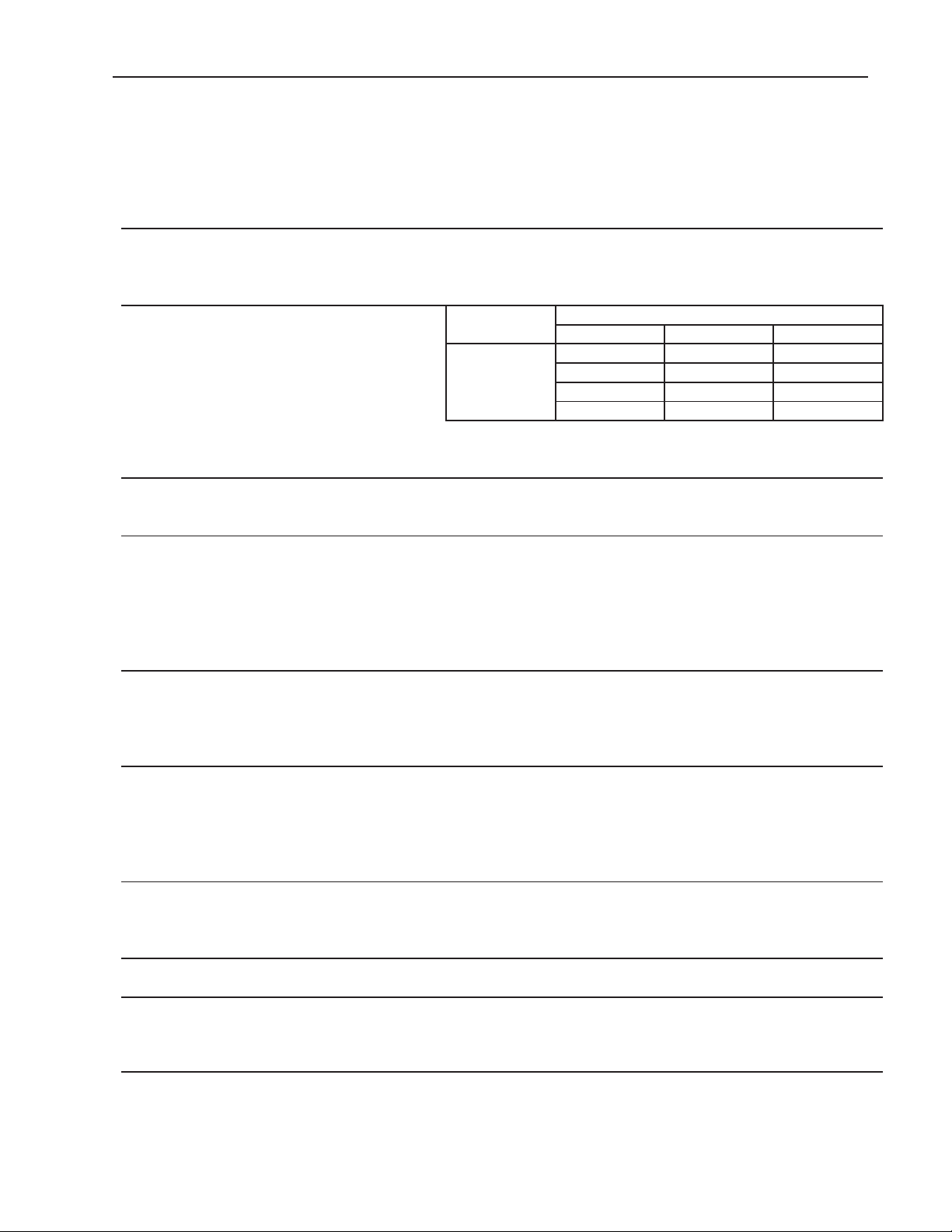
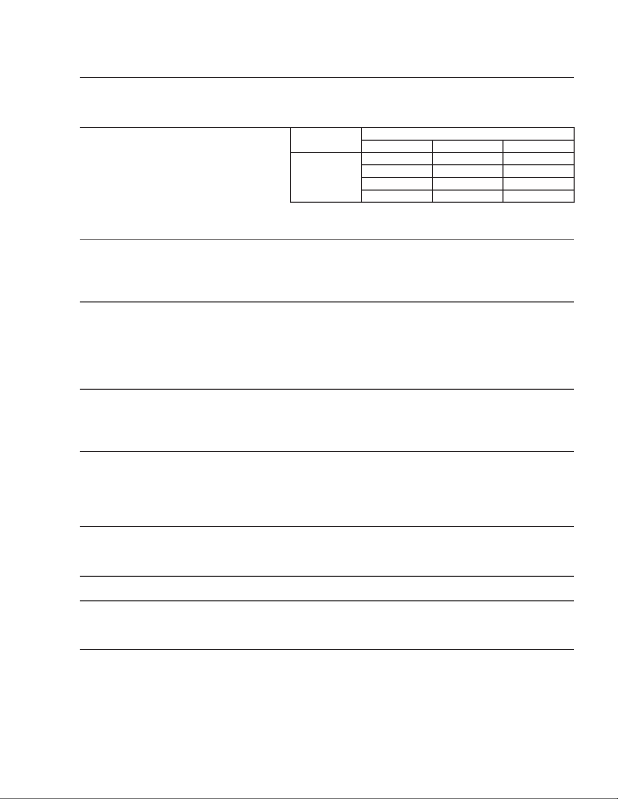
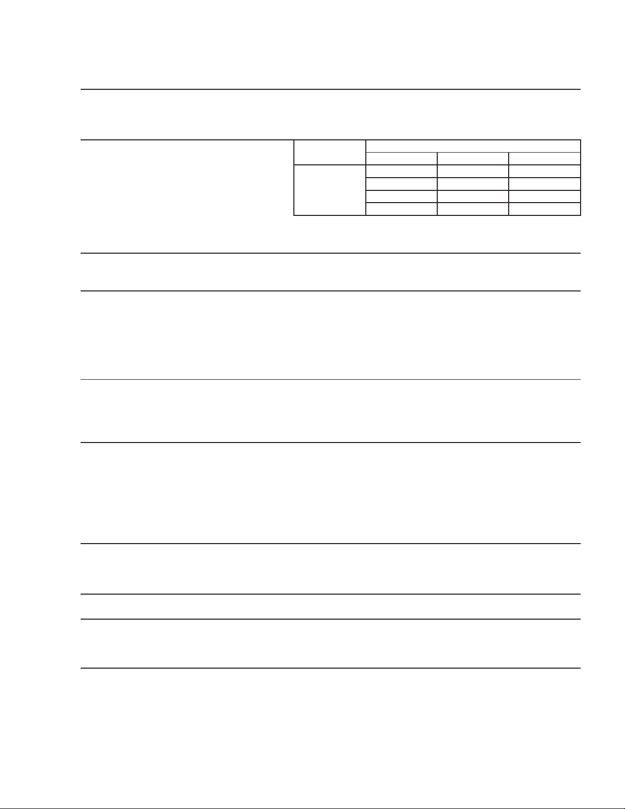
1a. KM-901MAH (air-cooled) Auxiliary Code T-0, U-0
AC SUPPLY VOLTAGE 208-230/60/1 (3 wire with netrual for 115V)
AMPERAGE 11.4 A ( 5 Min. Freeze AT 104°F / WT 80°F)
MINIMUM CIRCUIT AMPACITY 20 A
MAXIMUM FUSE SIZE 20 A
APPROXIMATE ICE PRODUCTION Ambient WATER TEMP. (°F)
PER 24 HR. Temp.(°F) 50 70 90
lbs./day ( kg/day ) 70 *874 (396) 832 (378) 785 (356)
Reference without *marks 80 842 (382) 778 (353) 736 (334)
90 832 (378) *732 (332) 687 (312)
100 826 (375) 721 (327) 646 (293)
SHAPE OF ICE Crescent Cube
ICE PRODUCTION PER CYCLE 13.6 lbs. (6.2 kg) 720pcs.
APPROXIMATE STORAGE CAPACITY N/A
ELECTRIC & WATER CONSUMPTION 90/70°F 70/50°F
ELECTRIC W (kWH/100 lbs.) 1710(5.6) 1600(4.4)
WATER gal./24HR (gal./100 lbs.) 143(19.6) 240(27.5)
EXTERIOR DIMENSIONS (WxDxH) 30" x 27-3/8" x 37-7/16" (762 x 695 x 950 mm)
EXTERIOR FINISH Stainless Steel, Galvanized Steel (Rear)
WEIGHT Net 196 lbs. (89 kg), Shipping 256 lbs. (116 kg)
CONNECTIONS - ELECTRIC Permanent - Connection
- WATER SUPPLY Inlet 1/2" FPT
- DRAIN Outlet 3/4" FPT
3/8" OD Tube
CUBE CONTROL SYSTEM Float Switch
HARVESTING CONTROL SYSTEM Hot Gas and Water, Thermistor and Timer
ICE MAKING WATER CONTROL Timer Controlled. Overflow Pipe
COOLING WATER CONTROL N/A
BIN CONTROL SYSTEM Thermostat
COMPRESSOR Hermetic, Model CS12K6E-PFV-237
CONDENSER Air-Cooled , Fin and tube type
EVAPORATOR Vertical type, Stainless Steel and Copper
REFRIGERANT CONTROL Thermostatic Expansion Valve
REFRIGERANT CHARGE R404A, 2 lb. 15 oz. (1320g)
DESIGN PRESSURE High 467PSIG, Low 230PSIG
P.C. BOARD CIRCUIT PROTECTION High Voltage Cut-out ( Internal )
COMPRESSOR PROTECTION Auto-reset Overload Protector ( Internal )
REFRIGERANT CIRCUIT PROTECTION Auto-reset High Pressure Control Switch
LOW WATER PROTECTION Float Switch
ACCESSORIES -SUPPLIED N/A
-REQUIRED Ice Storage Bin
OPERATING CONDITIONS VOLTAGE RANGE 187 - 253 V
AMBIENT TEMP. 45 -100° F
WATER SUPPLY TEMP. 45 - 90° F
WATER SUPPLY PRESSURE 10 - 113 PSIG
Note: We reserve the right to make changes in specications and design without prior
notice.
7
Page 8
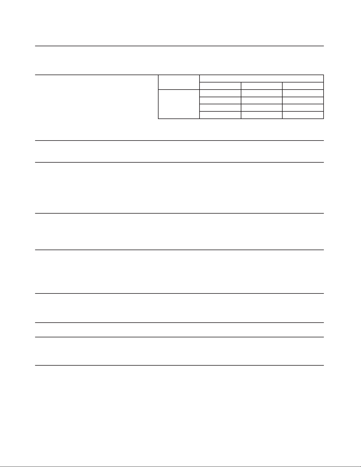
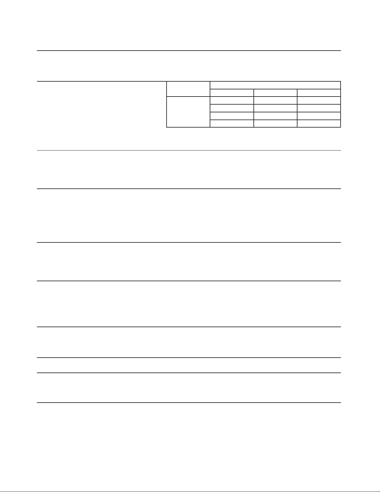
1b. KM-901MAH (air-cooled) Auxiliary Code U-1 and Later
AC SUPPLY VOLTAGE 208-230/60/1 (3 wire with netrual for 115V)
AMPERAGE 11.4 A ( 5 Min. Freeze AT 104°F / WT 80°F)
MINIMUM CIRCUIT AMPACITY 20 A
MAXIMUM FUSE SIZE 20 A
APPROXIMATE ICE PRODUCTION Ambient WATER TEMP. (°F)
PER 24 HR. Temp.(°F) 50 70 90
lbs./day ( kg/day ) 70 *874 (396) 832 (378) 785 (356)
Reference without *marks 80 842 (382) 778 (353) 736 (334)
90 832 (378) *732 (332) 687 (312)
100 826 (375) 721 (327) 646 (293)
SHAPE OF ICE Crescent Cube
ICE PRODUCTION PER CYCLE 13.6 lbs. (6.2 kg) 720pcs.
APPROXIMATE STORAGE CAPACITY N/A
ELECTRIC & WATER CONSUMPTION 90/70°F 70/50°F
ELECTRIC W (kWH/100 lbs.) 1710(5.6) 1600(4.4)
WATER gal./24HR (gal./100 lbs.) 143(19.6) 240(27.5)
EXTERIOR DIMENSIONS (WxDxH) 30" x 27-3/8" x 37-7/16" (762 x 695 x 950 mm)
EXTERIOR FINISH Stainless Steel, Galvanized Steel (Rear)
WEIGHT Net 196 lbs. (89 kg), Shipping 256 lbs. (116 kg)
CONNECTIONS - ELECTRIC Permanent - Connection
- WATER SUPPLY Inlet 1/2" FPT
- DRAIN Outlet 3/4" FPT
3/8" OD Tube
CUBE CONTROL SYSTEM Float Switch
HARVESTING CONTROL SYSTEM Hot Gas and Water, Thermistor and Timer
ICE MAKING WATER CONTROL Timer Controlled. Overflow Pipe
COOLING WATER CONTROL N/A
BIN CONTROL SYSTEM Mechanical Switch
COMPRESSOR Hermetic, Model CS12K6E-PFV-237
CONDENSER Air-Cooled , Fin and tube type
EVAPORATOR Vertical type, Stainless Steel and Copper
REFRIGERANT CONTROL Thermostatic Expansion Valve
REFRIGERANT CHARGE R404A, 2 lb. 15 oz. (1320g)
DESIGN PRESSURE High 467PSIG, Low 230PSIG
P.C. BOARD CIRCUIT PROTECTION High Voltage Cut-out ( Internal )
COMPRESSOR PROTECTION Auto-reset Overload Protector ( Internal )
REFRIGERANT CIRCUIT PROTECTION Auto-reset High Pressure Control Switch
LOW WATER PROTECTION Float Switch
ACCESSORIES -SUPPLIED N/A
-REQUIRED Ice Storage Bin
OPERATING CONDITIONS VOLTAGE RANGE 187 - 253 V
AMBIENT TEMP. 45 -100° F
WATER SUPPLY TEMP. 45 - 90° F
WATER SUPPLY PRESSURE 10 - 113 PSIG
Note: We reserve the right to make changes in specications and design without prior
notice.
8
Page 9
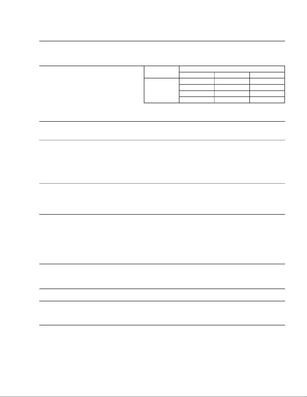
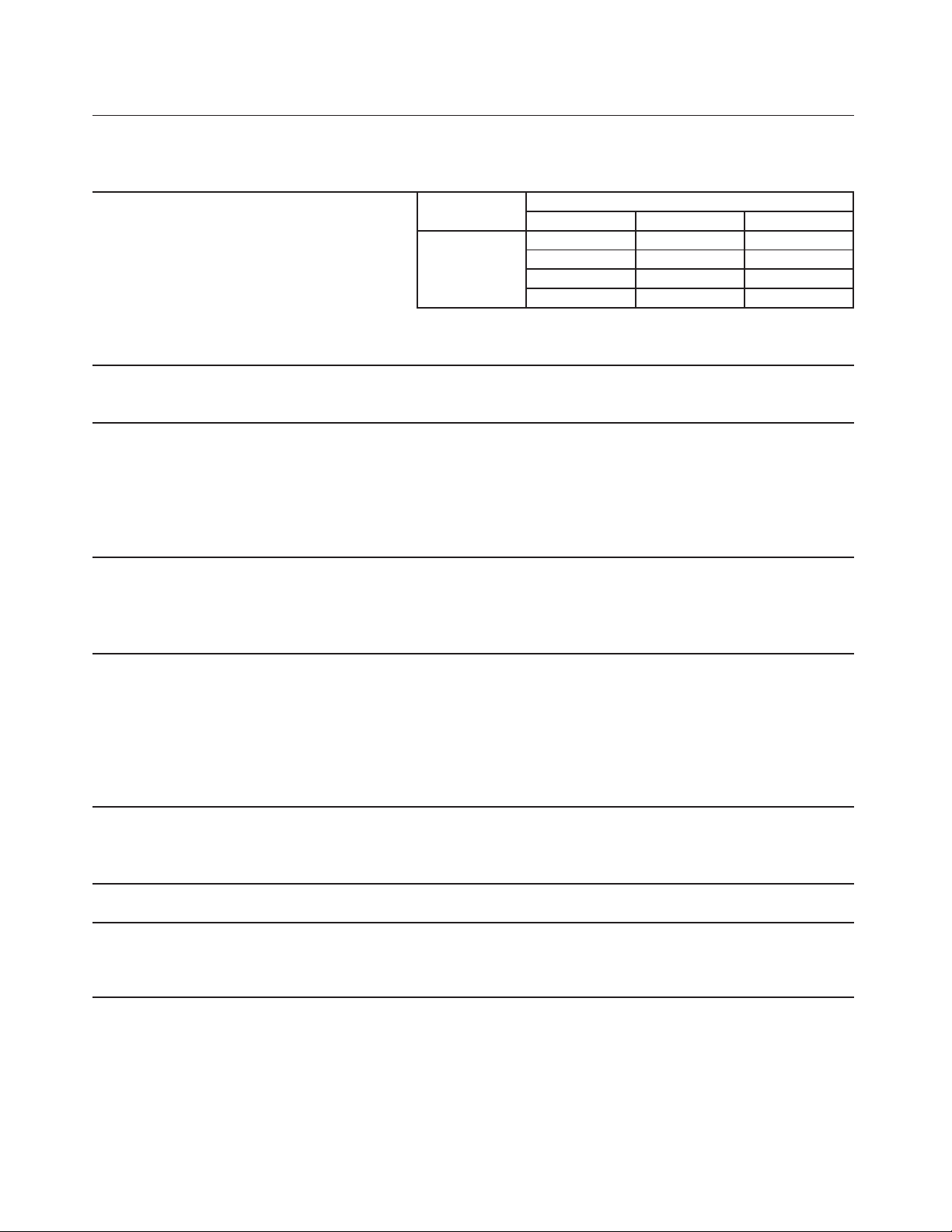
2a. KM-901MWH (water-cooled) Auxiliary Code T-0, U-0
AC SUPPLY VOLTAGE 208-230/60/1 (3 wire with netrual for 115V)
AMPERAGE 8.7A ( 5 Min. Freeze AT 104°F / WT 80°F)
MINIMUM CIRCUIT AMPACITY 15 A
MAXIMUM FUSE SIZE 15 A
APPROXIMATE ICE PRODUCTION Ambient WATER TEMP. (°F)
PER 24 HR. Temp.(°F) 50 70 90
lbs./day ( kg/day ) 70 *912 (414) 889 (403) 849 (385)
Reference without *marks 80 895 (406) 860 (390) 815 (370)
90 889 (403) *835 (379) 791 (359)
100 878 (398) 825 (374) 751 (341)
SHAPE OF ICE Crescent Cube
ICE PRODUCTION PER CYCLE 13.4 lbs. (6.1 kg) 720pcs.
APPROXIMATE STORAGE CAPACITY N/A
ELECTRIC & WATER CONSUMPTION 90/70°F 70/50°F
ELECTRIC W (kWH/100 lbs.) 1570(4.5) 1480(3.9)
WATER gal./24HR (gal./100 lbs.) 182(21.8) 245(26.9)
WATER COOLED CONDENSER 1162(139) 631(69)
gal./24HR (gal./100 lbs.)
EXTERIOR DIMENSIONS (WxDxH) 30" x 27-3/8" x 37-7/16" (762 x 695 x 950 mm)
EXTERIOR FINISH Stainless Steel, Galvanized Steel (Rear)
WEIGHT Net 189 lbs. (86 kg), Shipping 249 lbs. (113 kg)
CONNECTIONS - ELECTRIC Permanent - Connection
- WATER SUPPLY Inlet 1/2" FPT Cond. Inlet 1/2" FPT
- DRAIN Outlet 3/4" FPT Cond. Outlet 3/8" FPT
3/8" OD Tube
CUBE CONTROL SYSTEM Float Switch
HARVESTING CONTROL SYSTEM Hot Gas and Water, Thermistor and Timer
ICE MAKING WATER CONTROL Timer Controlled. Overflow Pipe
COOLING WATER CONTROL Pressure Regulator
BIN CONTROL SYSTEM Thermostat
COMPRESSOR Hermetic, Model CS12K6E-PFV-237
CONDENSER Water-cooled, Tube in tube type
EVAPORATOR Vertical type, Stainless Steel and Copper
REFRIGERANT CONTROL Thermostatic Expansion Valve
REFRIGERANT CHARGE R404A, 1 lb. 15.4 oz. (890g)
DESIGN PRESSURE High 427PSIG, Low 230PSIG
P.C. BOARD CIRCUIT PROTECTION High Voltage Cut-out ( Internal )
COMPRESSOR PROTECTION Auto-reset Overload Protector ( Internal )
REFRIGERANT CIRCUIT PROTECTION Auto-reset High Pressure Control Switch
LOW WATER PROTECTION Float Switch
ACCESSORIES -SUPPLIED N/A
-REQUIRED Ice Storage Bin
OPERATING CONDITIONS VOLTAGE RANGE 187 - 253 V
AMBIENT TEMP. 45 -100° F
WATER SUPPLY TEMP. 45 - 90° F
WATER SUPPLY PRESSURE 10 - 113 PSIG
Note: We reserve the right to make changes in specications and design without prior
notice.
9
Page 10
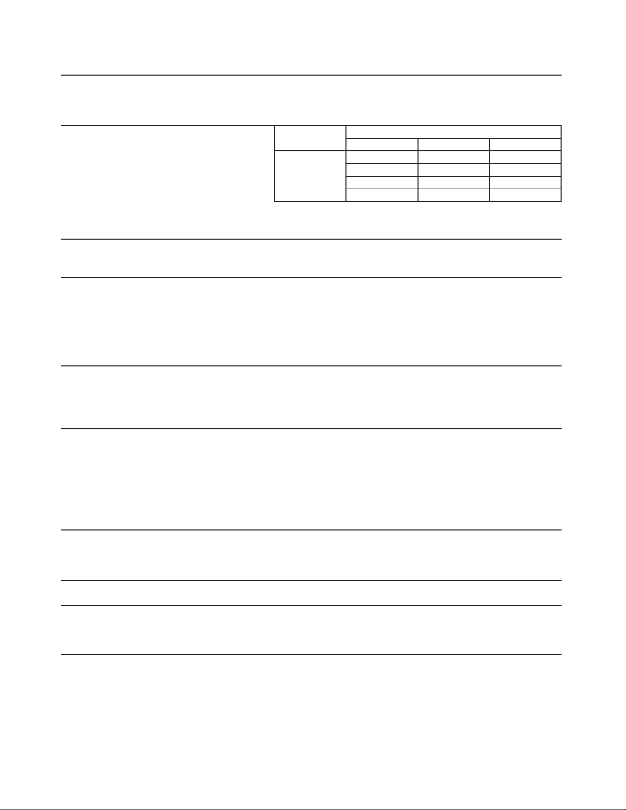
2b. KM-901MWH (water-cooled) Auxiliary Code U-1 and Later
AC SUPPLY VOLTAGE 208-230/60/1 (3 wire with netrual for 115V)
AMPERAGE 8.7A ( 5 Min. Freeze AT 104°F / WT 80°F)
MINIMUM CIRCUIT AMPACITY 15 A
MAXIMUM FUSE SIZE 15 A
APPROXIMATE ICE PRODUCTION Ambient WATER TEMP. (°F)
PER 24 HR. Temp.(°F) 50 70 90
lbs./day ( kg/day ) 70 *912 (414) 889 (403) 849 (385)
Reference without *marks 80 895 (406) 860 (390) 815 (370)
90 889 (403) *835 (379) 791 (359)
100 878 (398) 825 (374) 751 (341)
SHAPE OF ICE Crescent Cube
ICE PRODUCTION PER CYCLE 13.4 lbs. (6.1 kg) 720pcs.
APPROXIMATE STORAGE CAPACITY N/A
ELECTRIC & WATER CONSUMPTION 90/70°F 70/50°F
ELECTRIC W (kWH/100 lbs.) 1570(4.5) 1480(3.9)
WATER gal./24HR (gal./100 lbs.) 182(21.8) 245(26.9)
WATER COOLED CONDENSER 1162(139) 631(69)
gal./24HR (gal./100 lbs.)
EXTERIOR DIMENSIONS (WxDxH) 30" x 27-3/8" x 37-7/16" (762 x 695 x 950 mm)
EXTERIOR FINISH Stainless Steel, Galvanized Steel (Rear)
WEIGHT Net 189 lbs. (86 kg), Shipping 249 lbs. (113 kg)
CONNECTIONS - ELECTRIC Permanent - Connection
- WATER SUPPLY Inlet 1/2" FPT Cond. Inlet 1/2" FPT
- DRAIN Outlet 3/4" FPT Cond. Outlet 3/8" FPT
3/8" OD Tube
CUBE CONTROL SYSTEM Float Switch
HARVESTING CONTROL SYSTEM Hot Gas and Water, Thermistor and Timer
ICE MAKING WATER CONTROL Timer Controlled. Overflow Pipe
COOLING WATER CONTROL Pressure Regulator
BIN CONTROL SYSTEM Mechanical Switch
COMPRESSOR Hermetic, Model CS12K6E-PFV-237
CONDENSER Water-cooled, Tube in tube type
EVAPORATOR Vertical type, Stainless Steel and Copper
REFRIGERANT CONTROL Thermostatic Expansion Valve
REFRIGERANT CHARGE R404A, 1 lb. 15.4 oz. (890g)
DESIGN PRESSURE High 427PSIG, Low 230PSIG
P.C. BOARD CIRCUIT PROTECTION High Voltage Cut-out ( Internal )
COMPRESSOR PROTECTION Auto-reset Overload Protector ( Internal )
REFRIGERANT CIRCUIT PROTECTION Auto-reset High Pressure Control Switch
LOW WATER PROTECTION Float Switch
ACCESSORIES -SUPPLIED N/A
-REQUIRED Ice Storage Bin
OPERATING CONDITIONS VOLTAGE RANGE 187 - 253 V
AMBIENT TEMP. 45 -100° F
WATER SUPPLY TEMP. 45 - 90° F
WATER SUPPLY PRESSURE 10 - 113 PSIG
Note: We reserve the right to make changes in specications and design without prior
notice.
10
Page 11
3a. KM-901MRH (remote air-cooled) Auxiliary Code T-0, U-0
AC SUPPLY VOLTAGE 208-230/60/1 (3 wire with netrual for 115V)
AMPERAGE 11.6A ( 5 Min. Freeze AT 104°F / WT 80°F)
MINIMUM CIRCUIT AMPACITY 20 A
MAXIMUM FUSE SIZE 20 A
APPROXIMATE ICE PRODUCTION Ambient WATER TEMP. (°F)
PER 24 HR. Temp.(°F) 50 70 90
lbs./day ( kg/day ) 70 *889 (403) 859 (389) 803 (364)
Reference without *marks 80 866 (393) 818 (371) 755 (343)
90 859 (389) *785 (356) 724 (328)
100 843 (382) 771 (350) 668 (303)
SHAPE OF ICE Crescent Cube
ICE PRODUCTION PER CYCLE 13.5 lbs. (6.1 kg) 720pcs.
APPROXIMATE STORAGE CAPACITY N/A
ELECTRIC & WATER CONSUMPTION 90/70°F 70/50°F
ELECTRIC W (kWH/100 lbs.) 1770(5.4) 1590(4.3)
WATER gal./24HR (gal./100 lbs.) 152(19.3) 246(27.7)
EXTERIOR DIMENSIONS (WxDxH) 30" x 27-3/8" x 37-7/16" (762 x 695 x 950 mm)
EXTERIOR FINISH Stainless Steel, Galvanized Steel (Rear)
WEIGHT Net 189 lbs. (86 kg), Shipping 249 lbs. (113 kg)
CONNECTIONS - ELECTRIC Permanent - Connection
- WATER SUPPLY Inlet 1/2" FPT
- DRAIN Outlet 3/4" FPT
3/8" OD Tube
CUBE CONTROL SYSTEM Float Switch
HARVESTING CONTROL SYSTEM Hot Gas and Water, Thermistor and Timer
ICE MAKING WATER CONTROL Timer Controlled. Overflow Pipe
COOLING WATER CONTROL N/A
BIN CONTROL SYSTEM Thermostat
COMPRESSOR Hermetic, Model CS12K6E-PFV-279
CONDENSER Air-Cooled Remote, Condenser Unit URC-9F
EVAPORATOR Vertical type, Stainless Steel and Copper
REFRIGERANT CONTROL Thermostatic Expansion Valve
Condensing Pressure Regulator on URC-9F
REFRIGERANT CHARGE R404A, 9 lbs. 4 oz. (4200g)
(Icemaker 5 lbs. 5 oz. Cond. Unit 3 lbs. 15 oz.)
DESIGN PRESSURE High 467PSIG, Low 230PSIG
P.C. BOARD CIRCUIT PROTECTION High Voltage Cut-out ( Internal )
COMPRESSOR PROTECTION Auto-reset Overload Protector ( Internal )
REFRIGERANT CIRCUIT PROTECTION Auto-reset High Pressure Control Switch
LOW WATER PROTECTION Float Switch
ACCESSORIES -SUPPLIED N/A
-REQUIRED Ice Storage Bin, Remote Condenser Unit
OPERATING CONDITIONS VOLTAGE RANGE 187 - 253 V
AMBIENT TEMP. 45 -100° F
WATER SUPPLY TEMP. 45 - 90° F
WATER SUPPLY PRESSURE 10 - 113 PSIG
Note: We reserve the right to make changes in specications and design without prior
notice.
11
Page 12
3b. KM-901MRH (remote air-cooled) Auxiliary Code U-1 and Later
AC SUPPLY VOLTAGE 208-230/60/1 (3 wire with netrual for 115V)
AMPERAGE 11.6A ( 5 Min. Freeze AT 104°F / WT 80°F)
MINIMUM CIRCUIT AMPACITY 20 A
MAXIMUM FUSE SIZE 20 A
APPROXIMATE ICE PRODUCTION Ambient WATER TEMP. (°F)
PER 24 HR. Temp.(°F) 50 70 90
lbs./day ( kg/day ) 70 *889 (403) 859 (389) 803 (364)
Reference without *marks 80 866 (393) 818 (371) 755 (343)
90 859 (389) *785 (356) 724 (328)
100 843 (382) 771 (350) 668 (303)
SHAPE OF ICE Crescent Cube
ICE PRODUCTION PER CYCLE 13.5 lbs. (6.1 kg) 720pcs.
APPROXIMATE STORAGE CAPACITY N/A
ELECTRIC & WATER CONSUMPTION 90/70°F 70/50°F
ELECTRIC W (kWH/100 lbs.) 1770(5.4) 1590(4.3)
WATER gal./24HR (gal./100 lbs.) 152(19.3) 246(27.7)
EXTERIOR DIMENSIONS (WxDxH) 30" x 27-3/8" x 37-7/16" (762 x 695 x 950 mm)
EXTERIOR FINISH Stainless Steel, Galvanized Steel (Rear)
WEIGHT Net 189 lbs. (86 kg), Shipping 249 lbs. (113 kg)
CONNECTIONS - ELECTRIC Permanent - Connection
- WATER SUPPLY Inlet 1/2" FPT
- DRAIN Outlet 3/4" FPT
3/8" OD Tube
CUBE CONTROL SYSTEM Float Switch
HARVESTING CONTROL SYSTEM Hot Gas and Water, Thermistor and Timer
ICE MAKING WATER CONTROL Timer Controlled. Overflow Pipe
COOLING WATER CONTROL N/A
BIN CONTROL SYSTEM Mechanical Switch
COMPRESSOR Hermetic, Model CS12K6E-PFV-279
CONDENSER Air-Cooled Remote, Condenser Unit URC-9F
EVAPORATOR Vertical type, Stainless Steel and Copper
REFRIGERANT CONTROL Thermostatic Expansion Valve
Condensing Pressure Regulator on URC-9F
REFRIGERANT CHARGE R404A, 9 lbs. 4 oz. (4200g)
(Icemaker 5 lbs. 5 oz. Cond. Unit 3 lbs. 15 oz.)
DESIGN PRESSURE High 467PSIG, Low 230PSIG
P.C. BOARD CIRCUIT PROTECTION High Voltage Cut-out ( Internal )
COMPRESSOR PROTECTION Auto-reset Overload Protector ( Internal )
REFRIGERANT CIRCUIT PROTECTION Auto-reset High Pressure Control Switch
LOW WATER PROTECTION Float Switch
ACCESSORIES -SUPPLIED N/A
-REQUIRED Ice Storage Bin, Remote Condenser Unit
OPERATING CONDITIONS VOLTAGE RANGE 187 - 253 V
AMBIENT TEMP. 45 -100° F
WATER SUPPLY TEMP. 45 - 90° F
WATER SUPPLY PRESSURE 10 - 113 PSIG
Note: We reserve the right to make changes in specications and design without prior
notice.
12
Page 13
4a. KM-901MRH3 (remote air-cooled) Auxiliary Code T-0, U-0
AC SUPPLY VOLTAGE 208-230/60/3
AMPERAGE 7.0A ( 5 Min. Freeze AT 104°F / WT 80°F)
MINIMUM CIRCUIT AMPACITY 20 A
MAXIMUM FUSE SIZE 20 A
APPROXIMATE ICE PRODUCTION Ambient WATER TEMP. (°F)
PER 24 HR. Temp.(°F) 50 70 90
lbs./day ( kg/day ) 70 *899 (408) 874 (397) 817 (371)
Reference without *marks 80 880 (399) 842 (382) 772 (350)
90 874 (397) *815 (370) 749 (340)
100 855 (388) 800 (363) 689 (313)
SHAPE OF ICE Crescent Cube
ICE PRODUCTION PER CYCLE 14.2 lbs. (6.4 kg) 720pcs.
APPROXIMATE STORAGE CAPACITY N/A
ELECTRIC & WATER CONSUMPTION 90/70°F 70/50°F
ELECTRIC W (kWH/100 lbs.) 1830(5.4) 1670(4.5)
WATER gal./24HR (gal./100 lbs.) 147(18.0) 254(28.2)
EXTERIOR DIMENSIONS (WxDxH) 30" x 27-3/8" x 37-7/16" (762 x 695 x 950 mm)
EXTERIOR FINISH Stainless Steel, Galvanized Steel (Rear)
WEIGHT Net 198 lbs. (90 kg), Shipping 258 lbs. (117 kg)
CONNECTIONS - ELECTRIC Permanent - Connection
- WATER SUPPLY Inlet 1/2" FPT
- DRAIN Outlet 3/4" FPT
3/8" OD Tube
CUBE CONTROL SYSTEM Float Switch
HARVESTING CONTROL SYSTEM Hot Gas and Water, Thermistor and Timer
ICE MAKING WATER CONTROL Timer Controlled. Overflow Pipe
COOLING WATER CONTROL N/A
BIN CONTROL SYSTEM Thermostat
COMPRESSOR Hermetic, Model CS12K6E-TF5-279
CONDENSER Air-Cooled Remote, Condenser Unit URC-9F
EVAPORATOR Vertical type, Stainless Steel and Copper
REFRIGERANT CONTROL Thermostatic Expansion Valve
Condensing Pressure Regulator on URC-9F
REFRIGERANT CHARGE R404A, 9 lbs. 4 oz. (4200g)
(Icemaker 5 lbs. 5 oz. Cond. Unit 3 lbs. 15 oz.)
DESIGN PRESSURE High 467PSIG, Low 230PSIG
P.C. BOARD CIRCUIT PROTECTION High Voltage Cut-out ( Internal )
COMPRESSOR PROTECTION Auto-reset Overload Protector ( Internal )
REFRIGERANT CIRCUIT PROTECTION Auto-reset High Pressure Control Switch
LOW WATER PROTECTION Float Switch
ACCESSORIES -SUPPLIED N/A
-REQUIRED Ice Storage Bin, Remote Condenser Unit
OPERATING CONDITIONS VOLTAGE RANGE 187 - 253 V
AMBIENT TEMP. 45 -100° F
WATER SUPPLY TEMP. 45 - 90° F
WATER SUPPLY PRESSURE 10 - 113 PSIG
Note: We reserve the right to make changes in specications and design without prior
notice.
13
Page 14
4b. KM-901MRH (remote air-cooled) Auxiliary Code U-1 and Later
AC SUPPLY VOLTAGE 208-230/60/3
AMPERAGE 7.0A ( 5 Min. Freeze AT 104°F / WT 80°F)
MINIMUM CIRCUIT AMPACITY 20 A
MAXIMUM FUSE SIZE 20 A
APPROXIMATE ICE PRODUCTION Ambient WATER TEMP. (°F)
PER 24 HR. Temp.(°F) 50 70 90
lbs./day ( kg/day ) 70 *899 (408) 874 (397) 817 (371)
Reference without *marks 80 880 (399) 842 (382) 772 (350)
90 874 (397) *815 (370) 749 (340)
100 855 (388) 800 (363) 689 (313)
SHAPE OF ICE Crescent Cube
ICE PRODUCTION PER CYCLE 14.2 lbs. (6.4 kg) 720pcs.
APPROXIMATE STORAGE CAPACITY N/A
ELECTRIC & WATER CONSUMPTION 90/70°F 70/50°F
ELECTRIC W (kWH/100 lbs.) 1830(5.4) 1670(4.5)
WATER gal./24HR (gal./100 lbs.) 147(18.0) 254(28.2)
EXTERIOR DIMENSIONS (WxDxH) 30" x 27-3/8" x 37-7/16" (762 x 695 x 950 mm)
EXTERIOR FINISH Stainless Steel, Galvanized Steel (Rear)
WEIGHT Net 198 lbs. (90 kg), Shipping 258 lbs. (117 kg)
CONNECTIONS - ELECTRIC Permanent - Connection
- WATER SUPPLY Inlet 1/2" FPT
- DRAIN Outlet 3/4" FPT
3/8" OD Tube
CUBE CONTROL SYSTEM Float Switch
HARVESTING CONTROL SYSTEM Hot Gas and Water, Thermistor and Timer
ICE MAKING WATER CONTROL Timer Controlled. Overflow Pipe
COOLING WATER CONTROL N/A
BIN CONTROL SYSTEM Mechanical Switch
COMPRESSOR Hermetic, Model CS12K6E-TF5-279
CONDENSER Air-Cooled Remote, Condenser Unit URC-9F
EVAPORATOR Vertical type, Stainless Steel and Copper
REFRIGERANT CONTROL Thermostatic Expansion Valve
Condensing Pressure Regulator on URC-9F
REFRIGERANT CHARGE R404A, 9 lbs. 4 oz. (4200g)
(Icemaker 5 lbs. 5 oz. Cond. Unit 3 lbs. 15 oz.)
DESIGN PRESSURE High 467PSIG, Low 230PSIG
P.C. BOARD CIRCUIT PROTECTION High Voltage Cut-out ( Internal )
COMPRESSOR PROTECTION Auto-reset Overload Protector ( Internal )
REFRIGERANT CIRCUIT PROTECTION Auto-reset High Pressure Control Switch
LOW WATER PROTECTION Float Switch
ACCESSORIES -SUPPLIED N/A
-REQUIRED Ice Storage Bin, Remote Condenser Unit
OPERATING CONDITIONS VOLTAGE RANGE 187 - 253 V
AMBIENT TEMP. 45 -100° F
WATER SUPPLY TEMP. 45 - 90° F
WATER SUPPLY PRESSURE 10 - 113 PSIG
Note: We reserve the right to make changes in specications and design without prior
notice.
14
Page 15
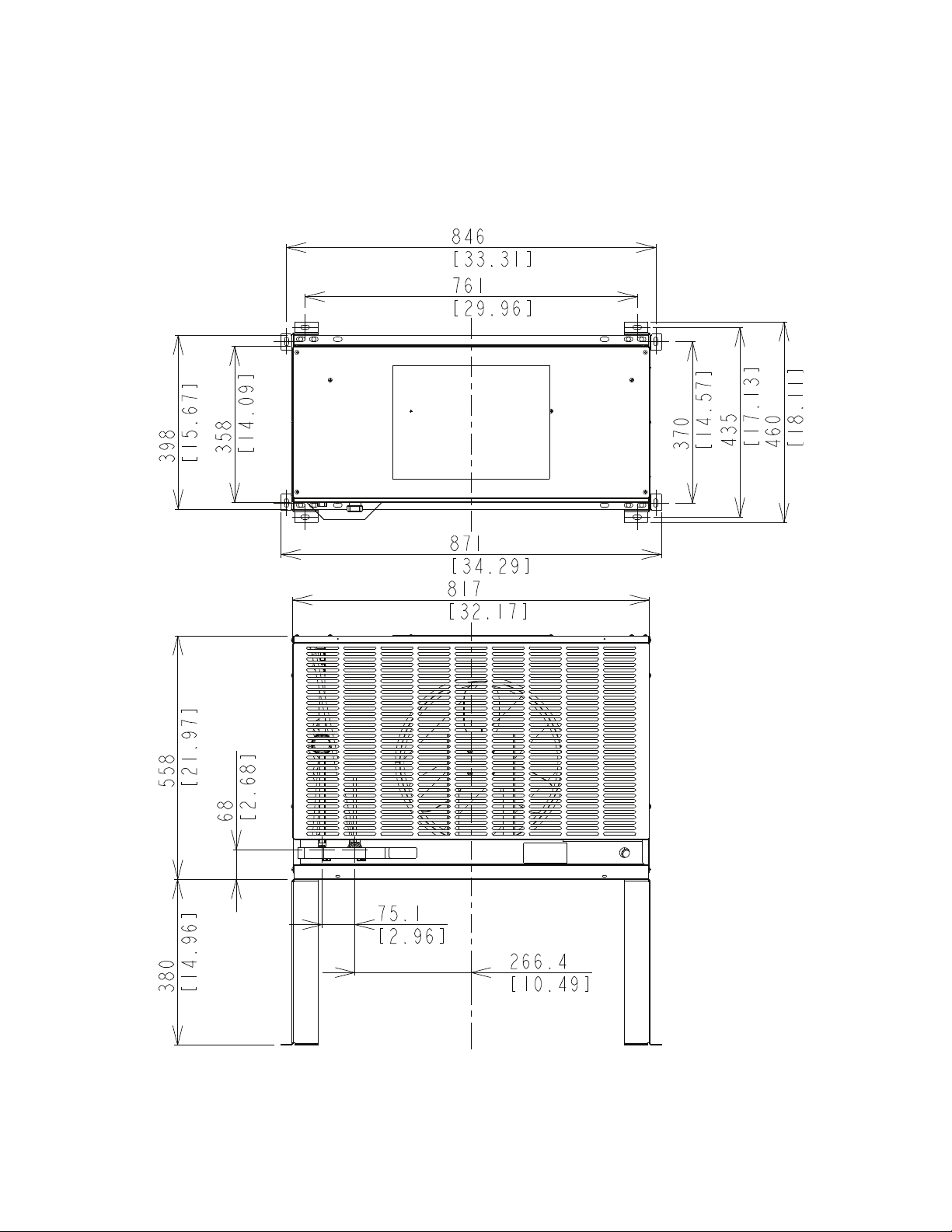
B. Condenser Unit
1. URC-9F
Unit: mm [in.]
15
Page 16

Specications
MODEL: URC-9F
AC SUPPLY VOLTAGE 115/60/1 (Connection to Icemaker)
FAN MOTOR 115 V Total 1.3FLA 65W
EXTERIOR DIMENSIONS (WxDxH) 32-3/16" x 15-11/16" x 21-15/16" (817 x 398 x 558 mm)
DIMENSIONS INCLUDING LEGS (WxDxH) 34-5/16" x 18-1/8" x 36-15/16" (871 x 460 x 938 mm)
EXTERIOR FINISH Galvanized Steel
WEIGHT Net 81 lbs. ( 37 kg ) Shipping 92 lbs. ( 42 kg )
CONNECTIONS - ELECTRIC Permanent - Connection
- REFRIGERANT Discharge Line 1-1/16"-12 UNF Fitting (#10 AEROQUIP)
Liquid Line 5/8"-18 UNF Fitting (#6 AEROQUIP)
CONDENSER Air-cooled, Fin and tube type
FAN MOTOR PROTECTION Thermal Protection
REFRIGERANT CONTROL Condensing Pressure Regulator
REFRIGERANT CHARGE R-404A 3 lbs. 14.8 oz. (1780g)
DESIGN PRESSURE High 467 PSIG
OPERATING CONDITIONS VOLTAGE RANGE 104 ~ 127 V
AMBIENT TEMP. -20 ~ 122 °F
ACCESSORIES -SUPPLIED Leg 2 pcs
Hex. Head Bolt w/Washer 8 x 16 8 pcs
Hex. Nut 8 8 pcs
Note: We reserve the right to make changes in specications and design without prior
notice.
16
Page 17
II. General Information
A. Construction
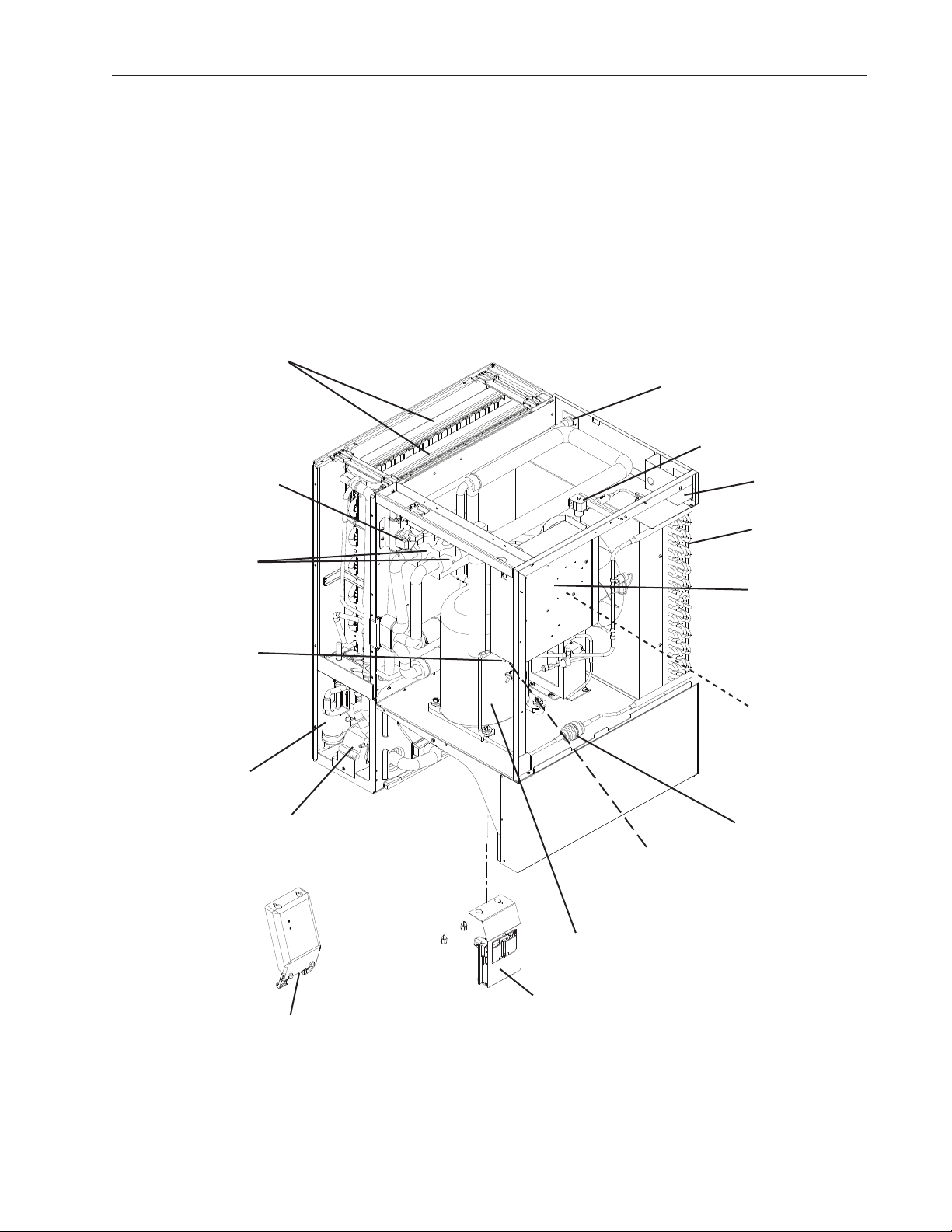
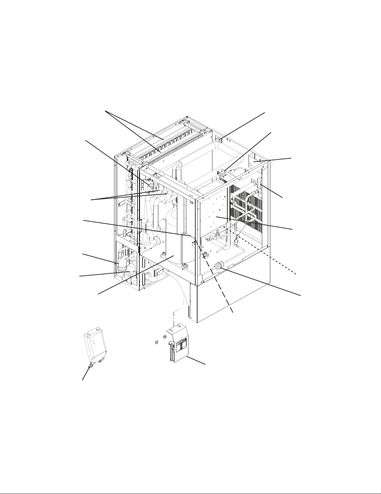
1. KM-901MAH (air-cooled)
Spray Tubes
Water Supply Inlet
Hot Gas Valve
Cleaning Valve
Expansion Valves
Control Switch
Float Switch
Water Pump
Junction Box
Condenser
Control Box
Fan Motor
Drier
Thermostatic Bin Control
Auxiliary Code T-0, U-0
Thermostatic Bin Control
Bracket & Bulb Holder
Auxiliary Code T-0, U-0
Compressor
Mechanical Bin Control and Bracket
Auxiliary Code U-1 and later
17
Page 18
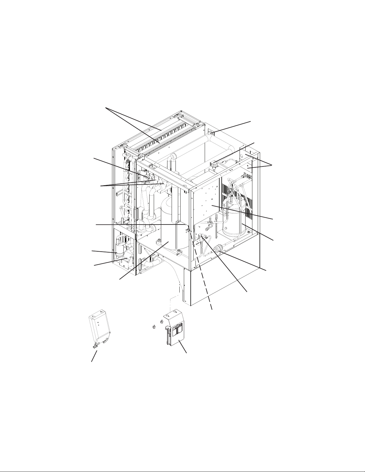
2. KM-901MWH (water-cooled)
Spray Tubes
Cleaning Valve
Expansion Valves
Control Switch
Float Switch
Water Pump
Water Supply Inlet
Hot Gas Valve
Junction
Box
Water Regulating
Valve
Control Box
Condenser
Compressor
Thermostatic Bin Control
Bracket & Bulb Holder
Auxiliary Code T-0, U-0
Drier
Thermostatic Bin Control
Auxiliary Code T-0, U-0
Mechanical Bin Control and Bracket
Auxiliary Code U-1 and later
18
Page 19
3. KM-901MRH/3 (remote air-cooled)
Spray Tubes
Cleaning Valve
Expansion Valves
Water Supply Inlet
Hot Gas Valve
Junction Boxes
Control Switch
Float Switch
Water Pump
Compressor
Thermostatic Bin Control
Bracket & Bulb Holder
Auxiliary Code T-0, U-0
Control Box
Receiver Tank
Drier
Liquid Line Valve
Thermostatic Bin Control
Auxiliary Code T-0, U-0
Mechanical Bin Control and Bracket
Auxiliary Code U-1 and later
19
Page 20

B. Sequence of Operation
1. Sequence Cycles and Shutdown
a) "E" Control Board: Auxiliary Code T-0, U-0
The steps in the sequence are as outlined below. When power is supplied, CB red
"POWER OK" LED comes on. There is a 5-second delay before startup. Note that the
order of the component LEDs from the outer edge of CB is 1, 4, 3, 2.
(1) 1-Minute Fill Cycle
LED 4 is on. WV energizes and the 1-minute ll cycle begins. After 1 minute, CB
checks for a closed F/S. If F/S is closed, the harvest cycle begins. If not, WV remains
energized through additional 1-minute ll cycles until water lls the tank and closes
F/S. This serves as a low water safety to protect PM.
(2) Initial Harvest Cycle
LEDs 1, 4, and 2 are on. WV remains energized, Comp, FMR, HGV energize. CB
monitors the warming of the evaporator via the thermistor located on the suction
line. When the thermistor reaches 48°F (9°C), CB reads a 3.9 kΩ signal from
the thermistor and turns harvest termination over to the harvest timer (S4 dip
switch 1 & 2). The harvest timer has settings of 60, 90, 120, and 180 seconds. For
details, see "II.C.3.b) Harvest Timer (S4 dip switch 1 & 2)." WV is energized during
harvest for a maximum of 6 minutes or the length of harvest, whichever is shorter.
LED 4 goes off when WV de-energizes. When the harvest timer expires, the harvest
cycle is complete. CB checks the position of F/S and proceeds to the next cycle if it
is closed or calls for a 1-minute ll cycle if it is open. The minimum total time allowed
by CB for a complete harvest cycle is 2 minutes.
(3) Freeze Cycle
LED 1 is on. Comp and FMR remain energized, PM, FM, and LLV energize, HGV
and WV de-energize. For the rst 5 minutes, CB will not accept a signal from F/S.
This minimum 5-minute freeze time is short cycle protection for Comp. At the end of
5 minutes, F/S assumes control. As ice builds on the evaporator, the water level in
the tank lowers. The freeze cycle continues until F/S opens and terminates the cycle.
(4) Pump-Out Cycle
LEDs 1, 3, and 2 are on. LED 4 is on when S4 dip switch 3 & 4 are set to 3 off and
4 on. Comp and FMR remain energized. HGV energizes. WV energizes if S4 dip
switch 3 off and 4 on. LLV and FM de-energize. PM stops for 2 seconds then
reverses, taking water from the bottom of the tank and forcing pressure against the
check valve seat allowing water to go through the check valve and down the drain.
At the same time, water ows through the small tube to power ush F/S. When the
pump-out timer expires, the pump-out is complete.
The rst pump-out occurs after the 1st freeze cycle, then every 10th cycle thereafter.
The pump-out frequency is factory set, and generally no adjustment is required.
However, where water quality is bad and the icemaker needs a pump-out more
often, the pump-out frequency can be adjusted. The pump-out frequency control
(S4 dip switch 5 & 6) can be set to have a pump-out occur every cycle, or every
2, 5, or 10 cycles. For details, see "II.C.3.d) Pump-Out Frequency Control (S4 dip
switch 5 & 6)."
20
Page 21

(5) Harvest Cycle
Same as the initial harvest cycle. See "II.B.1.a)(2) Initial Harvest Cycle."
Note: Unit continues to cycle until TBC is satised or power is turned off. The unit
always restarts at the 1-minute ll cycle.
(6) Shutdown
When ice contacts the thermostatic bulb (TBC switch open), TBC shuts down the
unit within 10 seconds. TBC is factory set, and generally no adjustment is required.
However, adjustment may be needed in some conditions, particularly at higher
altitude locations. CAUTION! Do not adjust S4 dip switch 7 out of the factory
default position on this model. This dip switch must be left in the factory
default position or this unit will not operate correctly.
Legend: CB–control board; Comp–compressor; FM–fan motor;
FMR–fan motor-remote; F/S–oat switch; HGV–hot gas valve; LLV –liquid line
valve; PM–pump motor; TBC–thermostatic bin control; WV–inlet water valve
b) "G" Control Board: Auxiliary Code U-1 and Later
The steps in the sequence are as outlined below. When power is supplied, CB red
"POWER OK" LED and green "BC CLOSED" LED come on. There is a 5-second delay
before startup. Note that the order of the component LEDs from the outer edge of CB is
1, 4, 3, 2.
(1) 1-Minute Fill Cycle
LED 4 is on. WV energizes and the 1-minute ll cycle begins. After 1 minute, CB
checks for a closed F/S. If F/S is closed, the harvest cycle begins. If not, WV remains
energized through additional 1-minute ll cycles until water lls the tank and closes
F/S. This serves as a low water safety to protect PM.
(2) Initial Harvest Cycle
LEDs 1, 4, and 2 are on. WV remains energized, Comp, FMR, HGV energize. CB
monitors the warming of the evaporator via the thermistor located on the suction
line. When the thermistor reaches 48°F (9°C), CB reads a 3.9 kΩ signal from the
thermistor and turns harvest termination over to the harvest timer (S4 dip switch 1 &
2). The harvest timer has settings of 60, 90, 120, and 180 seconds. For details, see
"II.C.3.b) Harvest Timer (S4 dip switch 1 & 2)." WV is energized during harvest for a
maximum of 6 minutes or the length of harvest minus 0 or 50 seconds (harvest pump
timer (S4 dip switch 7)), whichever is shorter. CAUTION! Do not adjust S4 dip
switch 7 out of the factory default position on this model. This dip switch must
be left in the factory default position or this unit will not operate correctly. For
details, see "II.C.3.e) Bin Control Selector/Harvest Pump Timer (S4 dip switch 7)."
LED 4 goes off when WV de-energizes. LED 3 comes on and PM energizes and runs
for the last 0 or 50 seconds of harvest depending on S4 dip switch 7 setting. When
the harvest timer expires, the harvest cycle is complete. CB checks the position of
F/S and proceeds to the freeze cycle if it is closed or calls for a 1-minute ll cycle
if it is open. The minimum total time allowed by CB for a complete harvest cycle is
2 minutes.
21
Page 22
(3) Freeze Cycle
LED 1 is on. Comp and FMR remain energized, PM, FM, and LLV energize. HGV
and WV de-energize. For the rst 5 minutes, CB will not accept a signal from F/S.
This minimum 5-minute freeze time is short cycle protection for Comp. At the end of
5 minutes, F/S assumes control. As ice builds on the evaporator, the water level in
the tank lowers. The freeze cycle continues until F/S opens and terminates the cycle.
There is a 15 second delay before CB acknowledges an open F/S.
(4) Pump-Out Cycle
LEDs 1, 3, and 2 are on. LED 4 is on when S4 dip switch 3 & 4 are set to 3 off and
4 on. Comp and FMR remain energized, HGV energizes, WV energizes if S4 dip
switch 3 off and 4 on. LLV and FM de-energize. PM stops for 2 seconds then
reverses, taking water from the bottom of the tank and forcing pressure against the
check valve seat allowing water to go through the check valve and down the drain.
At the same time, water ows through the small tube to power ush F/S. When the
pump-out timer expires, the pump-out is complete.
The rst pump-out occurs after the 11th freeze cycle, then every 10th cycle
thereafter. The pump-out frequency control is factory set, and generally no
adjustment is required. However, where water quality is bad and the icemaker needs
a pump-out more often, the pump-out frequency can be adjusted. The pump-out
frequency control (S4 dip switch 5 & 6) can be set to have a pump-out occur every
cycle, or every 2, 5, or 10 cycles. Timing of the rst pump-out is dependent on S4
dip switch 5 & 6 settings. See the table below. For details, see "II.C.3.d) Pump-Out
Frequency Control (S4 dip switch 5 & 6)."
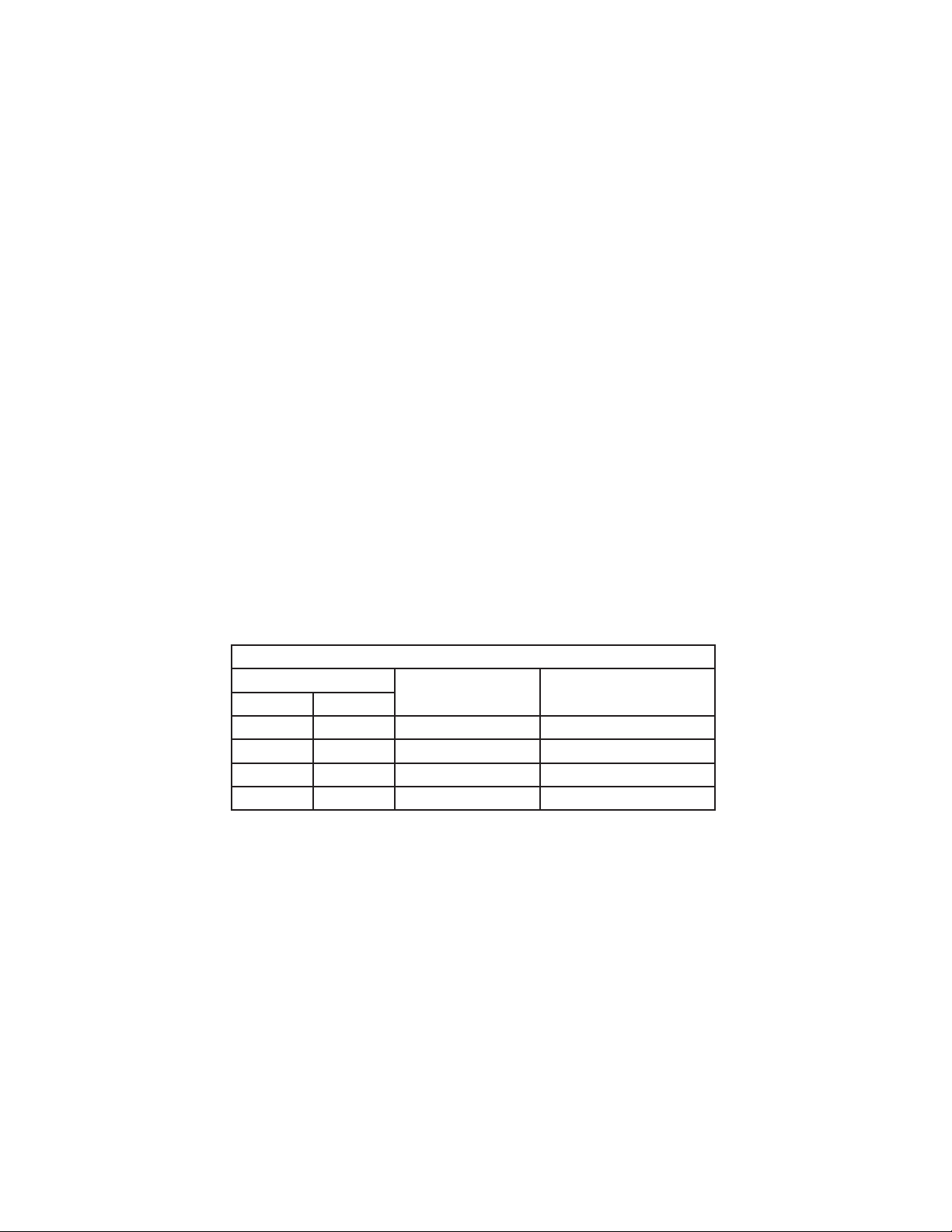
"G" Control Board Settings
S4 Dip Switch Setting
No. 5 No. 6
OFF OFF Every cycle After 2nd freeze cycle
ON OFF Every 2 cycles After 3rd freeze cycle
OFF ON Every 5 cycles After 6th freeze cycle
ON ON Every 10 cycles After 11th freeze cycle
Pump-Out
Frequency
1st Pump-Out
(5) Harvest Cycle
Same as the initial harvest cycle. See "II.B.1.b)(2) Initial Harvest Cycle."
Note: Unit continues to cycle until MBC is satised or power is turned off. The unit
always restarts at the 1-minute ll cycle.
22
Page 23
(6) Shutdown
When MBC is activated (MBC open), the yellow "BC OPEN" LED comes on. The unit
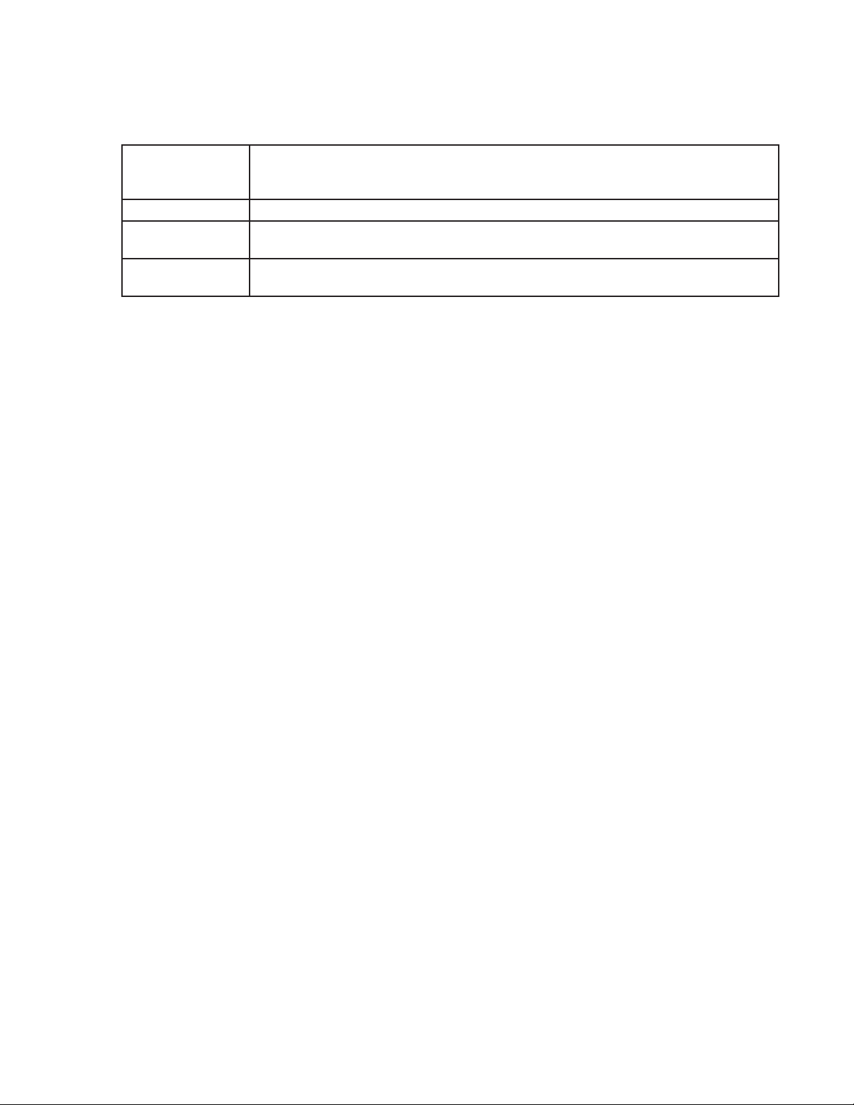
then shuts down as outlined in the table below.
Cycle at
Mechanical Bin
Control Activation
Fill Cycle 15 seconds after activation.
Harvest Cycle At the end of the harvest cycle, or up to 15 seconds into the freeze cycle if activated
Freeze Cycle 15 seconds after activation if activated at least 15 seconds before the 5-minute short
Shutdown
at the end of the harvest cycle.
cycle protection timer expires. Otherwise, at the end of the next harvest cycle.
Legend: CB–control board; Comp–compressor; FM–fan motor;
FMR–fan motor-remote; F/S–oat switch; HGV–hot gas valve; LLV –liquid line
valve; MBC–mechanical bin control; PM–pump motor; WV–inlet water valve
23
Page 24
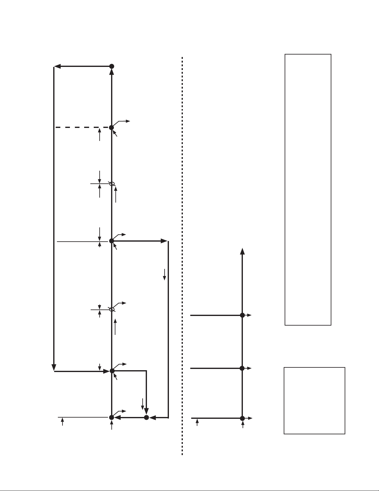
2. Sequence Flow Chart
a) "E" Control Board: Auxiliary Code T-0, U-0
10th cycle (S4 dip
switch 5 & 6)
for 2 sec., then
reverses for 10/20
sec. (S4 dip switch
F/S in control
3 & 4)
Comp continues
FMR continues
HGV energized
PM de-energizes for 2 sec.,
then reverses for 10/20 sec.
FM de-energized
LLV de-energized
F/S open or freeze
timer expires
4. Pump-Out Cycle
•Factorysetforevery
•Pumpmotorstops
KM-901MAH, KM-901MWH, KM-901MRH/3
"E" Control Board Sequence Flow Chart
2. Harvest Cycle 3. Freeze Cycle
1. 1-Minute Fill
•Minimumfreezetime:5min.
•WVtime:6min.orthelengthofharvest,
Cycle
5-min. timer
(S4 dip switch 9 & 10
•Maximumfreezetime:freezetimersetting
whichever is shorter.
•Maximumharvesttime:20min.
in control
1 to 3-min. timer in control
(S4 dip switch 1 & 2)
Thermistor in control
F/S closed
F/S Check
F/S closed
F/S Check
Comp continues
FMR continues
Thermistor temperature
reaches 48°F (9°C)
WV continues
Comp energized
WV energized
PM energized
(3.9 kΩ or less) Harvest
HGV energized
F/S open
FM energized
timer starts
FMR energized
LLV energized
HGV de-energized
WV de-energized
F/S open
If F/S is open, compressor stops and cycle returns to 1-Minute Fill Cycle
3. Ice Level Lowered
2. Icemaker Off
1. Bin Full
To 1 above
Ice level lowered. No ice
touching thermostatic
bulb. Icemaker starts at
"1. 1-Minute Fill Cycle."
Components Energized when the Control Switch is in the "WASH" Position
The "WASH" position on the control switch is used when cleaning and sanitizing the unit. When in the "WASH" position,
power is supplied to the pump motor. With the cleaning valve closed, the cleaner and sanitizer ow over the outside of
the evaporator plate assembly. With the cleaning valve open, the cleaner and sanitizer ow over both the outside and the
inside of the evaporator plate assembly.
Note: Close the cleaning valve after cleaning and sanitizing are complete, otherwise the unit will not restart when the
TBC closed
All components
de-energized.
Unit shuts down
within 10 sec.
after ice contacts
thermostatic bulb.
TBC open
All components
de-energized
control switch is placed in the "ICE" position.
Cycle Steps
Initial startup
Legend:
Comp–compressor
FM–fan motor
FMR–fan motor-remote
F/S–oat switch
HGV–hot gas valve
LLV–liquid line valve
TBC–thermostatic bin control
PM–pump motor
WV–inlet water valve
Ice contacts
thermostatic bulb
Shutdown
and Restart
begins here
after 5 sec.
delay
24
TBC Operation
Page 25
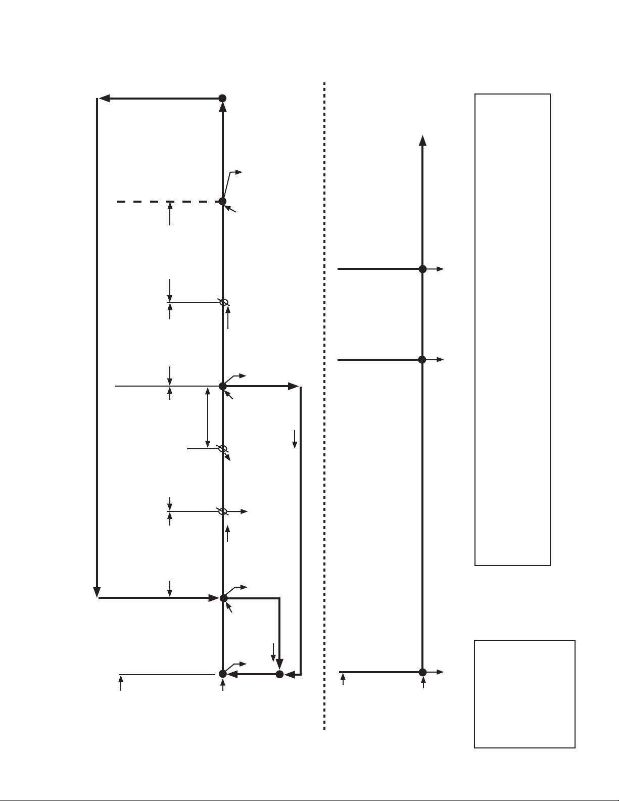
b) "G" Control Board: Auxiliary Code U-1 and Later
10th cycle (S4 dip
switch 5 & 6)
for 2 sec., then
reverses for 10/20
sec. (S4 dip switch
F/S in control
5-min. timer
in control
3 & 4)
Comp continues
F/S open or freeze
F/S closed
FMR continues
timer expires
Comp continues
HGV energized
FMR continues
PM energized
PM de-energizes for 2 sec.,
then reverses for 10/20 sec.
FM de-energized
FMS energized
LLV energized
HGV de-energized
LLV de-energized
3. Ice Level Lowered
2. Icemaker Off
4. Pump-Out Cycle
3. Freeze Cycle
•Factorysetforevery
•Minimumfreezetime:5min.
•Pumpmotorstops
(S4 dip switch 9 & 10)
•Maximumfreezetime:freezetimersetting
To 1 above
Ice level lowered. No ice
pressing against MBC actuator
paddle. Icemaker starts at
"1. 1-Minute Fill Cycle."
MBC closed
Green "BC CLOSED" LED on
Yellow "BC OPEN" LED off
All components
de-energized.
"G" Control Board Sequence Flow Chart
KM-901MAH, KM-901MWH, KM-901MRH/3
2. Harvest Cycle
50 sec. (S4 dip switch 7), whichever is shorter. DO
NOT ADJUST S4 dip switch 7 on this model.
•WVtime:6min.orthelengthofharvestminus0or
•Maximumharvesttime:20min.
Fill Cycle
1. 1-Minute
1 to 3-min. timer in control
(S4 dip switch 1 & 2)
Thermistor in
control
Harvest Pump
Timer
F/S check
0 or 50 sec.
PM energized
WV de-energized
F/S closed
F/S check
Thermistor temperature
reaches 48°F (9°C) (3.9 kΩ
or less). Harvest timer starts.
WV continues
Comp energized
FMR energized
HGV energized
F/S open
WV energized
F/S open
If F/S is open, compressor stops and cycle returns to 1-Minute Fill Cycle
1. Bin Full
Shutdown Delay:
•Fill Cycle–15 sec. after activation.
•Harvest Cycle–At the end of the harvest cycle, or up to 15 sec. into the
Yellow "BC OPEN" LED continues.
All components de-energized
Components Energized when the Control Switch is in the "WASH" Position
The "WASH" position on the control switch is used when cleaning and sanitizing the unit. When in the "WASH" position, power is
supplied to the pump motor. With the cleaning valve closed, the cleaner and sanitizer ow over the outside of the evaporator plate
assembly. With the cleaning valve open, the cleaner and sanitizer ow over both the outside and the inside of the evaporator plate
assembly.
Note: Close the cleaning valve after cleaning and sanitizing are complete, otherwise the unit will not restart when the control
switch is placed in the "ICE" position.
freeze cycle if activated at the end of the harvest cycle.
5-min. short cycle protection timer expires. Otherwise, at the end
of the next harvest cycle.
•Freeze Cycle–15 sec. after activation if activated at least 15 sec. before the
MBC open
Green "BC CLOSED" LED off
Yellow "BC OPEN" LED on
Cycle Steps
Initial startup
Shutdown
and Restart
begins here
after 5-sec.
delay
MBC Operation
Legend:
Comp–compressor
FM–fan motor
FMR–fan motor-remote
F/S–oat switch
HGV–hot gas valve
LLV–liquid line valve
MBC–mechanical bin control
PM–pump motor
WV–inlet water valve
25
Page 26

C. Control Board
•AHoshizakiexclusivesolid-statecontrolboardisemployedinKM-901MAH,
KM-901MWH, and KM-901MRH/3 Modular Crescent Cubers.
•Allmodelsarepretestedandfactoryset.
CAUTION
1. The control board is fragile; handle very carefully.
2. The control board contains integrated circuits, which are susceptible to
failure due to static discharge. It is especially important to touch the metal
part of the unit before handling or replacing the control board.
3. Do not touch the electronic devices on the control board or the back of the
control board.
4. Do not change wiring and connections. Do not misconnect K3, K4, and K5,
because the same connector is used for the thermistor, mechanical bin
control, and oat switch. K4 is not used on "E" control board models.
5. Always replace the whole control board assembly if it goes bad.
6. Do not short out power supply to test for voltage.
26
Page 27
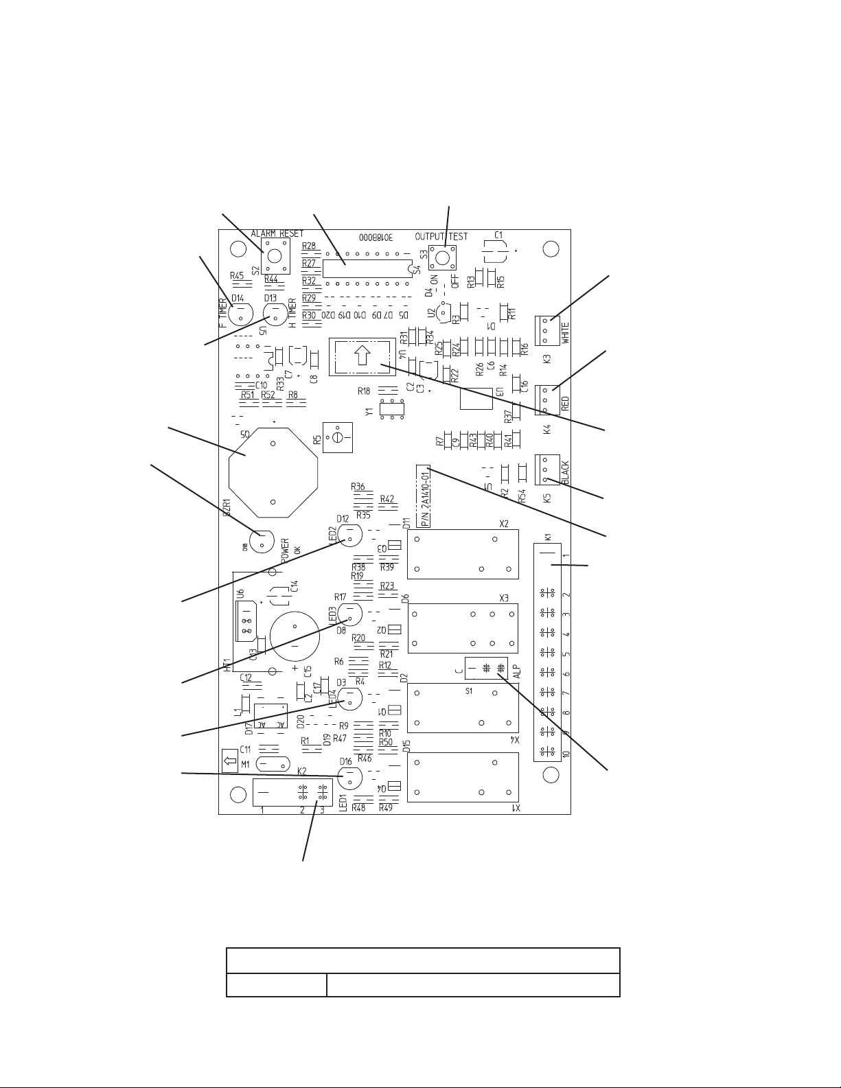
1. Control Board Layout
a) "E" Control Board: Auxiliary Code T-0, U-0
"E" Control Board
"ALARM RESET" Button
Freeze Timer LED
S4 Dip Switch
"OUTPUT TEST" Button
(used to test relays on control board)
WHITE K3 Connector
Harvest Control
(thermistor)
Harvest Timer LED
Alarm Buzzer
Power LED
(lights when
power is
supplied to the
control board)
Relay LEDs (4)
(indicate which
relays are energized
as listed below)
LED 2 (X2 Relay)
Hot Gas Valve (HGV)
Fan Motor (FM) (FM off
when LED on)
Liquid Line Valve (LLV)
LED 3 (X3 Relay)
Pump Motor (PM)
(on at pump-out only)
LED 4 (X4 Relay)
Inlet Water Valve (WV)
LED 1 (X1 Relay)
Compressor (Comp),
Fan Motor-Remote
(FMR)
RED K4 Connector
Mechanical Bin Control
(not used on units with
themostatic bin control)
Microprocessor
(control board revision
level indicated by last
2 digits on label)
BLACK K5 Connector
Float Switch
Part Number
K1 Ten-Pin Connector
Pins #1 through #10
#1, 9 Magnetic Contactor
#2 Hot Gas Valve (HGV)
#3 Fan Motor (FM),
Liquid Line Valve (LLV)
#4 Pump Motor (icemaking)
#5 Pump Motor (pump-out)
#6 Inlet Water Valve (WV)
#7, 10 Component Power
Supply
#8 Open
Switch for "C" control board
and "ALPINE" control board
(service control board only)
K2 Connector
Transformer
"E" Control Board
Part Number 2A1410-01 (factory); 2A1410-02 (service)
27
Page 28

b) "G" Control Board: Auxiliary Code U-1 and Later
"G" Control Board
Bin Control Switch
Closed LED (green)
(on continuously
in thermostatic bin
control application)
Bin Control Switch
Open LED (yellow)
(mechanical bin control
application only)
Part Number
Alarm Buzzer
Power LED (red)
(lights when
power is supplied
to the control board)
Relay LEDs (4)
(indicate which
relays are energized
as listed below)
LED 2 (X2 Relay)
Hot Gas Valve (HGV)
Fan Motor (FM)
(FM off when LED on)
Liquid Line Valve (LLV)
LED 3 (X3 Relay)
Pump Motor (PM)
(on at pump-out,
harvest (if applicable))
LED 4 (X4 Relay)
Inlet Water Valve (WV)
LED 1 (X1 Relay)
Compressor (Comp),
Fan Motor-Remote
(FMR)
"ALARM RESET" Button
S4 Dip
Switch
"OUTPUT TEST" Button
(used to test relays on control board)
WHITE K3 Connector
Harvest Control
(thermistor)
RED K4 Connector
Mechanical Bin Control or
K4 Jumper (thermostatic
bin control application)
S5 Dip Switch
BLACK K5 Connector
Float Switch
Label
(control board revision
level indicated on label
on side of relay)
K1 Ten-Pin Connector
Pins #1 through #10
#1, 9 Magnetic Contactor
#2 Hot Gas Valve (HGV)
#3 Fan Motor (FM),
Liquid Line Valve (LLV)
#4 Pump Motor (icemaking)
#5 Pump Motor (pump-out,
harvest (if applicable))
#6 Inlet Water Valve (WV)
#7, 10 Component Power
Supply
#8 Open
Switch for "C" control board
and "ALPINE" control board
(service control board only)
K2 Connector
Transformer
"G" Control Board
Part Number 2A3792-01
28
Page 29

2. Features
a) Maximum Water Supply Period - 6 minutes
"E" control board: The inlet water valve is open during harvest for 6 minutes or the length
of harvest, whichever is shorter.
"G" control board: The inlet water valve is open during harvest for 6 minutes or the
length of harvest minus 0 or 50 seconds (harvest pump timer (S4 dip switch 7)),
whichever is shorter. For details, see "II.C.3.e) Bin Control Selector/Harvest Pump Timer
(S4 dip switch 7)."
b) Harvest Backup Timer and Freeze Timer
The harvest backup timer shuts down the icemaker if, for two cycles in a row, the
harvest cycle takes more than 20 minutes to complete. The control board signals this
problem using 2 beeps every 3 seconds.
The freeze timer shuts down the icemaker if, for two cycles in a row, the freeze cycle
takes longer than the time specied to complete. The control board signals this
problem using 3 beeps every 3 seconds. The freeze timer is factory set using S4 dip
switch 9 &10. For details, see "II.C.3.g) Freeze Timer (S4 dip switch 9 & 10)."
The "ALARM RESET" button on the control board must be pressed with power on to
reset either of these safeties.
c) High Temperature Safety
The temperature of the suction line in the refrigeration circuit is limited by the high
temperature safety. This protects the unit from excessively high temperatures. If the
evaporator temperature reaches 127°F±7°F (53°C±4°C), the control board reads a
.8 kΩ signal from the thermistor and shuts down the icemaker.
The control board will signal this problem using 1 beep every 3 seconds. The "ALARM
RESET" button on the control board must be pressed with power on to reset the safety.
d) Low Water Safety
The control board checks the position of the oat switch at the end of the initial 1-minute
ll cycle and at the end of each harvest cycle. If the oat switch is in the up position
(electrical circuit closed), the control board changes to the next cycle. If the oat switch
is in the down position (electrical circuit open), the control board changes to additional
1-minute ll cycles until water enters the tank and closes the oat switch. When the oat
switch closes, the control board changes to the next cycle. The unit will not start without
adequate water in the tank. This serves as a low water safety to protect the water pump.
For water-cooled model, if the condenser water supply is shut off, the unit is protected by
the high-pressure switch.
e) High Voltage and Low Voltage Cut-outs
The maximum and minimum allowable supply voltages of this icemaker are limited by
the high voltage and low voltage cut-outs. If miswiring (especially on single phase 3 wire
models) causes excessive voltage (147Vac±5% or more), the high voltage cut-out shuts
down the circuit in 3 seconds and the icemaker automatically stops. The control board
will signal this problem using 7 beeps every 3 seconds.
The icemaker also automatically stops in cases of insufficient voltage (92Vac±5% or
less). The control board will signal this problem using 6 beeps every 3 seconds. When
the proper supply voltage is resumed, the icemaker automatically starts running again.
29
Page 30

f) LED Lights and Audible Alarm Safeties
(1) "E" Control Board: Auxiliary Code T-0, U-0
At startup, a 5-second delay occurs while the control board conducts an internal timer
check. A beep occurs when power is turned off. The red LED indicates proper control
voltage and remains on unless a control voltage problem occurs. The green LEDs
1 through 4 energize and sequence from initial startup as listed in the table below. Note
that the order of the LEDs from the outer edge of the control board is 1, 4, 3, 2.
For details, see "II.B. Sequence of Operation."
Sequence Step LED
1-Minute Fill Cycle 4 WV 1 minute
Harvest Cycle 1, 4, 2 Comp, FMR, WV,
Freeze Cycle 1 Comp, FM/FMR, PM,
Pump-Out Cycle 1, 4*, 3, 2 Comp, FMR, WV*,
Energized
Components
HGV
LLV
PM, HGV
Min. Max. Avg.
2 minutes 20 minutes 3 to 5 minutes
5 minutes freeze timer
10 seconds 20 seconds *pump-out timer setting
Time LEDs are On
30 to 35 minutes
setting
The built-in safeties shut down the unit and have alarms as listed below.
No. of Beeps
(every 3 sec.)
1 High Evaporator Temp.
(temperature > 127°F)
(53°C)
2 Harvest Backup Timer
(harvest > 20 min. for two cycles
in a row)
3 Freeze Timer
(freeze > freeze timer setting for
two cycles in a row)
To reset the above safeties, press the "ALARM RESET" button with the power supply on.
6 Low Voltage
(92Vac±5% or less)
7 High Voltage
(147Vac±5% or more)
Type of Alarm Notes
Check for harvest problem (stuck HGV or relay), hot
water entering unit, stuck HM, or shorted thermistor.
Orange "H TIMER" LED on.
Check for open thermistor, HGV not opening, TXV or
LLV leaking by, low charge, inefficient Comp, or WRV
leaking by.
Yellow "F TIMER" LED on.
Check for F/S stuck closed (up), WV leaking by, HGV
leaking by, PM not pumping, TXV not feeding properly,
LLV not opening, low charge, HM not bypassing, or
inefficient Comp.
Red LED turns off if voltage protection operates.
The control voltage safeties automatically reset when
voltage is corrected.
Legend: Comp–compressor; FM–fan motor; FMR–fan motor-remote;
F/S–oat switch; HGV–hot gas valve; HM–headmaster (C.P.R.); L LV –liquid
line valve; PM–pump motor; TXV–thermostatic expansion valve; WRV–water
regulating valve; WV–inlet water valve
30
Page 31

(2) "G" Control Board: Auxiliary Code U-1 and Later
At startup, a 5-second delay occurs while the control board conducts an internal timer
check. A beep occurs when the control switch is moved to the "ICE" position. The red
LED indicates proper control voltage and remains on unless a control voltage problem
occurs. The green LEDs 1 through 4 energize and sequence from initial startup as
listed in the table below. Note that the order of the LEDs from the outer edge of the
control board is 1, 4, 3, 2. For details, see "II.B. Sequence of Operation."
Sequence Step LED
1-Minute Fill Cycle 4 WV 1 minute
Harvest Cycle 1, 4, 2 Comp, FMR, WV, HGV 2 minutes 20 minutes 3 to 5 minutes
Harvest Pump Timer 1, 3, 2 Comp, FMR, PM, HGV 0 seconds 50 seconds harvest pump timer
Freeze Cycle 1 Comp, FM/FMR, PM,
LLV
Pump-Out Cycle 1, 4*, 3, 2 Comp, FMR, WV*, PM,
HGV
Energized
Components
Min. Max. Avg.
5 minutes freeze timer
10 seconds 20 seconds *pump-out timer
Time LEDs are On
setting
30 to 35 minutes
setting
setting
The built-in safeties shut down the unit and have alarms as listed below.
No. of Beeps
(every 3 sec.)
1 High Evaporator Temp.
(temperature > 127°F)
(53°C)
2 Harvest Backup Timer
(harvest > 20 min. for two cycles
in a row)
3 Freeze Timer
(freeze > freeze timer setting for
two cycles in a row)
To reset the above safeties, press the "ALARM RESET" button with the power supply on.
6 Low Voltage
(92Vac±5% or less)
7 High Voltage
(147Vac±5% or more)
Type of Alarm Notes
Check for harvest problem (stuck HGV or relay), hot
water entering unit, stuck HM, or shorted thermistor.
Check for open thermistor, HGV not opening, TXV or
LLV leaking by, low charge, inefficient Comp, or WRV
leaking by.
Check for F/S stuck closed (up), WV leaking by, HGV
leaking by, PM not pumping, TXV not feeding properly,
LLV not opening, low charge, HM not bypassing, or
inefficient Comp.
Red LED turns off if voltage protection operates.
The control voltage safeties automatically reset when
voltage is corrected.
Legend: Comp–compressor; FM–fan motor; FMR–fan motor-remote; F/S–oat switch;
HGV–hot gas valve; HM–headmaster (C.P.R.); LLV–liquid line valve; PM–pump
motor; TXV–thermostatic expansion valve; WRV–water regulating valve;
WV–inlet water valve
31
Page 32

3. Controls and Adjustments
CAUTION
Dip switches are factory set. Failure to maintain factory settings may adversely
affect performance and warranty coverage. For more information, contact
Hoshizaki Technical Support at 1-800-233-1940.
a) Default Dip Switch Settings
The dip switches are factory set to the following positions:
S4 Dip Switch
S4 Dip Switch No. 1 2 3 4 5 6 7 8 9 10
KM-901MAH ON OFF ON OFF ON ON OFF OFF OFF ON
KM-901MWH ON OFF ON OFF ON ON OFF OFF OFF ON
KM-901MRH/3 ON OFF ON OFF ON ON OFF OFF OFF ON
S5 Dip Switch
("G" Control Board: Auxiliary Code U-1 and Later)
S5 Dip Switch No. 1 2 3 4 5
KM-901MAH OFF OFF OFF OFF OFF
KM-901MWH OFF OFF OFF OFF OFF
KM-901MRH/3 OFF OFF OFF OFF OFF
Freeze Timer (9 & 10)
Factory Use (8)
Bin Control Selector (7) "E" Control Board
Harvest Pump Timer (7) "G" Control Board
(Do Not Adjust)
Pump-Out Frequency Control (5 & 6)
Pump-Out Timer (3 & 4)
Harvest Timer (1 & 2)
b) Harvest Timer (S4 dip switch 1 & 2)
The harvest timer when the thermistor reads 48°F (9°C) at the evaporator outlet and the
control board reads the thermistor's 3.9 kΩ signal. The harvest timer is factory set, and
generally no adjustment is required. However, a setting longer than the factory setting
may be advised in cases where the ush provided at harvest needs to be prolonged
for extra cleaning. Before changing this setting, contact Hoshizaki Technical Support at
1-800-233-1940 for recommendations. Keep in mind that setting the harvest timer to a
longer setting decreases 24-hour production.
Note that the pump-out timer (S1 dip switch 3 & 4) acts in place of the harvest timer
during cycles with a pump-out. For details, see "II.C.3.c) Pump-Out Timer (S1 dip
switch 3 & 4)."
S4 Dip Switch Setting
No. 1 No. 2
OFF OFF 60
ON OFF 90
OFF ON 120
ON ON 180
Time
(seconds)
32
Page 33

c) Pump-Out Timer (S4 dip switch 3 & 4)
When a pump-out is called for, the pump motor de-energizes after the preceding freeze
cycle. The pump motor energizes 2 seconds later in the reverse direction, taking water
from the bottom of the tank and forcing pressure against the check valve seat allowing
water to go through the check valve and down the drain. At the same time, water ows
through the small tube to power ush the oat switch. The pump motor drains the water
tank for the time determined by the pump-out timer. The pump-out timer also acts in
place of the harvest timer during cycles with a pump-out. The pump-out timer is factory
set, and generally no adjustment is required. However, where water quality is bad and
the icemaker needs a longer pump-out time, the pump-out timer can be adjusted. The
pump-out timer control can be set to pump-out for 10 or 20 seconds.
S4 Dip Switch Setting Time (seconds)
OFF OFF 10 150 Closed
ON OFF 10 180 Closed
OFF ON 10 120 Open
ON ON 20 180 Closed
Inlet
Water
ValveNo. 3 No. 4 T1 T2
T1: Time to drain the water tank
T2: Harvest timer at pump-out
d) Pump-Out Frequency Control (S4 dip switch 5 & 6)
The pump-out frequency control is factory set to drain the water tank every 10 cycles,
and generally no adjustment is required. However, where water quality is bad and the
icemaker needs a pump-out more often, the pump-out frequency can be adjusted. The
pump-out frequency control can be set to have a pump-out occur every cycle, or every
2, 5, or 10 cycles.
Timing of the rst pump-out is dependent on the control board. "E" control board rst
pump-out is after the rst freeze cycle. "G" control board rst pump-out is dependent on
S4 dip switch 5 & 6. See the table below.
"E" & "G" Control Board Settings 1st Pump-Out
S4 Dip Switch Setting
No. 5 No. 6
OFF OFF Every cycle After 1st freeze cycle After 2nd freeze cycle
ON OFF Every 2 cycles After 3rd freeze cycle
OFF ON Every 5 cycles After 6th freeze cycle
ON ON Every 10 cycles After 11th freeze cycle
Pump-Out
Frequency
"E" Control Board "G" Control Board
33
Page 34

e) Bin Control Selector/Harvest Pump Timer (S4 dip switch 7)
Depending on the control board, S4 dip switch 7 is either a bin control selector or harvest
pump timer.
CAUTION
Do not adjust. This dip switch must be left in the factory default position or this
unit will not operate correctly.
(1) Bin Control Selector, "E" Control Board: Auxiliary Code T-0, U-0
Factory set for proper operation. Do not adjust. When set to the on position on a unit
with a thermostatic bin control, a 5-beep alarm sounds (open circuit) and the unit does
not operate.
"E" Control Board
S4 Dip Switch Setting
No. 7
ON Mechanical
OFF Thermostatic
(2) Harvest Pump Timer, "G" Control Board: Auxiliary Code U-1 and Later
Factory set for proper operation. Do not adjust. Depending on the harvest pump timer
setting, the pump motor energizes and runs the last 0 or 50 seconds of harvest. The
water valve is energized during harvest for a maximum of 6 minutes or the length
of harvest minus 0 or 50 seconds (determined by the harvest pump timer setting),
whichever is shorter. CAUTION! Do not adjust S4 dip switch 7 out of the factory
default position on this model. This dip switch must be left in the factory default
position or this unit will not operate correctly.
Bin Control
"G" Control Board
S4 Dip Switch Setting
No. 7
ON 50
OFF 0
Pump Motor
Time (seconds)
f) Factory Use (S4 dip switch 8)
Factory set for proper operation. Do not adjust. This must be left in the factory default
position.
34
Page 35

g) Freeze Timer (S4 dip switch 9 & 10)
CAUTION
Adjust to proper specication, or the unit may not operate correctly.
The freeze timer setting determines the maximum allowed freeze time to prevent
possible freeze-up issues. Upon termination of the freeze timer, the control board
initiates the harvest cycle. After 2 consecutive freeze timer terminations, the control
board shuts down the icemaker. In this case, see "IV.F.3. Low Ice Production" for
possible solutions. The freeze timer is factory set, and generally no adjustment
is required. Before changing this setting, contact Hoshizaki Technical Support at
1-800-233-1940 for recommendations.
S4 Dip Switch Setting
No. 9 No. 10
OFF OFF 60
OFF ON 50
ON OFF 70
ON ON 60
Time
(minutes)
h) Float Switch Control (S5 dip switch 1): "G" Control Board
CAUTION
Do not adjust. This must be left in the factory default position or the unit will not
operate correctly.
Factory set. S5 dip switch 1 allows for single or double oat switch applications. The
KM-901MAH, KM-901MWH, and KM-901MRH/3 use a single oat switch.
i) Rell Counter (S5 dip switch 2 through 5): "G" Control Board
CAUTION
Do not adjust. These must be left in the factory default position or the unit will
not operate correctly.
Factory set. S5 dip switch 2 through 5 allows for rells during the freeze cycle. The
KM-901MAH, KM901MWH, and KM-901MRH/3 do not rell.
35
Page 36

D. Bin Control
1. Thermostatic Bin Control: Auxiliary Code T-0, U-0
CAUTION
When the ambient temperature is below 45°F (7°C), the thermostatic bin
control switch opens and shuts down the icemaker even if the ice storage bin
is empty. When the thermostat is set in the prohibited range, the icemaker
operates continuously even if the ice storage bin is lled with ice. Setting in the
prohibited range may result in severe damage to the icemaker.
The thermostatic bin control switch is a temperature controlled switch used to control
the level of ice in the bin. It is in line with the power supply to the control switch.
The thermostatic bin control switch shuts down the unit within 10 seconds when ice
contacts the thermostatic bulb, regardless of the cycle at activation. The thermostatic
bin control is factory set, and generally no adjustment is required. However,
adjustment may be needed in some conditions, particularly at higher altitude
locations. For further details, see "IV.C.1. Thermostatic Bin Control Check."
2. Mechanical Bin Control: Auxiliary Code U-1 and Later
The mechanical bin control is a lever-actuated bin control switch used to control the
level of ice in the bin. The mechanical bin control connects to the control board RED
K4 connector. When the actuator paddle is not engaged (mechanical bin control
switch closed; control board green "BC CLOSED" LED on), the unit produces ice.
When the actuator paddle is engaged (mechanical bin control switch open; control
board yellow "BC OPEN" LED on), the unit shuts down as outlined in the table below.
Cycle at
Mechanical Bin
Control Activation
Fill Cycle 15 seconds after activation.
Harvest Cycle At the end of the harvest cycle, or up to 15 seconds into the freeze cycle if
Freeze Cycle 15 seconds after activation if activated at least 15 seconds before the 5-minute
Shutdown
activated at the end of the harvest cycle.
short cycle protection timer expires. Otherwise, at the end of the next harvest
cycle.
E. Float Switch
The oat switch is used to determine that there is sufficient water in the tank after
the 1-minute ll cycle and after each harvest cycle. The oat switch is also used to
determine that the appropriate volume of water has been converted into ice before
switching out of the freeze cycle. No adjustment is required.
F. Thermistor
The thermistor is used as a harvest control sensor. The thermistor's resistance varies
depending on the suction line temperature. The control board monitors the resistance to
start the harvest timer. No adjustment is required.
G. Control Switch
The control switch has three positions: "OFF" for power off, "ICE" for icemaking, and
"WASH" to activate the water pump when cleaning and sanitizing.
36
Page 37

III. Technical Information
A. Water Circuit and Refrigeration Circuit
1. KM-901MAH (air-cooled)
Spray Tubes
Water Supply
Cleaning Valve
Inlet Water Valve
Float Switch
Drain
Water
Tank
Thermistor
Water Pump
Pump-Out
Freeze
Condenser
Evaporator
Fan
Drier
Suction Line
Access Valve
Compressor
High Pressure
Switch
Strainer
Hot Gas
Val ve
Check
Valves
Access
Val ve
Discharge Line
Refrigeration Circuit
Water Circuit
Expansion Valves
Check Valve
37
Page 38

2. KM-901MWH (water-cooled)
Water
Regulating
Val ve
Water Supply
Cleaning Valve
Inlet Water Valve
Float Switch
Drain
Spray Tubes
Water
Tank
Thermistor
Water Pump
Pump-Out
Freeze
Evaporator
Condenser
Drier
Suction Line
Access Valve
Compressor
Drain
Water Supply
High Pressure
Switch
Strainer
Hot Gas
Val ve
Check
Valves
Access
Val ve
Discharge Line
Refrigeration Circuit
Water Circuit
Expansion Valves
Check Valve
38
Page 39

3. KM-901MRH/3 (remote air-cooled)
Condenser
Spray Tubes
Inlet Water Valve
Fan
Headmaster
(C.P.R.)
Access
Val ve
Water Supply
Cleaning Valve
Float Switch
Drain
Water
Tank
Thermistor
Water Pump
Pump-Out
Freeze
Receiver
Tank
Evaporator
Liquid Line
Val ve
Suction Line
Access Valve
Compressor
Drier
High Pressure
Switch
Strainer
Hot Gas
Val ve
Check
Valves
Access
Val ve
Discharge Line
Refrigeration Circuit
Water Circuit
Expansion Valves
Check Valve
39
Page 40

B. Wiring Diagrams
1. Thermostatic Bin Control: Auxiliary Code T-0, U-0
a) KM-901MAH (air-cooled) and KM-901MWH (water-cooled)
Thermostatic Bin Control: Auxiliary Code T-0, U-0
Transformer Output
10.5V at 115V
PSIG
0
21
*
PSIG 384±
0
21
* High Pressure Switch
Air-Cooled Model Water-Cooled Model
Cut-in 327±21 PSIG 284±21 PSIG
Cut-out 412±
40
Page 41

b) KM-901MRH (remote air-cooled)
Thermostatic Bin Control: Auxiliary Code T-0, U-0
Transformer Output
10.5V at 115V
*
PSIG
0
21
* High Pressure Switch
Cut-out 412±
Cut-in 327±21 PSIG
41
Page 42

c) KM-901MRH3 (remote air-cooled)
Thermostatic Bin Control: Auxiliary Code T-0, U-0
Transformer Output
10.5V at 115V
* High Pressure Switch
PSIG
0
21
Cut-out 412±
Cut-in 327±21 PSIG
*
42
Page 43

2. Mechanical Bin Control: Auxiliary Code U-1 and Later
a) KM-901MAH (air-cooled) and KM-901MWH (water-cooled)
Mechanical Bin Control: Auxiliary Code U-1 and Later
Transformer Output
10.5V at 115V
PSIG
21
*
PSIG 384±
0 0
21
* High Pressure Switch
Air-Cooled Model Water-Cooled Model
Cut-in 327±21 PSIG 284±21 PSIG
Cut-out 412±
43
Page 44

b) KM-901MRH (remote air-cooled)
Mechanical Bin Control: Auxiliary Code U-1 and Later
Transformer Output
10.5V at 115V
PSIG
0
*
21
* High Pressure Switch
Cut-out 412±
Cut-in 327±21 PSIG
44
Page 45

c) KM-901MRH3 (remote air-cooled)
Mechanical Bin Control: Auxiliary Code U-1 and Later
Transformer Output
10.5V at 115V
*
* High Pressure Switch
PSIG
0
21
Cut-in 327±21 PSIG
Cut-out 412±
45
Page 46

C. Performance Data
1. KM-901MAH (air-cooled)
APPROXIMATE ICE
PRODUCTION PER 24 HR.
lbs./day kg./day 100/38 826 375 721 327 646 293
APPROXIMATE ELECTRIC
CONSUMPTION
watts 100/38
APPROXIMATE WATER
CONSUMPTION PER 24 HR.
gal./day m3/day 100/38 175 0.66 139 0.52 103 0.39
FREEZING CYCLE TIME
min. 100/38
HARVEST CYCLE TIME
min. 100/38
HEAD PRESSURE
AMBIENT TEMP.
(ºF/ºC) 50/10 70/21 90/32
70/21 874 396 832 378 785 356
80/27 842 382 778 353 736 334
90/32 832 378 732 332 687 312
70/21
80/27
90/32
70/21 240 0.91
80/27 219 0.83 175 0.66 158 0.60
90/32 212 0.80 143 0.54 123 0.46
70/21
80/27
90/32
70/21
80/27
90/32
70/21 219 15.4
80/27 234 16.4 263 18.5 284 20.0
90/32 238 16.7 284 20.0 306 21.5
1600
1625
1632
1631
19
20
20
21
4.3
4.0
3.9 2.6
3.3
WATER TEMP. (ºF/ºC)
1632
1675
1710
1715
212 0.80 187 0.71
20
22
24
24
3.9
3.3
2.8
2.7
238 16.7 261 18.3
1658
1691
1731
1750
3.6
3.1
2.4
22
24
26
27
PSIG kg/cm2G 100/38 242 17.0 289 20.3 327 23.0
SUCTION PRESSURE
PSIG kg/cm2G 100/38 38 2.7 42 3.0 50 3.5
TOTAL HEAT OF REJECTION FROM CONDENSER
70/21 35 2.5 37 2.6 41 2.9
80/27 36 2.6 39 2.7 44 3.1
90/32 37 2.6 41 2.9 46 3.2
15,400 BTU/h [AT 90ºF (32ºC) / WT 70ºF (21ºC)]
Note:
1. Pressure data is recorded at 5 minutes into freeze cycle. The data not in bold
should be used for reference only.
2. We reserve the right to make changes in specications and design without prior
notice.
46
Page 47

2. KM-901MWH (water-cooled)
APPROXIMATE ICE
PRODUCTION PER 24 HR.
lbs./day kg./day 100/38 878 398 825 374 751 341
APPROXIMATE ELECTRIC
CONSUMPTION
watts 100/38
APPROXIMATE WATER
CONSUMPTION PER 24 HR.
gal./day m3/day 100/38 1360 5.15 1493 5.65 2559 9.69
FREEZING CYCLE TIME
min. 100/38
HARVEST CYCLE TIME
min. 100/38
HEAD PRESSURE
AMBIENT TEMP.
(ºF/ºC)
70/21 912 414 889 403 849 385
80/27 895 406 860 390 815 370
90/32 889 403 835 379 791 359
70/21
80/27
90/32
70/21 876 3.32
80/27 981 3.71 1194 4.52 1893 7.17
90/32 1013 3.84 1344 5.09 1977 7.48
70/21
80/27
90/32
70/21
80/27
90/32
70/21 227 16.0
80/27 229 16.1 233 16.4 247 17.4
90/32 230 16.1 236 16.6 249 17.5
50/10 70/21 90/32
1480
1500
1506
1505
18
19
19
19
4.1
3.9
3.8 2.93.1
3.4
WATER TEMP. (ºF/ºC)
1506
1541
1570
1574
1013 3.84 1530 5.79
19
19
20
20
3.8
3.4
3.0
230 16.1 240 16.9
1527
1553
1586
1600
20
21
21
22
3.6
3.3
2.7
PSIG kg/cm2G 100/38 234 16.4 239 16.8 260 18.3
SUCTION PRESSURE
PSIG kg/cm2G 100/38 36 2.5 38 2.7 45 3.2
TOTAL HEAT OF REJECTION FROM CONDENSER
TOTAL HEAT OF REJECTION FROM COMPRESSOR 2,100 BTU/h [AT 90ºF (32ºC) / WT 70ºF (21ºC)]
WATER FLOW FOR CONDENSER 100 gal./h [AT 100ºF (38ºC) / WT 90ºF (32ºC)]
PRESSURE DROP OF COOLING WATER LINE less than 10 PSIG
70/21 33 2.3 34 2.4 38 2.6
80/27 34 2.4 36 2.5 40 2.8
90/32 34 2.4 37 2.6 41 2.9
13,500 BTU/h [AT 90ºF (32ºC) / WT 70ºF (21ºC)]
Note:
1. Pressure data is recorded at 5 minutes into freeze cycle. The data not in bold
should be used for reference only.
2. We reserve the right to make changes in specications and design without prior
notice.
47
Page 48

3. KM-901MRH (remote air-cooled)
APPROXIMATE ICE
PRODUCTION PER 24 HR.
lbs./day kg./day 100/38 843 382 771 350 668 303
APPROXIMATE ELECTRIC
CONSUMPTION
watts 100/38
APPROXIMATE WATER
CONSUMPTION PER 24 HR.
gal./day m3/day 100/38 182 0.69 147 0.56 112 0.42
FREEZING CYCLE TIME
min. 100/38
HARVEST CYCLE TIME
min. 100/38
HEAD PRESSURE
AMBIENT TEMP.
(ºF/ºC)
70/21 889 403 859 389 803 364
80/27 866 393 818 371 755 343
90/32 859 389 785 356 724 328
70/21
80/27
90/32
70/21 246 0.93
80/27 225 0.85 182 0.69 165 0.63
90/32 219 0.83 152 0.57 131 0.50
70/21
80/27
90/32
70/21
80/27
90/32
70/21 208 14.6
80/27 224 15.7 256 18.0 277 19.5
90/32 229 16.1 279 19.6 301 21.2
50/10 70/21 90/32
1590
1630
1643
1630
18
19
20
20
4.3
4.0
3.9 2.7
3.4
WATER TEMP. (ºF/ºC)
1643
1712
1770
1771
219 0.83 194 0.74
20
21
22
23
3.9
3.4
2.9
2.8
229 16.1 252 17.7
1664
1705
1775
1780
3.6
3.2
2.4
21
23
24
26
PSIG kg/cm2G 100/38 232 16.3 284 20.0 322 22.6
SUCTION PRESSURE
PSIG kg/cm2G 100/38 38 2.7 44 3.1 51 3.6
TOTAL HEAT OF REJECTION FROM CONDENSER
TOTAL HEAT OF REJECTION FROM COMPRESSOR
CONDENSER VOLUME 121 CU. IN (URC-9F)
70/21 35 2.5 37 2.6 41 2.9
80/27 37 2.6 40 2.8 45 3.1
90/32 37 2.6 43 3.0 47 3.3
14,000 BTU/h [AT 90ºF (32ºC) / WT 70ºF (21ºC)]
2,200 BTU/h [AT 90ºF (32ºC) / WT 70ºF (21ºC)]
Note:
1. Pressure data is recorded at 5 minutes into freeze cycle. The data not in bold
should be used for reference only.
2. We reserve the right to make changes in specications and design without prior
notice.
48
Page 49

4. KM-901MRH3 (remote air-cooled)
APPROXIMATE ICE
PRODUCTION PER 24 HR.
lbs./day kg./day 100/38 855 388 800 363 689 313
APPROXIMATE ELECTRIC
CONSUMPTION
watts 100/38
APPROXIMATE WATER
CONSUMPTION PER 24 HR.
gal./day m3/day 100/38 185 0.70 144 0.54 123 0.46
FREEZING CYCLE TIME
min. 100/38
HARVEST CYCLE TIME
min. 100/38
HEAD PRESSURE
AMBIENT TEMP.
(ºF/ºC)
70/21 899 408 874 397 817 371
80/27 880 399 842 382 772 350
90/32 874 397 815 370 749 340
70/21
80/27
90/32
70/21 254 0.96
80/27 230 0.87 181 0.69 174 0.66
90/32 222 0.84 147 0.56 134 0.51
70/21
80/27
90/32
70/21
80/27
90/32
70/21 206 14.5
80/27 220 15.5 249 17.5 272 19.1
90/32 225 15.8 270 19.0 293 20.6
50/10 70/21 90/32
1670
1706
1717
1716
19
20
20
20
4.4
4.0
3.9 2.6
3.4
WATER TEMP. (ºF/ºC)
1717
1779
1830
1837
222 0.84 203 0.77
20
21
22
23
3.9
3.3
2.8
2.7
225 15.8 248 17.5
1755
1803
1861
1890
21
23
24
26
3.6
3.2
2.4
PSIG kg/cm2G 100/38 229 16.1 275 19.4 315 22.1
SUCTION PRESSURE
PSIG kg/cm2G 100/38 39 2.7 43 3.0 49 3.4
TOTAL HEAT OF REJECTION FROM CONDENSER
TOTAL HEAT OF REJECTION FROM COMPRESSOR
CONDENSER VOLUME 121 CU. IN (URC-9F)
70/21 36 2.5 38 2.7 41 2.9
80/27 37 2.6 40 2.8 44 3.1
90/32 38 2.7 42 3.0 46 3.2
14,100 BTU/h [AT 90ºF (32ºC) / WT 70ºF (21ºC)]
2,200 BTU/h [AT 90ºF (32ºC) / WT 70ºF (21ºC)]
Note:
1. Pressure data is recorded at 5 minutes into freeze cycle. The data not in bold
should be used for reference only.
2. We reserve the right to make changes in specications and design without prior
notice.
49
Page 50

IV. Service Diagnosis
WARNING
1. This unit should be diagnosed and repaired only by qualied service
personnel to reduce the risk of death, electric shock, serious injury, or re.
2. Risk of electric shock. Use extreme caution and exercise safe electrical
practices.
3. Moving parts (e.g., fan blade) can crush and cut. Keep hands clear.
4. CHOKING HAZARD: Ensure all components, fasteners, and thumbscrews
are securely in place after the unit is serviced. Make sure that none have
fallen into the storage bin.
5. Make sure all food zones in the icemaker and storage bin are clean after
the unit is serviced. For cleaning procedures, see "VI. Cleaning and
Maintenance."
A. Diagnostic Procedure
The diagnostic procedure is basically a sequence check which can be used at unit
startup or for system diagnosis. This procedure allows you to diagnose electrical system
and component failures. Before conducting the diagnostic procedure, check for correct
installation, proper voltage per unit nameplate, and adequate water supply. Check
CB using the steps in "IV.B. Control Board Check." Check the dip switch settings to
assure that S4 dip switch 3, 4, 7, 8, 9, & 10 and S5 dip switch 1 through 5 ("G" CB) are
in the factory default position. S4 dip switch 1, 2, 5, & 6 are cleaning adjustments and
the settings are exible. For factory default settings, see "II.C.3.a) Default Dip Switch
Settings." As you go through the procedure, check to assure the components energize
and de-energize correctly. If not, those components and controls are suspect.
1) Turn off the power supply, then access the control box. Clear any ice from TBC or
MBC.
2) Turn on the power supply, then move the control switch to the "ICE" position. A
5-second delay occurs. The red "POWER OK" LED on CB comes on. On "G" CB,
the green "BC CLOSED" LED also comes on. If the yellow "BC OPEN" LED is on
(indicating a full bin), check MBC. See "IV.C.2.a) Mechanical Bin Control Check."
WARNING
1. Risk of electric shock. Use extreme caution and exercise safe electrical
practices.
2. Moving parts (e.g., fan blade) can crush and cut. Keep hands clear.
50
Page 51

3) 1-Minute Fill Cycle – LED 4 is on. WV energizes. After 1 minute, CB checks for a
closed F/S. If F/S is closed, the harvest cycle begins. If closed, continue to step 4. If
open, WV remains energized through additional 1-minute ll cycles until water lls the
tank and closes F/S (low water safety). Diagnosis: If WV does not open, check the
supply voltage at WV terminals, check continuity on the coil, conrm the screen or
external lter is not plugged (no water ow). If unit fails to start harvest, check for open
F/S or bad 1-minute timer in CB. See "IV.D. Float Switch Check and Cleaning" and "IV.
B. Control Board Check."
4) Initial Harvest Cycle – LEDs 1, 4, and 2 are on. WV remains energized, Comp, FMR,
HGV energize. CB monitors the warming of the evaporator via the thermistor located
on the suction line. When the thermistor reaches 48°F (9°C), CB reads a 3.9 kΩ signal
from the thermistor and turns harvest termination over to the harvest timer (S4 dip
switch 1 & 2). The harvest timer has settings of 60, 90, 120, and 180 seconds. For
details, see "II.C.3.b) Harvest Timer (S4 dip switch 1 & 2)." When the harvest timer
expires, the harvest cycle is complete. CB checks the position of F/S and proceeds to
the next cycle if it is closed or calls for a 1-minute ll cycle if it is open. The minimum
total time allowed by CB for a complete harvest cycle is 2 minutes.
"E" CB: WV is energized during harvest for a maximum of 6 minutes or the length of
harvest, whichever is shorter.
"G" CB: WV is energized during harvest for a maximum of 6 minutes or the length
of harvest minus 0 or 50 seconds (harvest pump timer (S4 dip switch 7)),
whichever is shorter. LED 4 goes off when WV de-energizes. LED 3 comes
on and PM energizes and runs for the last 0 or 50 seconds of harvest
depending on S4 dip switch 7 setting. CAUTION! Do not adjust S4 dip
switch 7 out of the factory default position on this model. This dip
switch must be left in the factory default position or this unit will not
operate correctly. For details, see "II.C.3.e) Bin Control Selector/Harvest
Pump Timer (S4 Dip Switch 7)."
Diagnosis: Check if Comp is running, HGV and WV still energized. Average harvest
cycle at factory setting is 2 to 3 minutes. How long does initial harvest last? 1.5 minutes
after initial harvest begins, touch Comp discharge line. Is it hot? If not, check refrigerant
pressures and Comp operation. If it is hot, touch the inlet line to the evaporator. Is it
hot? If it is hot and the freeze cycle is not starting, check the harvest timer adjustment
(S4 dip switch 1 & 2), the thermistor for open circuit, the discharge line temperature,
Comp efficiency, and if HGV is fully open. For a thermistor check, see "IV.E. Thermistor
Check." If 1-minute ll cycle starts after harvest, check that F/S is clean and operating
properly, see "IV.D. Float Switch Check and Cleaning." Make sure PM does not come
on last 50 seconds of harvest. For details, see "II.C.3.e) Bin Control Selector/Harvest
Pump Timer (S4 Dip Switch 7)."
51
Page 52

5) Freeze Cycle – LED 1 is on. Comp and FMR remain energized, PM, LLV, and
FM energize. WV and HGV de-energize. The unit is held in freeze by a 5-minute
short cycle protection timer (CB will not accept a signal from F/S). After the
5-minute short cycle protection timer expires, CB turns freeze termination over to
F/S. Diagnosis: During the rst 5 minutes of freeze, conrm that the evaporator
temperature drops. After 5 minutes in freeze, disconnect black F/S connector from
CB BLACK K5 connector. If the evaporator is not cold, check to see if HGV is still
open or if TXV is not opening properly, if WV is continuing to ll the reservoir, if there
are improper unit pressures, an inoperative Comp, or an inoperative HM. The unit
should switch out of the freeze cycle ("G" CB - 15 second delay after F/S opens before
terminating the freeze cycle). If the unit switches out of freeze with F/S removed, but
would previously not switch out of freeze with F/S connected (long freeze - 3 beep
alarm), F/S may be sticking. To check and clean F/S, see "IV.D. Float Switch Check
and Cleaning." If the unit remains in freeze (longer than 15 seconds on "G" CB)
after disconnecting the black F/S connector, replace CB. See "V.P. Removal and
Replacement of Control Board."
Note: Normal freeze cycle will last 20 to 40 minutes depending on model and
conditions. Cycle times and pressures should follow performance data provided
in this manual. See "III.C. Performance Data."
6) Pump-Out Cycle – (10/20 second pump-out) – LEDs 1, 3, and 2 are on. LED 4 is
on when S4 dip switch 3 & 4 are set to 3 off and 4 on. Comp and FMR remain
energized, HGV energizes. WV energizes if S4 dip switch 3 off and 4 on. LLV and
FM de-energize. PM stops for 2 seconds, then reverses for 10/20 seconds depending
on pump-out timer S4 dip switch 3 & 4 setting. When the pump-out timer expires, the
pump-out is complete. The pump-out frequency control is factory set for every 10th
cycle, and generally no adjustment is required. However, where water quality is bad
and the icemaker needs a pump-out more often, the pump-out frequency can be
adjusted. The pump-out frequency control (S4 dip switch 5 & 6) can be set to have
a pump-out occur every cycle, or every 2, 5, or 10 cycles. For details, see "II.C.3.d)
Pump-Out Frequency Control (S4 dip switch 5 & 6)."
Timing of the rst pump-out is dependent on CB. "E" CB rst pump-out is after the rst
freeze cycle. "G" CB rst pump-out is determined by S4 dip switch 5 & 6. See the table
below.
"E" & "G" Control Board Settings 1st Pump-Out
S4 Dip Switch Setting
No. 5 No. 6
OFF OFF Every cycle After 1st freeze cycle After 2nd freeze cycle
ON OFF Every 2 cycles After 3rd freeze cycle
OFF ON Every 5 cycles After 6th freeze cycle
ON ON Every 10 cycles After 11th freeze cycle
Pump-Out
Frequency
"E" Control Board "G" Control Board
Diagnosis: If PM does not reverse, check to see if S4 and S5 dip switch settings are in
the factory default position. Check PM circuit and capacitor, check #5 pin (DBu wire) on
CB K1 ten-pin connector for voltage. If water does not pump out, check and clean the
check valve assembly and tubing.
52
Page 53

7) Normal Harvest Cycle – same as the initial harvest cycle – See "IV.A.4) Initial Harvest
Cycle."
8) Shutdown
a) Thermostatic Bin Control: Auxiliary Code T-0, U-0
When the unit is running hold ice in contact with the thermostatic bulb, TBC
switch opens within 10 seconds, shutting down the unit. TBC is factory set, and
generally no adjustment is required. However, adjustment may be needed in
some conditions, particularly at higher altitude locations. CAUTION! Do not
adjust S4 dip switch 7 out of the factory default position on this model.
This dip switch must be left in the factory default position or this unit
will not operate correctly. Diagnosis: See "IV.C.1. Thermostatic Bin Control
Check."
b) Mechanical Bin Control: Auxiliary Code U-1 and Later
See "IV.C.2.a) Mechanical Bin Control Check."
Legend: CB–control board; Comp–compressor; FM–fan motor; FMR–fan motor-remote;
F/S–oat switch; HGV–hot gas valve; HM–headmaster (C.P.R.); L LV –liquid line
valve; MBC–mechanical bin control; PM–pump motor; TBC–thermostatic bin
control; TXV–thermostatic expansion valve; WV–inlet water valve
B. Control Board Check
Before replacing a control board that does not show a visible defect and that you
suspect is bad, always conduct the following check procedure. This procedure will help
you verify your diagnosis.
Alarm Reset: If the control board is in alarm (beeping), press the "ALARM RESET"
button on the control board with power on. Once reset, the unit starts at
the 1-minute ll cycle. For audible alarm information, see "II.C.2.f) LED
Lights and Audible Alarm Safeties."
1) Check the dip switch settings to assure that S4 dip switch 3, 4, 7, 8, 9, & 10 and
S5 dip switch 1 through 5 ("G" control board) are in the factory default position. S4 dip
switch 1, 2, 5, & 6 are cleaning adjustments and the settings are exible. For factory
default settings, see "II.C.3.a) Default Dip Switch Settings."
2) Move the control switch to the "ICE" position. If the red "POWER OK" LED is on, the
control voltage is good. If the "POWER OK" LED is off, check the control transformer
secondary circuit. The control transformer secondary circuit includes the cleaning valve
interlock switch. Make sure the interlock switch is closed; otherwise, no control voltage
is supplied to the K2 connector. Transformer output is 10.5V at 115V primary input. If
the secondary circuit has proper voltage and the red LED is off, the control board is
bad and should be replaced. See "V.P. Removal and Replacement of Control Board."
If the secondary circuit does not have proper voltage, check the control transformer
primary circuit. Check for 115V at the control board K1 ten-pin connector. Check the
#10 pin (BR wire) to a white neutral wire for 115V. Always choose a white neutral wire
to establish a good neutral connection when checking voltages. For additional checks,
see "IV.F.1.[1] The icemaker will not start."
53
Page 54

3) The "OUTPUT TEST" button provides a relay sequence test. Make sure the control
switch is in the "ICE" position, then press the "OUTPUT TEST" button. For the correct
lighting sequence, see the table below. Note that the order of the LEDs from the outer
edge of the control board is 1, 4, 3, 2. Components (e.g., compressor) cycle during the
test.
Control
Board
"E" 2, 3, 4, 1
"G" 1, 4, 3, 2
Correct LED
Lighting Sequence
Following the test, the icemaker resumes operation. If the LEDs do not light as
described above, the control board is bad and should be replaced. See "V.P. Removal
and Replacement of Control Board."
4) To verify voltage output from the control board to the components, slide the control
board K1 ten-pin connector out far enough to allow multimeter lead contact. With the
unit in the cycle to be tested, check output voltage from the corresponding pin on the
control board K1 ten-pin connector to ground. If output voltage is not found and the
appropriate LED is on, the control board is bad and should be replaced. See "V.P.
Removal and Replacement of Control Board."
C. Bin Control Check
1. Thermostatic Bin Control Check: Auxiliary Code T-0, U-0
To check the thermostatic bin control, follow the steps below.
CAUTION
When the ambient temperature is below 45°F (7°C), the thermostatic bin
control switch opens and shuts down the icemaker even if the ice storage bin
is empty. When the thermostat is set in the prohibited range, the icemaker
operates continuously even if the ice storage bin is lled with ice. Setting in the
prohibited range may result in severe damage to the icemaker.
The thermostatic bin control is factory set, and generally no adjustment is required.
However, adjustment may be needed in some conditions, particularly at higher altitude
locations.
1) Turn off the power supply.
2) Remove the front panel, then remove the control box cover.
3) Disconnect the thermostatic bin control wires from the thermostatic bin control switch.
4) Clear any ice away from the thermostatic bulb, then hold your hand around the
thermostatic bulb to warm it up.
5) Check for continuity across the thermostatic bin control switch. If closed, continue to
step 6. If open, adjust or replace the thermostatic bin control.
6) With the multimeter test leads still in place, hold ice on the thermostatic bulb to lower
the temperature. Within 10 seconds, the thermostatic bin control switch should open
(no continuity). If it remains closed, adjust or replace the thermostatic bin control.
54
Page 55

2. Mechanical Bin Control Check and Cleaning: Auxiliary Code U-1 and Later
a) Mechanical Bin Control Check
To check the mechanical bin control switch, follow the steps below.
1) Turn off the power supply.
2) Remove the front panel, then move the control switch to the "OFF" position.
3) Remove the control box cover, then clear any ice away from the mechanical bin control.
4) Disconnect the red connector from the control board RED K4 connector.
5) Check for continuity across the wires of the red connector. See Fig. 1. When the
actuator paddle is not engaged, the mechanical bin control switch is closed. If open,
check that the white harness connector is secured to the mechanical bin control switch
connector and that the actuator paddle is not sticking. Clean if necessary. See "IV.
C.2.b) Mechanical Bin Control Cleaning." See Fig. 1. If the mechanical bin control
switch still reads open, replace the mechanical bin control.
6) Press the actuator paddle, check for continuity across the wires of the red connector.
When the actuator paddle is engaged, the mechanical bin control switch is open. If
closed, check that the actuator paddle is not restricted. Clean if necessary. See "IV.
C.2.b) Mechanical Bin Control Cleaning." If the mechanical bin control switch still reads
closed, replace the mechanical bin control.
7) Reconnect the red connector, then move the control switch to the "ICE" position. Turn
on the power supply.
8) Check that the green "BC CLOSED" LED on the control board is on.
9) Allow the unit to cycle on. Following the chart below, press and hold the actuator
paddle. The yellow "BC OPEN" LED should be on and the unit should shut
down according to the chart below. If it does not, replace the control board. See
"V.P. Removal and Replacement of Control Board."
Cycle at
Mechanical Bin
Control Activation
Fill Cycle 15 seconds after activation.
Harvest Cycle At the end of the harvest cycle, or up to 15 seconds into the freeze cycle if activated
Freeze Cycle 15 seconds after activation if activated at least 15 seconds before the 5-minute short
Shutdown
at the end of the harvest cycle.
cycle protection timer expires. Otherwise, at the end of the next harvest cycle.
55
Page 56

b) Mechanical Bin Control Cleaning
Scale may build up on the mechanical bin control. Scale can cause the actuator paddle
and magnet to stick. In this case, the mechanical bin control should be cleaned.
WARNING
CHOKING HAZARD: Ensure all components, fasteners, and thumbscrews are
securely in place after the unit is serviced. Make sure that none have fallen into
the storage bin.
1) Turn off the power supply.
2) Remove the front panel and base cover, then move the control switch to the "OFF"
position.
3) Clear any ice away from the mechanical bin control.
4) Disconnect the mechanical bin control switch connector, then remove the mechanical
bin control assembly from the unit.
5) Remove the actuator paddle from the switch mount. See Fig. 1.
6) Wipe down the mechanical bin control assembly with a mixture of 1 part of
recommended cleaner Hoshizaki "Scale Away" or "LIME-A-WAY" (Economics
Laboratory, Inc.) and 25 parts of warm water. Rinse the parts thoroughly with clean
water.
7) Reassemble the mechanical bin control assembly and replace it in its correct position.
Note: If the magnet was removed for cleaning, be sure to replace it in its correct
position.
8) Reconnect the mechanical bin control switch connector.
9) Move the control switch to the "ICE" position.
10) Replace the base cover and front panel in their correct positions.
11) Turn on the power supply to start the automatic icemaking process.
Red Connector
Mechanical Bin
Control Bracket
Switch Mount
Actuator
Paddle
White Harness Connector
Mechanical
Switch Connector
Bin Control
Magnet
Fig. 1
56
Page 57

D. Float Switch Check and Cleaning
1. Float Switch Check
To check the oat switch, follow the steps below.
1) Turn off the power supply.
2) Remove the front panel and move the control switch to the "OFF" position.
3) Remove the base cover, then disconnect one end of the pump tubing to drain the water
tank. See Fig. 2. After the water tank has drained, reconnect the pump tubing.
4) Remove the control box cover.
5) Disconnect the black oat switch connector
from the control board BLACK K5
connector.
6) Check for continuity across the oat switch
leads. With the water tank empty, the oat
switch should be open. If open, continue
to step 7. If closed, follow the steps in "IV.
D.2. Float Switch Cleaning." After cleaning
the oat switch, check it again. Replace if
necessary.
Disconnect This
End of Pump
Tubing to Drain
Water Tank
7) Reconnect the black oat switch connector,
then replace the control box cover in its
Base Cover
Fig. 2
correct position.
8) Move the control switch to the "ICE" position. Replace the front panel in its correct
position, then turn on the power supply. After 1 minute, the 1-minute ll cycle should
end and the initial harvest cycle should begin. If the initial harvest cycle begins, the
oat switch is good and the check is complete. If the initial harvest cycle does not
begin, continue to step 9.
9) Turn off the power supply.
10) Remove the front panel.
11) Move the control switch to the "OFF" position.
12) Remove the control box cover.
13) Disconnect the black oat switch connector from the control board BLACK
K5 connector.
14) Check for continuity across the oat switch leads. With the water tank full, the oat
switch should be closed. If the oat switch is closed and the icemaker will not switch
from the 1-minute ll cycle to the initial harvest cycle, replace the control board. See
"V.P. Removal and Replacement of Control Board."
If the oat switch is open, conrm that the water tank is full. If the tank is not full, check
the water supply, water lters, and inlet water valve. If the tank is full, follow the steps in
"IV.D.2. Float Switch Cleaning." After cleaning the oat switch, check it again. Replace
if necessary.
57
Page 58

2. Float Switch Cleaning
Depending on local water conditions, scale may build up on the oat switch. Scale on
the switch can cause the oat to stick. In this case, the oat switch should be cleaned.
1) Turn off the power supply.
2) Remove the front panel, then move the control switch to the "OFF" position.
3) Remove the base cover, then disconnect one end of the pump tubing to drain the water
tank. See Fig. 2. After the water tank has drained, reconnect the pump tubing.
4) Disconnect the vent tube and the ush tube from the top of the oat switch, then
remove the oat switch assembly and remove the oat switch assembly and remove
the rubber boot from the bottom of the oat switch assembly. See Fig. 3.
5) Remove the retainer rod from the bottom of the oat switch housing, then remove the
oat. Be careful not to bend the retainer rod excessively when removing it.
6) Wipe down the oat switch housing, shaft, oat, and retainer rod with a mixture of
1 part of recommended cleaner Hoshizaki "Scale Away" or "LIME-A-WAY" (Economics
Laboratory, Inc.) and 25 parts of warm water. Clean the inside of the rubber boot and
hose with cleaning solution. Rinse the parts thoroughly with clean water.
7) Reassemble the oat switch assembly and replace it and the rubber boot in their
correct positions. Reconnect the vent tube and the ush tube.
8) Move the control switch to the "ICE" position.
9) Replace the front panel in its correct position.
Fig. 3
Vent
Flush
Shaft
Float Switch
Housing
Float
Retainer Rod
Rubber Boot
and Hose
58
Page 59

E. Thermistor Check
To check thermistor resistance, follow the steps below.
1) Turn off the power supply.
2) Remove the front panel, then move the control switch to the "OFF" position.
3) Remove the control box cover.
4) Remove the thermistor. See "V.L. Removal and Replacement of Thermistor."
5) Immerse the thermistor sensor portion in a glass containing ice and water for 2 or
3 minutes.
6) Remove the white thermistor connector from the control board WHITE K3 connector
and check the resistance between thermistor leads. Normal reading is within 4.7 to
6.2 kΩ. If outside the normal reading, replace the thermistor. If inside the normal
reading, continue to the next step.
7) Replace the thermistor in its correct position. See "V.L. Removal and Replacement of
Thermistor."
8) Reconnect the white thermistor connector to the control board WHITE K3 connector.
9) Replace the control box cover in its correct position, then turn on the power supply.
10) Move the control switch to the "ICE" position.
11) Once the harvest cycle starts, begin timing the harvest cycle.
12) The harvest timer should expire and terminate the harvest cycle within 2 to 3 minutes.
If the harvest timer does not expire and terminate the harvest cycle, the harvest timer is
bad and the control board should be replaced. See "V.P. Removal and Replacement of
Control Board."
59
Page 60

F. Diagnostic Charts
1. No Ice Production
Problem Possible Cause Remedy
[1] The icemaker will not
start.
a) Power Supply 1. Off, blown fuse, or
tripped breaker.
2. Loose connection. 2. Tighten.
3. Bad contacts. 3. Check for continuity and
4. Not within
specications.
b) Transformer (115V
primary) (3 phase only)
c) Water Supply 1. Water supply off or
d) Thermostatic Bin
Control
e) Fuse (Control Box) 1. Blown. 1. Check for short circuit and
f) Control Switch 1. "OFF" or "WASH"
g) High Pressure Control 1. Bad contacts. 1. Check for continuity and
1. Voltage tap switch
does not match
incoming voltage.
2. Coil winding open or
shorted.
pressure too low.
1. Tripped with bin lled
with ice.
2. Ambient temperature
too cool.
3. Set too warm. 3. See "IV.C.1. Thermostatic
4. Bulb out of position. 4. Place in position.
5. Bad contacts. 5. Check for continuity and
position.
2. Bad contacts. 2. Check for continuity and
2. Dirty air lter or
condenser.
3. Ambient or condenser
water temperature too
warm.
4. Refrigerant
overcharged.
5. Fan not operating
(except water-cooled
model).
6. Refrigerant lines or
components restricted.
7. Condenser water
pressure too low or off
(water-cooled model).
1. Turn on, replace, or reset.
replace.
4. Refer to nameplate and
correct.
1. Verify incoming voltage,
move switch to proper
setting.
2. Replace.
1. Check and get
recommended pressure.
1. Remove ice.
2. Increase ambient
temperature.
Bin Control Check."
replace.
replace.
1. Move to "ICE" position.
replace.
replace.
2. Clean.
3. Reduce temperature.
4. Recover, evacuate, and
recharge.
5. See chart 1.[7].
6. Recover, repair, replace
drier, evacuate and
recharge.
7. Check and get
recommended pressure.
60
Page 61

Problem Possible Cause Remedy
[1] The icemaker will not
start. (continued)
[2] Fill cycle will not
terminate.
h) Transformer 1. Coil winding open or
shorted.
i) Wiring to Control Board 1. Loose connections or
open.
j) Interlock Switch
(Cleaning Valve)
k) Mechanical Bin Control 1. Movement restricted. 1. Check and free.
l) Thermistor 1. Leads shorted or open
m)Hot Gas Valve 1. Continues to open
n) Inlet Water Valve 1. Mesh lter or orice
o) Float Switch 1. Bad contacts. 1. Check for continuity and
p) Control Board 1. Defective or in alarm. 1. See "IV.B. Control Board
a) Water Supply 1. Water supply off or
b) Float Switch 1. Connector
c) Control Board 1. Defective. 1. See "IV.B. Control Board
1. Open position. 1. Move to closed position.
2. Bad contacts. 2. Check for continuity and
2. Defective 2. See "IV.C.2. Mechanical
and high temperature
or harvest backup
timer safety operates
(1 beep or 2 beep
alarm).
in freeze cycle and
freeze timer safety
operates (3 beep
alarm).
gets clogged and
water supply cycle
does not nish.
2. Coil winding open. 2. Replace.
3. Wiring to inlet water
valve.
2. Defective switch. 2. Clean or replace. See "IV.
pressure too low.
disconnected.
2. Float does not move
freely or switch
defective switch.
1. Replace.
1. Check for continuity and
replace.
replace.
Bin Control Check and
Cleaning."
1. See "IV.E. Thermistor
Check."
1. Check for hot gas valve
stuck open and replace.
1. Clean.
3. Check for loose connection
or open, and replace.
replace.
D. Float Switch Check and
Cleaning."
Check."
1. Check and get
recommended pressure.
1. Reconnect.
2. Clean or replace. See "IV.
D. Float Switch Check and
Cleaning."
Check."
61
Page 62

Problem Possible Cause Remedy
[3] Compressor will
not start or stops
operating.
[4] Water continues to
be supplied in freeze
cycle.
[5] Pump motor will not
start.
[6] Freeze cycle time is
too short.
a) Magnetic Contactor 1. Bad contacts. 1. Check for continuity and
replace.
2. Coil winding open. 2. Replace.
b) Start Capacitor or Run
Capacitor
c) Internal Overload
Protector Open (check
1 through 3 to the right
and d through f below)
d) Starter 1. Bad contacts. 1. Check and replace.
e) Compressor 1. Power supply not
f) Control Board 1. No power to contactor. 1. See "IV.B. Control Board
a) Water Pressure 1. Too high. 1. Reduce.
b) Inlet Water Valve 1. Diaphragm does not
c) Control Board 1. Defective. 1. See "IV.B. Control Board
a) Pump Motor 1. Motor winding open. 1. Replace.
b) Control Board 1. Defective. 1. See "IV.B. Control Board
c) Control Switch 1. Bad contacts. 1. Replace.
a) Pump-Out Check Valve 1. Leaking by. 1. Clean or replace.
b) Float Switch 1. Dirty or erratic
c) Control Board 1. Defective. 1. See "IV.B. Control Board
d) Water System 1. Water leaks. 1. Check connections for
1. Defective. 1. Replace.
1. Loose terminal. 1. Tighten or replace.
2. Voltage. 2. Check and correct.
3. Dirty condenser. 3. Clean.
2. Coil winding open. 2. Replace.
1. Refer to nameplate and
within specications.
2. Wiring to compressor. 2. Check for loose connection
3. Defective. 3. Replace.
4. Protector tripped. 4. Reduce temperature.
close.
2. Bearing worn out. 2. Replace.
3. Wiring to pump motor. 3. Check for loose connection
4. Defective capacitor. 4. Replace.
5. Defective or bound
impeller.
6. Mechanical seal worn
out.
operation.
correct.
or open, and replace.
Check."
1. Check for water leaks with
icemaker off.
Check."
or open, and replace.
5. Replace and clean.
6. Check and replace.
Check."
1. Clean or replace. See "IV.
D. Float Switch Check and
Cleaning."
Check."
water leaks and repair.
62
Page 63

Problem Possible Cause Remedy
[7] Fan motor will
not start, or is not
operating (except
water-cooled model).
[8] All components
run, but no ice is
produced.
a) Fan Motor 1. Motor winding open. 1. Replace.
2. Bearing worn out. 2. Replace.
3. Wiring to fan motor. 3. Check for loose connection
or open, and replace.
4. Defective capacitor. 4. Replace.
5. Fan blade bound. 5. Check and replace.
b) Control Board 1. Defective. 1. See "IV.B. Control Board
Check."
a) Refrigerant 1. Low charge. 1. Check for leaks. Recover,
repair, evacuate, and
recharge.
2. Air or moisture
trapped.
b) Compressor 1. Defective. 1. Replace.
c) Hot Gas Valve 1. Continues to open in
freeze cycle.
d) Liquid Line Valve
(if applicable)
e) Inlet Water Valve 1. Inlet water valve is
f) Expansion Valve 1. Bulb loose. 1. Secure bulb.
g) Headmaster (C.P.R.)
(remote condenser
unit)
h) Water Supply Line
(water-cooled model)
i) Water Regulating Valve
(water-cooled model)
1. Continues to close in
freeze cycle.
wide open during
freeze.
2. Operating erratically. 2. Check and replace.
1. Not operating properly
and liquid line
temperature too warm.
1. Condenser water
pressure too low or
off and high pressure
control opens and
closes frequently.
1. Set too high. 1. Adjust or replace. See
2. Recover, replace drier,
evacuate, and recharge.
1. Check and replace.
1. Check and replace.
1. Check for water leaks with
icemaker off.
1. Replace headmaster.
1. Check and get
recommended pressure.
"V.J. Adjustment of Water
Regulating Valve."
2. Evaporator is Frozen Up
Problem Possible Cause Remedy
[1]Freeze cycle time is
too long.
a) Inlet Water Valve 1. Diaphragm does not
close.
b) Float Switch 1. Float does not move
freely or defective
switch.
c) Evaporator 1. Scaled up. 1. Clean.
2. Damaged. 2. Replace.
d) Spray Tubes 1. Dirty. 1. Clean.
2. Out of position. 2. Place in position.
e) Pump Motor 1. RPM too slow. 1. See chart 1.[5].
1. Check for water leaks with
icemaker off.
1. Clean or replace. See "IV.
D. Float Switch Check and
Cleaning."
63
Page 64

Problem Possible Cause Remedy
[1]Freeze cycle time is
too long. (continued)
[2]All ice formed on
evaporator does not
fall into bin in harvest
cycle.
f) Thermistor 1. Disconnected, loose,
or defective.
g) Refrigerant 1. Low charge. 1. Check for leaks. Recover,
h) Expansion Valve 1. Bulb loose. 1. Secure bulb.
2. Operating erratically. 2. Check and replace.
i) Control Board 1. Defective. 1. See "IV.B. Control Board
a) Evaporator 1. Scaled up. 1. Clean.
2. Damaged. 2. Replace.
b) Ambient and/or Water
Temperature
c) Water Supply Line 1. Water pressure too
d) Water System 1. Water supply line
e) Inlet Water Valve 1. Dirty mesh lter or
f) Spray Tubes 1. Dirty. 1. Clean.
g) Thermistor 1. Disconnected, loose,
h) Hot Gas Valve 1. Coil winding open. 1. Replace.
i) Expansion Valve 1. Bulb loose. 1. Secure bulb.
j) Liquid Line Valve
(if applicable)
k) Control Board 1. Harvest timer is set
1. Too cool. 1. Increase temperature.
low.
too small; requires
3/8" OD line dedicated
per machine.
2. Water lter clogged or
ow rate too small.
orice.
2. Diaphragm does not
close.
2. Out of position. 2. Place in position.
or defective.
2. Plunger does not
move.
3. Wiring to hot gas
valve.
2. Operating erratically. 2. Check and replace.
1. Continues to open in
harvest cycle.
too short.
2. Defective. 2. See "IV.B. Control Board
1. Connect, secure, check.
See "V.L. Removal
and Replacement of
Thermistor."
repair, evacuate, and
recharge.
Check."
1. Check and get
recommended pressure.
1. Increase water line size.
2. Replace lter or install a
higher ow rate lter.
1. Clean.
2. Check for water leaks with
icemaker off.
1. Connect, secure, check.
See "V.L. Removal
and Replacement of
Thermistor."
2. Replace.
3. Check for loose
connection or open, and
replace.
1. Check operation in harvest
cycle and replace.
1. Adjust longer, referring to
"II.C.3.b) Harvest Timer
(S4 dip switch 1 & 2)."
Check."
64
Page 65

Problem Possible Cause Remedy
[2]All ice formed on
evaporator does not
fall into bin in harvest
cycle. (continued)
[3]Other. a) Ice Cube Guide 1. Out of position. 1. Place in position.
l) Refrigerant 1. Low charge. 1. Check for leaks. Recover,
repair, evacuate, and
recharge.
m)Water Regulating Valve
(water-cooled model)
b) Thermostatic Bin
Control
c) Mechanical Bin Control 1. Movement restricted. 1. Check and free.
1. Leaking by in harvest. 1. Check and replace.
1. Bulb out of position. 1. Place in position.
2. Bad contacts. 2. Check for continuity and
replace. See "IV.C.1.
Thermostatic Bin Control
Check."
2. Defective. 2. See "IV.C.2. Mechanical
Bin Control Check and
Cleaning."
3. Low Ice Production
Problem Possible Cause Remedy
[1] Freeze cycle time is
long.
a) Inlet Water Valve 1. Diaphragm does not
close.
b) Float Switch 1. Float switch does not
move freely or switch
defective.
c) Evaporator 1. Scaled up. 1. Clean.
2. Damaged. 2. Replace.
d) Spray Tubes 1. Dirty. 1. Clean.
2. Out of position. 2. Place in position.
e) Pump Motor 1. RPM too slow. 1. See chart 1.[5].
f) Condenser (except
water-cooled model)
g) Refrigerant Charge 1. Low charge. 1. Check for leaks. Recover,
h) Hot Gas Valve 1. Open. 1. Check and replace.
i) Expansion Valve 1. Bulb loose. 1. Secure bulb.
j) Compressor 1. Erratic or off. 1. See chart 1.[3].
k) Condenser Water
(water-cooled model)
l) Liquid Line Valve 1. Erratic, sticking. 1. Check and replace.
m)Headmaster (C.P.R.)
(remote condenser
unit)
1. Air lter or condenser
clogged.
2. Operating erratically. 2. Check and replace.
1. Water regulating valve
set too high.
2. Condenser water
pressure too low.
3. Water temperature out
of specication.
1. Bypassing. 1. Replace.
1. Check for water leaks with
icemaker off.
1. Clean or replace. See "IV.
D. Float Switch Check and
Cleaning."
1. Clean.
repair, evacuate, and
recharge.
1. Adjust or replace. See
"V.J. Adjustment of Water
Regulating Valve."
2. Check and get
recommended pressure.
3. Correct to specication.
65
Page 66

Problem Possible Cause Remedy
[1] Freeze cycle time is
long. (continued)
[2] Harvest cycle time is
long.
n) Control Board 1. Float switch
connection loose (K5).
2. Defective. 2. See "IV.B. Control Board
a) Water Supply 1. Water temperature too
cold.
b) Thermistor 1. Disconnected, loose,
or defective.
c) Control Board 1. Not reading
thermistor.
2. Sending voltage to
liquid line valve (if
applicable) in harvest.
d) Inlet Water Valve 1. Clogged. 1. Clean or replace.
e) Evaporator 1. Scaled up. 1. Clean.
2. Damaged. 2. Replace.
f) Hot Gas Valve 1. Does not open, or
opens partially.
g) Expansion Valve 1. Wide open in harvest. 1. Check and replace.
2. Bulb loose. 2. Secure bulb.
h) Water Regulating Valve
(water-cooled model)
i) Liquid Line Valve (if
applicable)
1. Open during harvest. 1. Adjust or replace. See
1. Open during harvest
cycle.
1. Check and reconnect.
Check."
1. Increase temperature.
1. Connect, secure, check.
See "V.L. Removal
and Replacement of
Thermistor" and "IV.E.
Thermistor Check."
1. Check and replace. See
"IV.E. Thermistor Check."
2. Check and replace. See
"IV.B. Control Board
Check."
1. Check and replace.
"V.J. Adjustment of Water
Regulating Valve."
1. Check and replace.
4. Abnormal Ice
Problem Possible Cause Remedy
[1] Small cubes. a) Pump-Out Check Valve 1. Dirty or worn and
leaking by.
b) Ice Cube Guide 1. Out of position.
Circulated water falls
into bin.
c) Water System 1. Water supply line too
small; requires 3/8"
OD line dedicated per
machine.
2. Water lter clogged or
ow rate too small.
d) Inlet Water Valve 1. Dirty mesh lter or
orice.
e) Pump Motor 1. RPM too slow. 1. See chart 1.[5].
f) Control Board 1. Defective. 1. See "IV.B. Control Board
1. Clean or replace.
1. Place in position.
1. Increase water line size.
2. Replace lter or install a
higher ow rate lter.
1. Clean.
Check."
66
Page 67

Problem Possible Cause Remedy
[2] Cloudy or irregular
cubes.
a) Evaporator 1. Frozen up. 1. See chart 2.
2. Scaled up. 2. Clean
3. Damaged. 3. Replace.
b) Water System 1. Water supply line too
small; requires 3/8"
OD line dedicated per
machine.
2. Water lter clogged or
ow rate too small.
3. High hardness or
contains impurities.
c) Spray Guide 1. Dirty. 1. Clean.
1. Increase water line size.
2. Replace lter or install a
higher ow rate lter.
3. Install a water softener or
lter.
5. Other
Problem Possible Cause Remedy
[1] Icemaker will not stop
when bin is lled with
ice.
[2] Abnormal noise. a) Pump Motor 1. Bearings worn out. 1. Replace.
[3] Ice in storage bin
often melts.
a) Thermostatic Bin
Control
b) Mechanical Bin Control 1. Movement restricted. 1. Check and free.
c) Control Board ("G"
control board with
mechanical bin control)
b) Fan Motor (except
water-cooled model)
c) Compressor 1. Bearings worn out or
d) Refrigerant Lines 1. Rub or touch other
a) Drain Line(s) 1. Plugged. 1. Clean.
b) Icemaker and Bin 1. Drains not run
c) Ice Cube Guide 1. Out of position.
1. Set too cold. 1. See "IV.C.1. Thermostatic
Bin Control Check."
2. Defective. 2. Replace.
2. Loose connection. 2. Check and reconnect.
3. Defective 3. See "IV.C.2. Mechanical
Bin Control Check and
Cleaning."
1. Defective. 1. See "IV.B. Control Board
Check."
1. Bearings worn out. 1. Replace.
2. Fan blade deformed. 2. Replace.
3. Fan blade does not
move freely.
cylinder valve broken.
2. Mounting pad out of
position.
lines or surfaces.
separately.
Circulated water falls
into bin.
3. Replace.
1. Replace.
2. Reinstall.
1. Reposition.
1. Separate the drain lines.
1. Place in position.
67
Page 68

V. Removal and Replacement of Components
WARNING
1. This unit should be diagnosed and repaired only by qualied service
personnel to reduce the risk of death, electric shock, serious injury, or re.
2. Move the control switch to the "OFF" position and turn off the power supply
before servicing.
3. CHOKING HAZARD: Ensure all components, fasteners, and thumbscrews
are securely in place after the unit is serviced. Make sure that none have
fallen into the storage bin.
4. Make sure all food zones in the icemaker and storage bin are clean after
the unit is serviced. For cleaning procedures, see "VI. Cleaning and
Maintenance."
A. Service for Refrigerant Lines
WARNING
1. Repairs requiring the refrigeration circuit to be opened must be performed by
properly trained and EPA-certied service personnel.
2. Always recover the refrigerant and store it in an approved container. Do not
discharge the refrigerant into the atmosphere.
3. Use an electronic leak detector or soap bubbles to check for leaks. Add a
trace of refrigerant to the system (if using an electronic leak detector), and
then raise the pressure using nitrogen gas (140 PSIG). DO NOT use R-404A
as a mixture with pressurized air for leak testing.
CAUTION
1. Do not leave the system open for longer than 15 minutes when replacing or
servicing parts. The Polyol Ester (POE) oils used in R-404A units can absorb
moisture quickly. Therefore it is important to prevent moisture from entering
the system when replacing or servicing parts.
2. Always install a new drier every time the sealed refrigeration system is
opened.
3. Do not replace the drier until after all other repair or replacement has been
made. Install the new drier with the arrow on the drier in the direction of the
refrigerant ow.
4. When brazing, protect the drier by using a wet cloth to prevent the drier from
overheating. Do not allow the drier to exceed 250°F (121°C).
1. Refrigerant Recovery
The icemaker unit is provided with refrigerant access valves. Using proper refrigerant
practices, recover the refrigerant from the access valves and store it in an approved
container. Do not discharge the refrigerant into the atmosphere.
68
Page 69

2. Brazing
WARNING
1. R-404A itself is not ammable at atmospheric pressure and temperatures up
to 176°F (80°C).
2. R-404A itself is not explosive or poisonous. However, when exposed to
high temperatures (open ames), R-404A can be decomposed to form
hydrouoric acid and carbonyl uoride both of which are hazardous.
3. Do not use silver alloy or copper alloy containing arsenic.
4. Use an electronic leak detector or soap bubbles to check for leaks. Add a
trace of refrigerant to the system (if using an electronic leak detector), and
then raise the pressure using nitrogen gas (140 PSIG). DO NOT use R-404A
as a mixture with pressurized air for leak testing.
1) Braze all ttings while purging with nitrogen gas owing at a pressure of 3 to 4 PSIG.
Note: Because the pipes in the evaporator case are specially coated to resist corrosion,
it is important to make connections outside the evaporator case when possible. If
it is necessary to braze inside the evaporator case, use sandpaper to remove the
coating from the brazing connections before unbrazing the components.
CAUTION
1. Always install a new drier every time the sealed refrigeration system is
opened.
2. Do not replace the drier until after all other repair or replacement has been
made. Install the new drier with the arrow on the drier in the direction of the
refrigerant ow.
3. When brazing, protect the drier by using a wet cloth to prevent the drier from
overheating. Do not allow the drier to exceed 250°F (121°C).
2) Use an electronic leak detector or soap bubbles to check for leaks. Add a trace of
refrigerant to the system (if using an electronic leak detector), and then raise the
pressure using nitrogen gas (140 PSIG). DO NOT use R-404A as a mixture with
pressurized air for leak testing.
3. Evacuation and Recharge (R-404A)
1) Attach a vacuum pump to the system. Be sure to connect the charging hoses to both
high and low-side access valves.
IMPORTANT
The vacuum level and vacuum pump may be the same as those for current
refrigerants. However, the rubber hose and gauge manifold to be used for
evacuation and refrigerant charge should be exclusively for POE oils.
2) Turn on the vacuum pump. Open the gauge manifold valves. Never allow the oil in the
vacuum pump to ow backwards.
3) Allow the vacuum pump to pull down to a 29.9" Hg vacuum. Evacuating period depends
on pump capacity.
69
Page 70

4) Close the low-side valve and high-side valve on the gauge manifold.
5) Disconnect the gauge manifold hose from the vacuum pump and attach it to a
refrigerant service cylinder. Remember to loosen the connection and purge the air from
the hose. For air-cooled and water-cooled models, see the nameplate for the required
refrigerant charge. For remote air-cooled models, see the rating label inside the
icemaker. Hoshizaki recommends only virgin refrigerant or reclaimed refrigerant which
meets ARI Standard 700 (latest edition) be used.
6) A liquid charge is recommended for charging an R-404A system. Invert the service
cylinder and place it on scales. Open the high-side valve on the gauge manifold.
7) Allow the system to charge with liquid until the proper charge weight is met.
8) If necessary, add any remaining charge to the system through the low-side. Use a
throttling valve or liquid dispensing device to add the remaining liquid charge through
the low-side access valve with the unit running.
9) Close the gauge manifold valves and disconnect the gauge manifold hoses.
10) Cap the access valves to prevent a possible leak.
B. Removal and Replacement of Compressor
CAUTION
1. Always install a new drier every time the sealed refrigeration system is
opened.
2. Do not replace the drier until after all other repair or replacement has been
made. Install the new drier with the arrow on the drier in the direction of the
refrigerant ow.
3. When brazing, protect the drier by using a wet cloth to prevent the drier from
overheating. Do not allow the drier to exceed 250°F (121°C).
Note: When replacing a compressor with a defective winding, be sure to install the
new start capacitor and start relay supplied with the replacement compressor.
Due to the ability of the POE oil in the compressor to absorb moisture quickly,
the compressor must not be opened more than 15 minutes for replacement or
service. Do not mix lubricants of different compressors even if both are charged
with R-404A, except when they use the same lubricant.
1) Turn off the power supply.
2) Remove the panels.
3) Recover the refrigerant and store it in an approved container.
4) Remove the terminal cover on the compressor and disconnect the compressor wiring.
On remote air-cooled models, disconnect the crankcase heater.
5) Remove the discharge, suction, and process pipes.
6) Remove the hold-down bolts, washers, and rubber grommets.
7) Remove the compressor. Unpack the new compressor package.
70
Page 71

8) Attach the rubber grommets of the prior compressor to the new compressor.
9) Place the compressor in position and secure it using the bolts and washers.
10) Remove the drier, then place the new drier in position.
11) Remove the plugs from the suction, discharge, and process pipes.
12) Braze all ttings while purging with nitrogen gas owing at a pressure of 3 to 4 PSIG.
13) Use an electronic leak detector or soap bubbles to check for leaks. Add a trace of
refrigerant to the system (if using an electronic leak detector), and then raise the
pressure using nitrogen gas (140 PSIG). DO NOT use R-404A as a mixture with
pressurized air for leak testing.
14) Evacuate the system and charge it with refrigerant. For air-cooled and water-cooled
models, see the nameplate for the required refrigerant charge. For remote air-cooled
models, see the rating label inside the icemaker.
15) Connect the terminals and replace the terminal cover in its correct position. On remote
air-cooled models, connect the crankcase heater.
16) Replace the panels in their correct positions.
17) Turn on the power supply.
C. Removal and Replacement of Expansion Valve
Moisture in the refrigeration circuit may exceed drier capacity and freeze up at the
expansion valve.
CAUTION
1. Always install a new drier every time the sealed refrigeration system is
opened.
2. Do not replace the drier until after all other repair or replacement has been
made. Install the new drier with the arrow on the drier in the direction of the
refrigerant ow.
3. When brazing, protect the valve body and drier by using wet cloths to
prevent the valve body and drier from overheating. Do not allow the valve
body or drier to exceed 250°F (121°C).
1) Turn off the power supply.
2) Remove the panels.
3) Recover the refrigerant and store it in an approved container.
4) Remove the insulation and the expansion valve bulb on the suction line.
5) Remove the expansion valve cover and disconnect the expansion valve. Place the new
expansion valve in position.
6) Remove the drier, then place the new drier in position.
7) Braze all ttings while purging with nitrogen gas owing at a pressure of 3 to 4 PSIG.
71
Page 72

8) Use an electronic leak detector or soap bubbles to check for leaks. Add a trace of
refrigerant to the system (if using an electronic leak detector), and then raise the
pressure using nitrogen gas (140 PSIG). DO NOT use R-404A as a mixture with
pressurized air for leak testing.
9) Evacuate the system, and charge it with refrigerant. For air-cooled and water-cooled
models, see the nameplate for the required refrigerant charge. For remote air-cooled
models, see the rating label inside the icemaker.
10) Attach the expansion valve bulb to the suction line in the same location as the previous
bulb. The bulb should be between the 10 and 2 o'clock position on the tube. Be sure to
secure the bulb with the clamp and holder and to insulate it.
11) Place the expansion valve cover in position.
12) Replace the panels in their correct positions.
13) Turn on the power supply.
D. Removal and Replacement of Hot Gas Valve or Liquid Line Valve
CAUTION
1. Always use a copper tube of the same diameter and length when replacing
the valve lines; otherwise, performance may be affected.
2. Always replace the strainer when replacing the hot gas valve.
3. Always install a new drier every time the sealed refrigeration system is
opened.
4. Do not replace the drier until after all other repair or replacement has been
made. Install the new drier with the arrow on the drier in the direction of the
refrigerant ow.
5. When brazing, protect the valve body and drier by using wet cloths to
prevent the valve body and drier from overheating. Do not allow the valve
body or drier to exceed 250°F (121°C).
1) Turn off the power supply.
2) Remove the panels.
3) Recover the refrigerant and store it in an approved container.
4) Remove the bolt and the solenoid.
5) Disconnect the valve. If replacing the hot gas valve, also remove the strainer.
6) Place the new valve and strainer (if applicable) in position.
7) Remove the drier, then place the new drier in position.
8) Braze all ttings while purging with nitrogen gas owing at a pressure of 3 to 4 PSIG.
9) Use an electronic leak detector or soap bubbles to check for leaks. Add a trace of
refrigerant to the system (if using an electronic leak detector), and then raise the
pressure using nitrogen gas (140 PSIG). DO NOT use R-404A as a mixture with
pressurized air for leak testing.
72
Page 73

10) Evacuate the system, and charge it with refrigerant. For air-cooled and water-cooled
models, see the nameplate for the required refrigerant charge. For remote air-cooled
models, see the rating label inside the icemaker.
11) Replace the solenoid in its correct position.
12) Replace the panels in their correct positions.
13) Turn on the power supply.
E. Removal and Replacement of Evaporator
CAUTION
1. Always install a new drier every time the sealed refrigeration system is
opened.
2. Do not replace the drier until after all other repair or replacement has been
made. Install the new drier with the arrow on the drier in the direction of the
refrigerant ow.
3. When brazing, protect the drier by using a wet cloth to prevent the drier from
overheating. Do not allow the drier to exceed 250°F (121°C).
1) Turn off the power supply.
2) Remove the panels and the front and top insulation.
3) Recover the refrigerant and store it in an approved container.
4) Remove the spray tubes. Remove the insulation at the notch where the refrigeration
tubing passes through the molded chassis.
5) Disconnect the evaporator tubing.
Note: The pipes in the evaporator case are specially coated to resist corrosion. Use
sandpaper to remove the coating from the brazing connections before unbrazing.
6) Remove the pop rivets securing the evaporator, then lift out the evaporator.
7) Install the new evaporator.
8) Remove the drier, then place the new drier in position.
9) Braze all ttings while purging with nitrogen gas owing at a pressure of 3 to 4 PSIG.
10) Use an electronic leak detector or soap bubbles to check for leaks. Add a trace of
refrigerant to the system (if using an electronic leak detector), and then raise the
pressure using nitrogen gas (140 PSIG). DO NOT use R-404A as a mixture with
pressurized air for leak testing.
11) Evacuate the system, and charge it with refrigerant. For air-cooled and water-cooled
models, see the nameplate for the required refrigerant charge. For remote air-cooled
models, see the rating label inside the icemaker.
12) Replace the removed parts in the reverse order of which they were removed.
13) Replace the top insulation and the panels in their correct positions.
14) Turn on the power supply.
73
Page 74

F. Removal and Replacement of Air-Cooled Condenser
CAUTION
1. Always install a new drier every time the sealed refrigeration system is
opened.
2. Do not replace the drier until after all other repair or replacement has been
made. Install the new drier with the arrow on the drier in the direction of the
refrigerant ow.
3. When brazing, protect the drier by using a wet cloth to prevent the drier from
overheating. Do not allow the drier to exceed 250°F (121°C).
1) Turn off the power supply.
2) Remove the panels.
3) Recover the refrigerant and store it in an approved container.
4) Disconnect the fan motor wiring harness. Remove the bolts securing the fan motor
assembly to the oor of the machine, then remove the assembly.
5) Disconnect the condenser inlet and outlet piping.
6) Remove the screws securing the condenser assembly, then remove the assembly.
7) Remove the shroud from the old condenser and attach it to the new condenser.
8) Install the new condenser.
9) Remove the drier, then place the new drier in position.
10) Braze all ttings while purging with nitrogen gas owing at a pressure of 3 to 4 PSIG.
11) Use an electronic leak detector or soap bubbles to check for leaks. Add a trace of
refrigerant to the system (if using an electronic leak detector), and then raise the
pressure using nitrogen gas (140 PSIG). DO NOT use R-404A as a mixture with
pressurized air for leak testing.
12) Evacuate the system, and charge it with refrigerant. See the nameplate for the required
refrigerant charge.
13) Replace the removed parts in the reverse order of which they were removed.
14) Replace the panels in their correct positions.
15) Turn on the power supply.
74
Page 75

G. Removal and Replacement of Water-Cooled Condenser
CAUTION
1. Always install a new drier every time the sealed refrigeration system is
opened.
2. Do not replace the drier until after all other repair or replacement has been
made. Install the new drier with the arrow on the drier in the direction of the
refrigerant ow.
3. When brazing, protect the drier by using a wet cloth to prevent the drier from
overheating. Do not allow the drier to exceed 250°F (121°C).
1) Turn off the power supply.
2) Remove the panels.
3) Close the condenser water supply line shut-off valve. If connected to a closed loop
water supply, also close the condenser return outlet shut-off valve.
4) Open the condenser water supply line drain valve. If connected to a closed loop water
supply, also open the condenser return outlet drain valve.
5) Attach a compressed air or carbon dioxide supply to the condenser water supply line
drain valve.
6) Open the water regulating valve by using a screwdriver to pry up on the spring retainer
underneath the spring. While holding the valve open, blow out the condenser using the
compressed air or carbon dioxide supply until water stops coming out.
7) Recover the refrigerant and store it in an approved container.
8) Disconnect the condenser water inlet and outlet piping and the refrigeration inlet and
outlet piping at the condenser.
9) Remove the old condenser and install the new condenser.
10) Remove the drier, then place the new drier in position.
11) Braze all ttings while purging with nitrogen gas owing at a pressure of 3 to 4 PSIG.
12) Use an electronic leak detector or soap bubbles to check for leaks. Add a trace of
refrigerant to the system (if using an electronic leak detector), and then raise the
pressure using nitrogen gas (140 PSIG). DO NOT use R-404A as a mixture with
pressurized air for leak testing.
13) Evacuate the system, and charge it with refrigerant. See the nameplate for the required
refrigerant charge.
14) Close the drain valve(s). Open the condenser water supply line shut-off valve. If
connected to a closed loop water supply, also open the condenser return outlet shut-off
valve.
15) Check for water leaks.
16) Replace the panels in their correct positions.
17) Turn on the power supply.
75
Page 76

H. Removal and Replacement of Remote Air-Cooled Condenser
CAUTION
1. Always install a new drier every time the sealed refrigeration system is
opened.
2. Do not replace the drier until after all other repair or replacement has been
made. Install the new drier with the arrow on the drier in the direction of the
refrigerant ow.
3. When brazing, protect the drier by using a wet cloth to prevent the drier from
overheating. Do not allow the drier to exceed 250°F (121°C).
1) Turn off the power supply.
2) Remove the icemaker panels.
3) Recover the refrigerant and store it in an approved container.
4) Remove the condenser unit panels.
5) Disconnect the condenser inlet and outlet piping.
6) Remove the screws securing the condenser to the base of the unit, then remove the
condenser.
7) Remove the shroud from the condenser and attach to the new condenser.
8) Install the new condenser.
9) Remove the drier (located in the icemaker), then place the new drier in position.
10) Braze all ttings while purging with nitrogen gas owing at a pressure of 3 to 4 PSIG.
11) Use an electronic leak detector or soap bubbles to check for leaks. Add a trace of
refrigerant to the system (if using an electronic leak detector), and then raise the
pressure using nitrogen gas (140 PSIG). DO NOT use R-404A as a mixture with
pressurized air for leak testing.
12) Evacuate the system, and charge it with refrigerant. See the rating label inside the
icemaker for the required refrigerant charge.
13) Replace the panels in their correct positions.
14) Turn on the power supply.
76
Page 77

I. Removal and Replacement of Water Regulating Valve (water-cooled
model)
CAUTION
1. Always install a new drier every time the sealed refrigeration system is
opened.
2. Do not replace the drier until after all other repair or replacement has been
made. Install the new drier with the arrow on the drier in the direction of the
refrigerant ow.
3. When brazing, protect the drier by using a wet cloth to prevent the drier from
overheating. Do not allow the drier to exceed 250°F (121°C).
1) Turn off the power supply.
2) Remove the panels.
3) Close the condenser water supply line shut-off valve. If connected to a closed loop
water supply, also close the condenser return outlet shut-off valve.
4) Open the condenser water supply line drain valve. If connected to a closed loop water
supply, also open the condenser return outlet drain valve.
5) Attach a compressed air or carbon dioxide supply to the condenser water supply line
drain valve.
6) Open the water regulating valve by using a screwdriver to pry up on the spring retainer
underneath the spring. While holding the valve open, blow out the condenser using the
compressed air or carbon dioxide supply until water stops coming out.
7) Recover the refrigerant and store it in an approved container.
8) Disconnect the capillary tube at the condenser outlet.
9) Disconnect the are-connections of the valve.
10) Remove the screws and the valve from the bracket.
11) Install the new valve.
12) Remove the drier, then place the new drier in position.
13) Braze all ttings while purging with nitrogen gas owing at a pressure of 3 to 4 PSIG.
14) Use an electronic leak detector or soap bubbles to check for leaks. Add a trace of
refrigerant to the system (if using an electronic leak detector), and then raise the
pressure using nitrogen gas (140 PSIG). DO NOT use R-404A as a mixture with
pressurized air for leak testing.
15) Evacuate the system, and charge it with refrigerant. See the nameplate for the required
refrigerant charge.
16) Connect the are-connections.
17) Close the drain valve(s). Open the condenser water supply line shut-off valve. If
connected to a closed loop water supply, also open the condenser return outlet shut-off
valve.
77
Page 78

18) Check for water leaks.
19) Replace the panels in their correct positions.
20) Turn on the power supply.
J. Adjustment of Water Regulating Valve (water-cooled model)
The water regulating valve (also called "water regulator") is factory set, and generally no
adjustment is required. However, when necessary, adjust the water regulator using the
following procedures.
1) Prepare a thermometer to check the condenser drain temperature. Attach a pressure
gauge to the high-side line of the system.
2) Five minutes after a freeze cycle starts,
conrm that the thermometer reads 104°F
to 115°F (40°C to 46°C). If it does not,
rotate the adjustment screw by using a at
blade screwdriver until the temperature
is in the proper range. See Fig. 4. Next,
check that the reference pressure is in the
range indicated in the Head Pressure table
in the Performance Data section. If it is not
in the proper range, verify the refrigerant
charge.
Top View
Fig. 4
Adjustment Screw
CW – Higher
CCW – Lower
3) Check that the condenser drain temperature is stable.
K. Removal and Replacement of Headmaster (Condensing Pressure
Regulator - C.P.R.) (remote air-cooled model)
CAUTION
1. Always install a new drier every time the sealed refrigeration system is
opened.
2. Do not replace the drier until after all other repair or replacement has been
made. Install the new drier with the arrow on the drier in the direction of the
refrigerant ow.
3. When brazing, protect the headmaster and drier by using wet cloths to
prevent the headmaster and drier from overheating. Do not allow the
headmaster or drier to exceed 250°F (121°C).
1) Turn off the power supply.
2) Remove the panels from the remote condenser unit.
3) Recover the refrigerant and store it in an approved container.
4) Before heating, break off the stub on the dome to release the dome charge.
5) Disconnect the headmaster.
6) Place the new headmaster in position.
7) Remove the drier, then place the new drier in position.
78
Page 79

8) Braze all ttings with nitrogen gas owing at a pressure of 3 to 4 PSIG.
9) Use an electronic leak detector or soap bubbles to check for leaks. Add a trace of
refrigerant to the system (if using an electronic leak detector), and then raise the
pressure using nitrogen gas (140 PSIG). DO NOT use R-404A as a mixture with
pressurized air for leak testing.
10) Evacuate the system and charge it with refrigerant. See the rating label inside the
icemaker, for the required refrigerant charge.
11) Replace the panels in their correct positions.
12) Turn on the power supply.
L. Removal and Replacement of Thermistor
This section covers removal and replacement of the thermistor. For a thermistor check
procedure, see "IV.E. Thermistor Check."
CAUTION
1. The thermistor is fragile; handle very carefully.
2. Always use the recommended sealant (high thermal conductive type),
Model KE4560RTV manufactured by SHINETSU SILICONE, Part Code
60Y000-11, or Part Code 4A0683-01 or equivalent.
3. Always use the recommended foam insulation (non-absorbent type) or
equivalent.
4. Do not shorten or cut the thermistor leads.
1) Turn off the power supply.
2) Remove the panels.
3) Remove the control box cover.
4) Disconnect the white thermistor connector from the control board WHITE K3 connector.
5) Remove the plastic cable ties, foam insulation, thermistor holder, and thermistor. See
Fig. 5.
6) Scrape away the old sealant on the
thermistor holder and the suction pipe.
7) Wipe off moisture or condensation on the
suction pipe.
8) Smoothly apply recommended sealant
(KE4560RTV, Part Code 60Y000-11
or 4A0683-01) to the thermistor holder
concave.
Thermistor Lead Cable Tie
Foam Insulation Thermistor Holder
Fig. 5
9) Attach the new thermistor to the suction pipe in the same position as the previous
thermistor. Be very careful to prevent damage to the leads. Secure it using the
thermistor holder and recommended foam insulation.
79
Page 80

10) Secure the insulation using plastic cable ties.
11) Connect the white thermistor connector through the bushing of the control box to the
control board WHITE K3 connector.
Note: Do not cut the leads of the thermistor.
12) Replace the control box cover and the panels in their correct positions.
13) Turn on the power supply.
M. Removal and Replacement of Fan Motor (air-cooled and remote
air-cooled models)
Note: When replacing a fan motor with defective winding, it is recommended that a new
capacitor be installed.
1) Turn off the power supply.
2) Remove the panels.
3) Remote air-cooled model: remove the junction box cover from the remote condenser
unit.
4) Disconnect the fan motor wires.
5) Remove the fan motor bracket and fan motor.
6) Install the new fan motor, connect the fan motor wires, and replace the removed parts
in the reverse order of which they were removed.
7) Replace the panels in their correct positions.
8) Remote air-cooled model: replace the junction box cover in its correct position.
9) Turn on the power supply.
N. Removal and Replacement of Inlet Water Valve
1) Turn off the power supply.
2) Close the icemaker water supply line shut-off valve. Open the icemaker water supply
line drain valve.
3) Remove the front panel.
4) Disconnect the valve outlet tubing by releasing the clamp.
5) Loosen the tting nut. Be careful not to lose the washer.
6) Disconnect the terminals from the inlet water valve.
7) Remove the bracket and valve from the unit.
8) Install the new valve. Replace the removed parts in the reverse order of which they
were removed. Make sure the washer is in place in the tting nut.
9) Close the icemaker water supply line drain valve. Open the icemaker water supply line
shut-off valve.
10) Turn on the power supply.
11) Check for leaks.
80
Page 81

12) Replace the front panel in its correct position.
13) Turn on the power supply.
O. Removal and Replacement of Pump Motor
1) Turn off the power supply.
2) Remove the front panel.
3) Remove the base cover, then disconnect one end of the pump tubing to drain the water
tank. See Fig. 6. After the water tank has drained, reconnect the pump tubing.
5) Disconnect the pump suction and discharge hoses.
6) Remove the closed end connectors from the pump motor leads.
7) Remove the screw attaching the pump motor assembly to the base, then remove the
pump motor assembly.
8) Remove the screw attaching the pump motor to the pump motor bracket.
9) Remove the screws attaching the pump housing to the pump motor. Remove the
housing and check the impeller.
10) If the impeller is defective, install a new impeller.
11) Install the new motor or new parts, and replace the removed parts in the reverse order
of which they were removed. Be sure to reattach the green ground wire.
12) Turn on the power supply and check for leaks.
13) Replace the base cover in its correct position.
14) Replace the front panel in its correct position.
Disconnect This
End of Pump
Tubing to Drain
Water Tank
Base Cover
Fig. 6
81
Page 82

P. Removal and Replacement of Control Board
When replacing a control board follow the precautions below.
CAUTION
1. The control board is fragile; handle very carefully.
2. The control board contains integrated circuits, which are susceptible to
failure due to static discharge. It is especially important to touch the metal
part of the unit before handling or replacing the control board.
3. Do not touch the electronic devices on the control board or the back of the
control board.
4. Do not change wiring and connections. Do not misconnect K3, K4, and K5,
because the same connector is used for the thermistor, mechanical bin
control, and oat switch. K4 is not used on "E" control board models.
5. Always replace the whole control board assembly if it goes bad.
6. Do not short out power supply to test for voltage.
1) Turn off the power supply.
2) Remove the front panel and the control box cover.
3) Disconnect the control board connectors from the control board.
4) Remove the control board.
5) Adjust the dip switches on the new control board to the factory default settings. See "II.
C.3.a) Default Dip Switch Settings." CAUTION! Do not adjust S4 dip switch 7 out
of the factory default position on this model. This dip switch must be left in the
factory default position or this unit will not operate correctly.
6) Install the new control board taking care not to damage it.
7) Connect the control board connectors to the new control board.
8) Replace the control box cover and front panel in their correct positions.
9) Turn on the power supply.
82
Page 83

VI. Cleaning and Maintenance
WARNING
CHOKING HAZARD: Ensure all components, fasteners, and thumbscrews are
securely in place after any cleaning or maintenance is done to the unit. Make
sure that none have fallen into the storage bin.
A. Cleaning and Sanitizing Instructions
Hoshizaki recommends cleaning and sanitizing this unit at least once a year. More
frequent cleaning and sanitizing, however, may be required in some existing water
conditions.
WARNING
1. To prevent injury to individuals and damage to the icemaker, do not use
ammonia type cleaners.
2. Carefully follow any instructions provided with the bottles of cleaning and
sanitizing solution.
3. Always wear liquid-proof gloves and goggles to prevent the cleaning and
sanitizing solutions from coming into contact with skin or eyes.
4. To prevent damage to the water pump seal, do not operate the icemaker
with the control switch in the "WASH" position when the water tank is empty.
IMPORTANT
1. The cleaning valve is opened during cleaning and sanitizing to allow solution
ow to the inside of the evaporator. It should be closed for all icemaking
operation. The compressor will not operate unless this valve is completely
closed.
2. To close the cleaning valve, the valve handle should be at a right angle
to the valve body. To open the cleaning valve, the valve handle should be
parallel to the valve body.
CLOSED
Normal Icemaking Operation
Cleaning and Sanitizing Operation
(allows solution ow to the inside
OPEN
of the evaporator)
83
Page 84

1. Cleaning Procedure
1) Dilute 16 . oz. (473 ml) of Hoshizaki "Scale Away" with 3 gal. (11 l) of warm water.
2) Remove all ice from the evaporator and the storage bin.
Note: To remove cubes on the evaporator, turn off the power supply and turn it back on
after 3 minutes. The harvest cycle starts and the cubes will be removed from the
evaporator.
3) Turn off the power supply.
4) Remove the front panel, then remove the
Disconnect This
End of Pump
Tubing to Drain
Water Tank
insulation panel by lifting up the panel
slightly and pulling it towards you.
5) Remove the base cover, then disconnect
one end of the pump tubing to drain the
water tank. See Fig. 7. After the water tank
has drained, reconnect the pump tubing.
Base Cover
Fig. 7
6) In bad or severe water conditions, clean the oat switch assembly as described below.
Otherwise, continue to step 7.
a. Disconnect the vent tube and the ush tube from the top of the oat switch, then
remove the oat switch assembly. Remove the rubber boot from the bottom of the
assembly.
b. Remove the retainer rod from the bottom of the oat switch housing, then remove
the oat. Be careful not to bend the retainer rod excessively when removing it.
c. Wipe down the oat switch assembly's housing, shaft, oat, and retainer rod with
cleaning solution. Clean the inside of the rubber boot and hose with cleaning
solution. Rinse the parts thoroughly with clean water.
d. Reassemble the oat switch assembly and replace it and the rubber boot in their
correct positions. Reconnect the vent tube and the ush tube.
7) Pour the cleaning solution into the water tank.
8) Fully open the cleaning valve on the left side wall of the machine compartment.
9) Move the control switch on the control box to the "WASH" position.
10) Replace the insulation panel and the front panel in their correct positions.
11) Turn on the power supply to start the washing process.
12) Turn off the power supply after 30 minutes.
13) Remove the front panel.
14) Disconnect one end of the pump tubing to drain the water tank. After the water tank has
drained, reconnect the pump tubing.
15) Move the control switch to the "ICE" position.
16) Close the cleaning valve.
Note: The icemaker will not operate unless the cleaning valve is completely closed.
17) Replace the front panel in its correct position.
18) Turn on the power supply to ll the water tank with water.
84
Page 85

19) Turn off the power supply after 3 minutes.
20) Remove the front panel and fully open the cleaning valve.
21) Move the control switch to the "WASH" position.
22) Replace the front panel in its correct position.
23) Turn on the power supply to rinse off the cleaning solution.
24) Turn off the power supply after 5 minutes.
25) Remove the front panel.
26) Disconnect one end of the pump tubing to drain the water tank. After the water tank has
drained, reconnect the pump tubing.
27) Repeat steps 15 through 26 three more times to rinse thoroughly.
Note: If you do not sanitize the icemaker, go to step 10 in "2. Sanitizing Procedure."
2. Sanitizing Procedure - Following Cleaning Procedure
1) Dilute a 5.25% sodium hypochlorite solution (chlorine bleach) with warm water. (Add
1.5 . oz. (44 ml) of sanitizer to 3 gal. (11 l) of water.)
2) Remove the insulation panel.
3) Pour the sanitizing solution into the water tank.
4) Replace the insulation panel and the front panel in their correct positions.
Note: Make sure that the control switch is in the "WASH" position and the cleaning
valve is open.
5) Turn on the power supply to start the sanitizing process.
6) Turn off the power supply after 15 minutes.
7) Remove the front panel.
8) Disconnect one end of the pump tubing to drain the water tank. After the water tank has
drained, reconnect the pump tubing.
9) Repeat steps 15 through 26 in "1. Cleaning Procedure" two times to rinse thoroughly.
10) Close the cleaning valve.
11) Move the control switch to the "ICE" position.
12) Replace the front panel and the base cover in their correct positions.
13) Clean the storage bin liner using a neutral cleaner. Rinse thoroughly after cleaning.
14) Turn on the power supply to start the automatic icemaking process.
85
Page 86

B. Maintenance
This icemaker must be maintained individually, referring to the instruction manual and
labels provided with the icemaker.
WARNING
1. Only qualied service technicians should attempt to service or maintain this
icemaker.
2. Disconnect power before performing service or maintenance.
1. Stainless Steel Exterior
To prevent corrosion, wipe the exterior occasionally with a clean, soft cloth. Use a damp
cloth containing a neutral cleaner to wipe off oil or dirt buildup.
2. Storage Bin and Scoop
•Washyourhandsbeforeremovingice.Usetheplasticscoopprovided(binaccessory).
•Thestoragebinisforiceuseonly.Donotstoreanythingelseinthestoragebin.
•Cleanthescoopandthestoragebinlinerusinganeutralcleaner.Rinsethoroughly
after cleaning.
3. Air Filters (air-cooled model)
Plastic mesh air lters remove dirt and dust from the air, and keep the condenser from
getting clogged. As the lters get clogged, the icemaker’s performance will be reduced.
Check the lters at least twice a month. When they are clogged, use warm water and a
neutral cleaner to wash the lters.
4. Condenser (air-cooled and remote air-cooled models)
Check the condenser once a year, and clean the coil if required by using a brush or
vacuum cleaner. More frequent cleaning may be required depending on location.
C. Preparing the Icemaker for Long Storage
CAUTION
1. When storing the icemaker for an extended time or in sub-freezing
temperatures, follow the instructions below to prevent damage.
2. To prevent damage to the water pump seal, do not operate the icemaker
with the control switch in the "WASH" position when the water tank is empty.
When the icemaker is not used for two or three days under normal conditions, it is sufficient
to move the control switch to the "OFF" position. When storing the icemaker for an
extended time or in sub-freezing temperatures, follow the instructions below.
1. Remove the water from the icemaker water supply line:
1) Turn off the power supply, then remove the front panel.
2) Move the control switch on the control box to the "OFF" position.
3) Close the icemaker water supply line shut-off valve, then open the icemaker water
supply line drain valve.
4) Allow the line to drain by gravity.
86
Page 87

5) Attach a compressed air or carbon dioxide supply to the icemaker water supply line
drain valve.
6) Move the control switch to the "ICE" position.
7) Replace the front panel in its correct position, then turn on the power supply.
8) Blow the icemaker water supply line out using the compressed air or carbon dioxide
supply.
9) Close the icemaker water supply line drain valve.
2. Drain the water tank:
1) Turn off the power supply, then remove the front panel.
2) Move the control switch to the "OFF" position.
3) Remove the base cover, then disconnect one end of the pump tubing to drain the water
tank. See Fig. 8. After the water tank has drained, reconnect the pump tubing.
4) Replace the base cover and the front panel in their correct positions.
5) Remove all ice from the storage bin. Clean the storage bin liner using a neutral cleaner.
Rinse thoroughly after cleaning.
3. On water-cooled model, remove the water from the water-cooled condenser:
1) Make sure the power supply is off, then remove the front panel and right side panel.
2) Close the condenser water supply line shut-off valve. If connected to a closed loop
system, also close the condenser return line shut-off valve.
3) Open the condenser water supply line drain valve. If connected to a closed loop
system, also open the condenser return line drain valve.
4) Attach a compressed air or carbon dioxide supply to the condenser water supply line
drain valve.
5) Open the water regulating valve by using a screwdriver to pry up on the spring retainer
underneath the spring. While holding the valve open, blow out the condenser using the
compressed air or carbon dioxide supply until water stops coming out.
6) Close the drain valve(s).
7) Replace the right side panel and front panel in their correct positions.
Disconnect This
End of Pump
Tubing to Drain
Water Tank
Base Cover
Fig. 8
87
 Loading...