

Page 1
Reliability is a
beautiful thing
TM
MODULAR CRESCENT CUBER
KM-900MAH
SERVICE MANUAL
KM-900MWH
KM-900MRH
KM-900MRH3
™
NUMBER:
ISSUED:
REVISED:
73105
JAN. 28, 2003
DEC. 14, 2003
Page 2

IMPORTANT
Only qualified service technicians should attempt to service or maintain this icemaker.
No service or maintenance should be undertaken until the technician has thoroughly
read this Service Manual.
HOSHIZAKI provides this manual primarily to assist qualified service technicians in the
service and maintenance of the icemaker.
Should the reader have any questions or concerns which have not been satisfactorily
addressed, please call or write to the HOSHIZAKI Technical Support Department for
assistance.
HOSHIZAKI AMERICA, INC.
618 Highway 74 South
Peachtree City , GA 30269
Attn: HOSHIZAKI T echnical Support Department
Phone: 1-800-233-1940 T echnical Service
(770) 487-2331
Fax: (770) 487-3360
NOTE: T o expedite assistance, all correspondence/communication MUST include the following
information:
• Model Number
• Serial Number
• Complete and detailed explanation of the problem
2
Page 3

Please review this manual. It should be read carefully before the icemaker is serviced
or maintenance operations are performed. Only qualified service technicians should
service and maintain the icemaker. This manual should be made available to the
technician prior to service or maintenance.
CONTENTS
PAGE
I. SPECIFICATIONS .................................................................................................... 5
1. KM-900MAH (Air-cooled).................................................................................. 5
2a. KM-900MWH (Water-cooled), Serial # L00001D-M20500D ............................. 6
2b. KM-900MWH (Water-cooled), Serial # M30501D-- .......................................... 7
3. KM-900MRH (Remote air-cooled) .................................................................... 8
4. KM-900MRH3 (Remote air-cooled 3 phase) .................................................... 9
5. CONDENSING UNIT, URC-12F ..................................................................... 10
II. GENERAL INFORMATION.................................................................................... 12
1. CONSTRUCTION ............................................................................................. 12
[a] KM-900MAH (Air-cooled)............................................................................ 12
[b] KM-900MWH (Water-cooled) ..................................................................... 13
[c] KM-900MRH (Remote air-cooled)............................................................... 14
[d] KM-900MRH3 (Remote air-cooled 3 phase)............................................... 15
2. CONTROLLER BOARD .................................................................................... 16
[a] SOLID-STATE CONTROL .......................................................................... 16
[b] CONTROLLER BOARD .............................................................................. 16
[c] SEQUENCE ................................................................................................ 20
[d] CONTROLS AND ADJUSTMENTS............................................................. 23
[e] CHECKING CONTROLLER BOARD .......................................................... 27
3. MECHANICAL BIN CONTROL.......................................................................... 28
[a] PROXIMITY SWITCH................................................................................. 28
[b] EXPLANATION OF OPERATION .............................................................. 28
[c]
TROUBLESHOOTING................................................................................ 29
III. TECHNICAL INFORMATION............................................................................... 30
1. WATER CIRCUIT AND REFRIGERANT CIRCUIT............................................ 30
[a] KM-900MAH (Air-cooled)............................................................................ 30
[b] KM-900MWH (Water-cooled) ..................................................................... 31
[c] KM-900MRH (Remote air-cooled)...................................................................
and KM-900MRH3 (Remote air-cooled 3 phase)........................................ 32
2. WIRING DIAGRAMS ........................................................................................ 33
[a] KM-900MAH (Air-cooled)............................................................................ 33
[b] KM-900MWH (Water-cooled) ..................................................................... 35
[c] KM-900MRH (Remote air-cooled)............................................................... 37
[d] KM-900MRH3 (Remote air-cooled 3 phase)............................................... 39
3. TIMING CHART ................................................................................................ 41
3
Page 4

4. PERFORMANCE DATA .......................................................................................43
[a] KM-900MAH (Air-cooled)...............................................................................43
[b] KM-900MWH (Water-cooled), Serial # L00001D-M20500D ..........................44
[c] KM-900MWH (Water-cooled), Serial # M30501D--........................................45
[d] KM-900MRH (Remote air-cooled) .................................................................46
[e] KM-900MRH3 (Remote air-cooled 3 phase)..................................................47
IV. SERVICE DIAGNOSIS ........................................................................................... 48
1. NO ICE PRODUCTION........................................................................................ 48
2. EVAPORATOR IS FROZEN UP ..........................................................................51
3. LOW ICE PRODUCTION.....................................................................................51
4. ABNORMAL ICE..................................................................................................52
5. OTHERS ..............................................................................................................52
V. REMOVAL AND REPLACEMENT OF COMPONENTS........................................... 53
1. SERVICE FOR REFRIGERANT LINES ............................................................... 53
[a] REFRIGERANT RECOVERY......................................................................... 53
[b] EVACUATION AND RECHARGE [R-404A] ...................................................53
2. BRAZING .............................................................................................................54
3. REMOVAL AND REPLACEMENT OF COMPRESSOR....................................... 55
4. REMOVAL AND REPLACEMENT OF DRIER .....................................................57
5. REMOVAL AND REPLACEMENT OF EXPANSION VALVE ............................... 57
6. REMOVAL AND REPLACEMENT OF HOT GAS VALVE AND................................
LINE VALVE .......................................................................................................58
7. REMOVAL AND REPLACEMENT OF EVAPORATOR........................................ 60
8. REMOVAL AND REPLACEMENT OF WATER-REGULATING VALVE ...................
- WATER COOLED MODEL ONLY.................................................................... 61
9. ADJUSTMENT OF WATER-REGULATING VALVE.................................................
- WATER COOLED MODEL ONLY.................................................................... 62
10. REMOVAL AND REPLACEMENT OF CONDENSING PRESSURE.........................
REGULATOR (C.P.R.) - REMOTE AIR-COOLED MODEL ONLY.................. 63
11. REMOVAL AND REPLACEMENT OF THERMISTOR.......................................... 64
12. REMOVAL AND REPLACEMENT OF FAN MOTOR ...........................................65
13. REMOVAL AND REPLACEMENT OF WATER VALVE........................................66
14. REMOVAL AND REPLACEMENT OF PUMP MOTOR ........................................66
15. REMOVAL AND REPLACEMENT OF SPRAY TUBES ........................................ 67
VI. MAINTENANCE AND CLEANING INSTRUCTIONS............................................... 68
1. PREPARING THE ICEMAKER FOR LONG STORAGE ......................................68
2. CLEANING...........................................................................................................70
[a] CLEANING PROCEDURE .............................................................................71
[b] SANITIZING PROCEDURE ...........................................................................72
3. MAINTENANCE ................................................................................................... 73
4
Page 5
I. SPECIFICATIONS
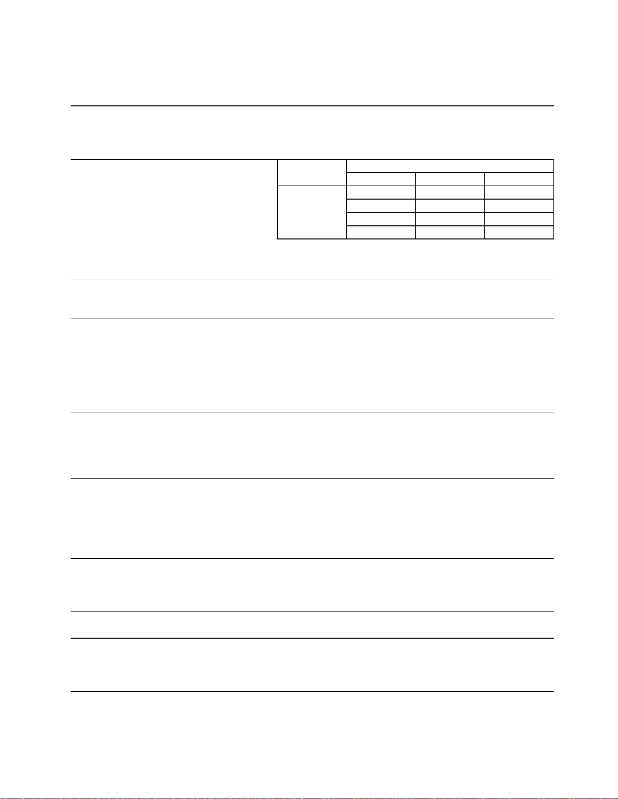
1. KM-900MAH
AC SUPPLY VOLTAGE 208/230/60/1 (3 wir e with neutral for 115V )
AMPERAGE 11 A ( 5 Min. Freeze A T 104°F / WT 80°F)
MINIMUM C IRCUIT AMPACITY 20 A
MAXIMUM FUSE SIZE 20 A
APPROXIMATE ICE PRODUCTION Ambient W ATER TEMP. (°F)
PER 24 HR. Temp.(°F)507090
lbs./ day ( kg/day ) 70 *838 (380) 804 (365) 759 (344)
Reference without *marks 80 812 (368) 759 (344) 715 (324)
90 804 (365) *721 (327) 676 (306)
100 795 (361) 710 (322) 634 (288)
SHAPE OF I CE Cresc ent Cube
ICE P RODUCTION PER CYCLE 14.3 lbs. ( 6. 5 kg ) 720 pcs.
APPROXI MATE STORAGE CAPACI TY N/A
ELECTRIC & WATER CONSUMPTION 90/70° F 70/50° F
ELECTRIC W (kWH/100 lbs.) 1965 (6.6) 1783 (5.1)
WATER gal./ 24HR (gal./ 100 lbs.) 244 (31.5) 472 (56.3)
EXTERIOR DIMENSIONS (WxDxH) 30" x 27-3/8" x 37-7/16" (762 x 695 x 950 mm)
EXTERIOR FINISH Stainless Steel, Galvanized Steel (Rear)
WEIGHT Net 216 lbs. ( 98 kg ) , Shi pping 282 lbs. (128 kg)
CONNECTIONS - ELECTRIC Permanent - Connection
- WATER SUPPLY Inlet 1/2" FPT
- DRAIN Outlet 3/4" FPT
3/8" OD Pipe
CUBE CONTROL SYSTEM Float Switch
HARVESTING CONTROL SYSTEM Hot Gas and Water, Thermistor and Timer
ICE MAKI NG WATER CONTROL Timer Controlled. Overflow Pipe
COOLING WA TER CONTROL N/A
BIN CONTROL SYSTEM Proximity Switch with Delay
COMPRESSOR Hermetic, Model CS14K6E-PFV
CONDENSER Air- cooled, Fin and tube type
EVAPORATOR Verti cal type, Stainless Steel and Copper
REFRIGERANT CONTROL Thermostatic Expansion Valve
REFRIGERANT CHARGE R-404A, 3 lb. 7 oz. ( 1550 g )
DESI GN PRESSURE High 467 PSIG, Low 230 PSIG
P.C. BOARD CIRCUIT PROTECTION High Voltage Cut-out ( Internal )
COMPRESSOR PROTECTION Auto-r eset Overload Protector ( Inter nal )
REFRI GERANT CIRCUIT PROTECTION Auto-reset High Pressure Control Switch
LOW WATER PROTECTION Float Switch
ACCESSORI ES -SUPPLIED N/A
-REQUIRED Ice Stor age Bin
OPERATING C ONDITIONS VOLTAGE RANGE 187 - 253 V
AMBIENT TEMP. 45 -100° F
W ATER SUPPLY TEMP. 45 - 90° F
WATER SUPPLY PRESSURE 10 - 113 PSIG
We reserve the right to make changes in specifications and design without prior notice.
5
Page 6
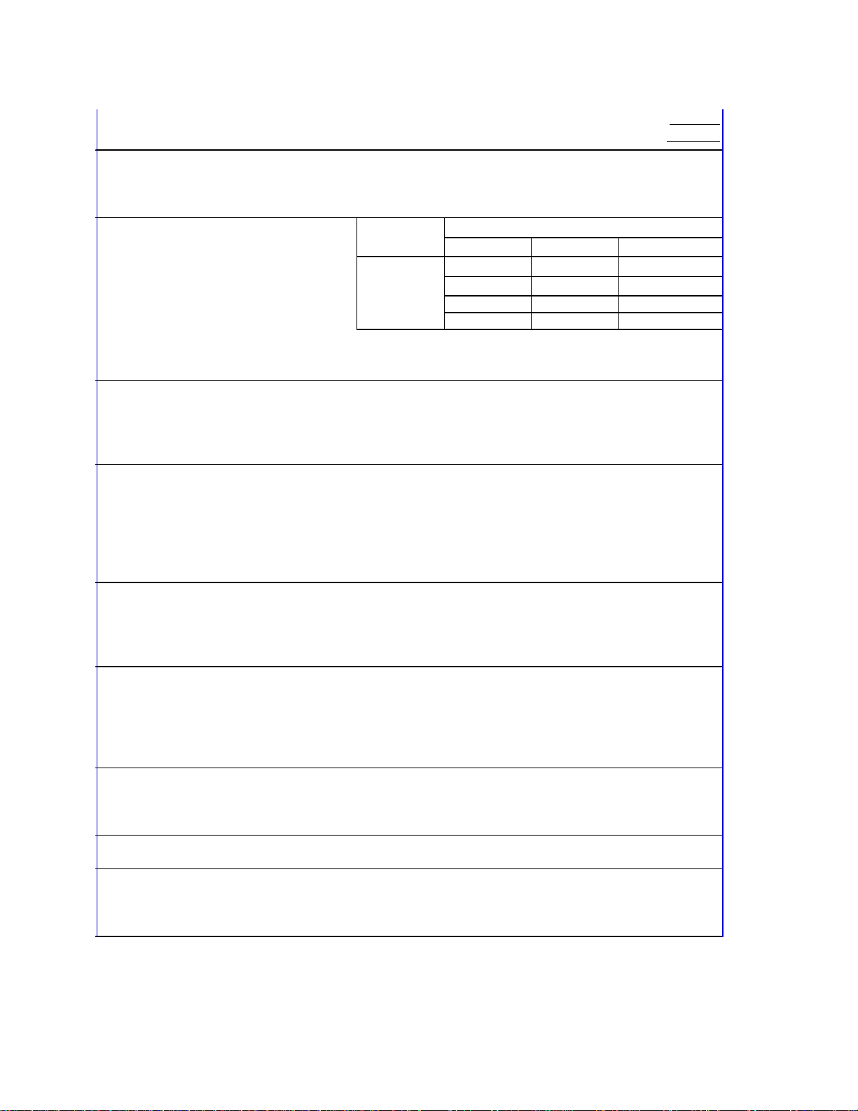
2a. KM-900MWH
g
AC SUPPLY VOLTA GE 208-230/ 60/1 (3 wire with neutral for 115 V)
AMPERAGE 10.2 A
MINIMUM CIRCUIT AMPACITY 15 A
MAXIMUM F USE SIZE 15 A
APPROXIMATE ICE PRODUCTION Ambient W ATER TEMP. (°F)
PER 24 HR. Temp.(°F) 50 70 90
lbs./day ( kg/day ) 70 *853 (387) 836 (379) 787 (357)
Reference without *marks 80 840 (381) 813 (369) 750 (340)
90 836 (379) 794 (360) 736 (334)
100 818 (371) 780 ( 354) 683 (310)
SHAPE OF ICE Crescent Cube
ICE PRODUCTION PER CYCLE 14.3 lbs. ( 6.5 kg ) 720 pc s.
APPROXIMATE STORAGE C APACITY N/A
ELECTRIC & WATER CONSUMPTION 90/70°F 70/50°F
ELECTRIC W ( kWH/100 lbs. ) 1775 (5. 3) 1768 (5. 0)
W ATER gal./24HR (gal./100 lbs.) 256 (32.2) 409 (47.9)
W ATER COOLED CONDENSER 1024 (129) 580 (68)
gal./24HR (gal./100 lbs. )
EXTERIOR DIMENSIONS (WxDxH) 30" x 27-3/8" x 37 7/16" (762 x 695 x 950 mm)
EXTERIOR FINISH Stainless Steel, Galvani zed S teel (Rear)
W E IGHT Net 211 lbs. ( 96 kg ), S hipping 277 lbs. ( 126 kg )
CONNECTIONS - ELECTRIC Per manent - Connection
- WA TER SUPPLY Inlet 1/2" FP T Condenser Inlet 1/2" FPT
- DRAI N Outlet 3/4" FPT Condenser Outlet 3/8" FPT
3/8" OD Pipe
CUBE CONTROL SYSTEM Float Swi tc h
HARVESTING CONTROL SYSTEM Hot Gas and Water, Thermistor and Timer
ICE MAKI NG WATER CONTROL Timer Controlled. Overflow Pipe
COOLING WATER CONTROL Pressure Regulator
BIN CONTROL SYSTEM Proximity Switch with Delay
COMPRESSOR Hermetic, Model CS14K6E-PFV
CONDENSER W ater- cooled, Tube in tube type
EVAPORATOR Verti cal type, Stainless Steel and Copper
REFRIGERANT CONTROL Thermostatic Expansion Valve
REFRIGERANT CHARGE R- 404A, 1 lb 7 oz. ( 650 g )
DESIGN PRESSURE High 427 PSIG, Low 230 PSIG
P.C. BOARD CIRCUIT PROTECTION High Voltage Cut-out ( Internal )
COMPRESSOR PROTECTION Auto-reset Overload Protector ( Internal )
REFRIGERANT CIRCUIT PROTECTION Auto-r eset High Pressure Control Switch
LOW WATER PROTECTION Float Swi tch
ACCESSORIES - SUPPLIED N/ A
-REQUIRED Ice Storage B i n
OPERATING CONDITIONS VOLTAGE RANGE 187 - 253 V
AMBIENT TEMP. 45 -100° F
W ATER SUPPLY TEMP. 45 - 90° F
W A TER SUPPLY PRESSURE 10 - 113 PSI G
Beginning Seri al No. L00001D
Endin
Seri al No. M20500D
We reserve the right to make changes in specifications and design without prior notice.
6
Page 7
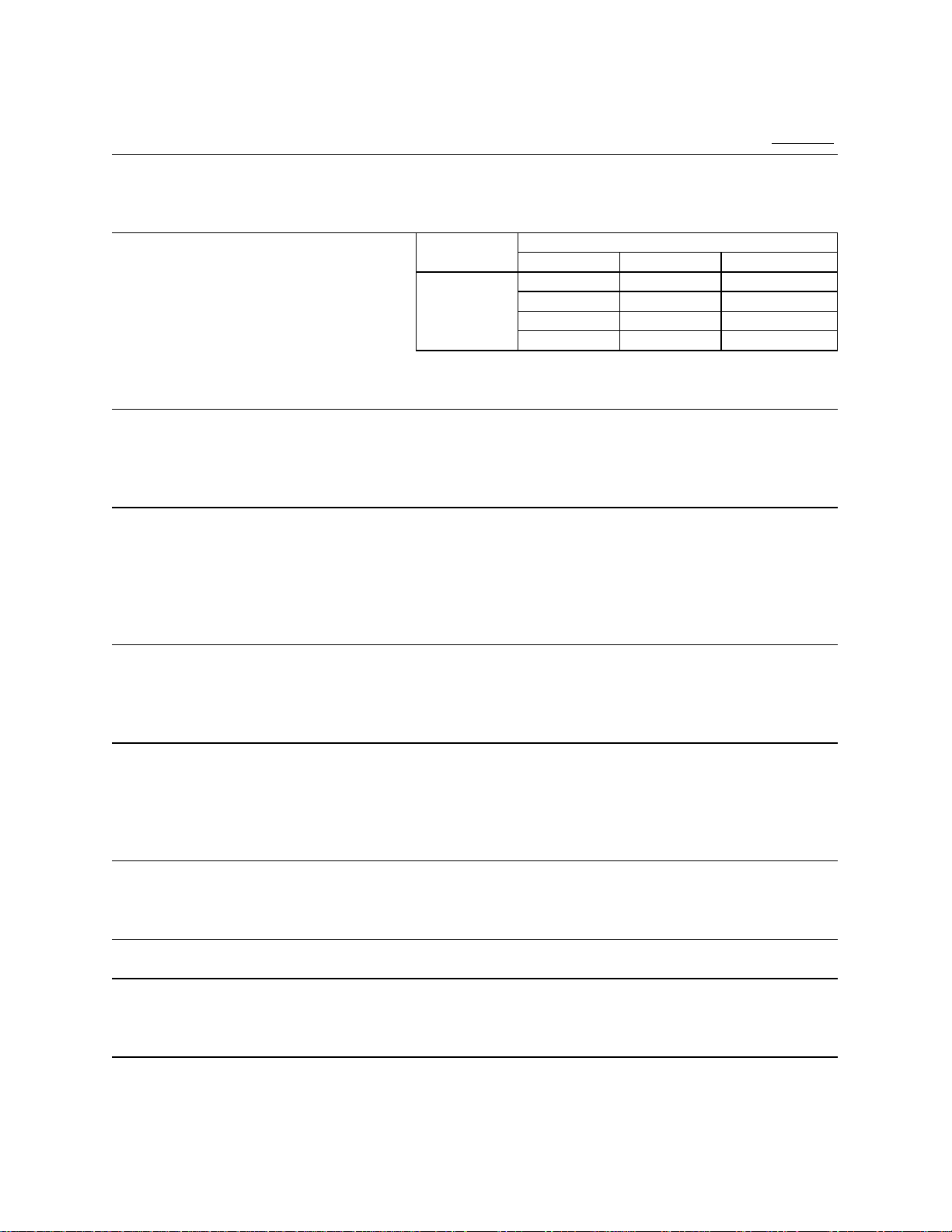
2b. KM-900MWH
Beginning Serial No. M30501D
AC SUPPLY VOLTA GE 208-230/60/1 (3 wir e with neutr al f or 115V)
AMPERAGE 10.2 A ( 5 Min. Freeze AT 104°F / WT 80°F)
MINIMUM C IRCUIT A MPA CITY 15 A
MAXIMUM FUSE SIZE 15 A
APPROXIMATE ICE PRODUCTION Ambient W ATER TEMP. ( °F)
PER 24 HR. Temp.( °F) 50 70 90
lbs./day ( kg/day ) 70 *846 (384) 830 (376) 787 (357)
Reference without *marks 80 833 ( 378 ) 808 (367) 754 (342)
90 830 (376) *790 (358) 740 (336)
100 814 (369) 778 ( 3 53) 694 (315)
SHAPE OF ICE Crescent Cube
ICE P RODUCTION PER CYCLE 14.3 lbs. ( 6.5 kg ) 720 pc s.
APPROXIMATE STORAGE CAPACITY N/A
ELECTRIC & WA TER CONSUMPTION 90/70°F 70/50° F
ELECTRIC W (kWH/100 lbs.) 1700 (5.2) 1692 (4. 8)
W A TER gal./24HR (gal./100 lbs. ) 269 (34.0) 418 ( 49.4)
W A TER COOLED COND ENSER 916 (116) 491 (58)
gal./24HR (gal./100 lbs.)
EXTERIOR DIMENSIONS (WxDxH) 30" x 27-3/8" x 37 7/16" (762 x 695 x 950 mm)
EXTERIOR FINISH Stainless Steel, Galvanized Steel (Rear)
W E IGHT Net 211 lbs. ( 96 k g ), S hipping 277 lbs. ( 126 kg )
CONNECTIONS - ELECTRIC Permanent - Connection
- WATER SUPP LY Inlet 1/2" F PT Condenser Inlet 1/2" F PT
- DRAIN Outlet 3/4" F PT Condenser Outlet 3/8" FPT
3/8" OD Pi pe
CUBE CONTROL SYSTEM Float Switch
HARVESTING CONTROL SYSTEM Hot Gas and Water , Thermistor and Timer
ICE MAKI NG WATER CONTROL Timer Controlled. Overflow Pipe
COOLING WATER CONTROL Pressure Regulator
BIN CONTROL SYSTEM Pr oximity Switch with Delay
COMPRESSOR Hermetic, Model CS14K6E- PF V-237
CONDENSER Water -c o oled, Tube in tube ty pe
EVAPORATOR Verti cal ty pe, Stainless Steel and Copper
REFRIGERANT CONTROL Thermostatic Expansion Valve
REFRIGERANT CHARGE R-404A, 1 lb. 14 oz. ( 850 g )
DESI GN PRESSURE High 427 PSIG, Low 230 PSIG
P.C. BOARD CIRCUIT PROTECTION High Voltage Cut-out ( I nternal )
COMPRESSOR P ROTECTION Auto-r eset Overload Protec tor ( I nternal )
REFRIGERANT CIRCUIT PROTECTION Auto-r eset High Pr essure Contr ol Switc h
LOW WATER PROTE CTION Float Switch
ACCESSORIES -SUPPLIED N/A
-REQUI RED Ice Storage B in
OPERATING CONDITIONS VOLTAGE RANGE 187- 253 V
AMBIENT TEMP. 45 -100° F
W ATER SUPPLY TEMP. 45 - 90° F
W ATER SUPPLY PRESSURE 10 - 113 PSIG
We reserve the right to make changes in specifications and design without prior notice.
7
Page 8
3. KM-900MRH
AC SUPPLY VOLTAGE 208-230/60/ 1 (3 wire with neutral for 115V )
AMPERAGE 12. 5 A ( 5 Min. Fr eeze AT 104°F / WT 80°F)
MINIMUM CIRCUIT AMPA CITY 20 A
MAXIMUM FUSE SIZE 20 A
APPROXI MATE ICE PRODUC TION Ambient WATER TEMP. ( °F)
PER 2 4 HR. Temp .(° F) 50 7 0 9 0
lbs./day ( kg/day ) 70 *835 ( 379) 817 (370) 786 (356)
Reference without * mar ks 80 821 (372) 792 (359) 758 (344)
90 817 (370) *772 (350) 739 (335)
100 808 ( 367) 764 (347) 708 (321)
SHAPE OF ICE Crescent Cube
ICE P RODUCTION PER CYCLE 14.3 lbs. (6. 5 kg ) 720 pcs.
APPROXIMATE STORAGE CAPACITY N/A
ELECTRIC & WATER CONSUMPTION 90/ 70° F 70/50° F
ELECTRIC W (kWH/100 lbs. ) 2060 (6. 4) 2005 ( 6. 0 )
WATER gal./24HR (gal./100 lbs.) 255 (33.0) 450 (53.9)
EXTERIOR DIMENSIONS (WxDxH) 30" x 27-3/8" x 37-7/16" ( 762 x 695 x 950 mm)
EXTERIOR FINISH Stai nless Steel, Galvanized Steel (Rear)
W E I GHT Net 216 lb s. ( 98 kg ), S hi pping 282 lbs. ( 128 kg )
CONNECTIONS - ELECTRIC Permanent - C onnection
- WATER SUPPLY Inlet 1/2" FPT
- DRAIN Outlet 3/4" FPT
3/8" OD Pipe
CUBE CONTROL SYSTEM Float Switch
HARVESTING CONTROL SYSTEM Hot Gas and Water, Thermistor and Timer
ICE MAKING WATER CONTROL Timer Contr olled. Overflow Pipe
COOLING WATER CO NTROL N/A
BIN CONTROL SYSTEM Proximity Switch with Delay
COMPRESSOR Hermetic, Model CS14K6E- PFV
CONDENSER Air- cooled Remote, Condenser Unit URC 12F
EVAPORATOR Ver tical type, Stainless Steel and Copper
REFRIGERANT CONTROL Thermostatic Expansion Valve
Condensing P ressure Regulator on URC-12F
REFRIGERANT CHARGE R-404A, 9 lbs. 14 oz. ( 4500 g )
( Ic emaker 5 lbs. 8 oz. Co nd. Unit 4 lb. 6 oz. )
DESIGN PRESSURE High 467 PSI G, Low 230 PSIG
P.C. BOARD CIRCUIT PROTECTION High Voltage Cut- out ( Internal )
COMPRESSOR PROTECTION Auto-r eset Overload Protec tor ( Inter nal )
REFRIGERANT CIRCUIT PROTECTION Auto-reset Hi gh Pr essure Control Switch
LOW WATER PROTECTION Float Switch
ACCESSORIES -SUPPLIED N/A
-REQUIRED Ice Storage Bin, Remote Condenser Unit
OPERATING CONDITIONS VOLTAGE RANGE 187 - 253 V
AMBIENT TEMP. 45 -100° F
W ATER SUPPLY TEMP. 45 - 90° F
WATER SUPPLY PRESSURE 10 - 113 PSIG
We reserve the right to make changes in specifications and design without prior notice.
8
Page 9
4. KM-900MRH3
AC SUPPLY VOLTAGE 208-230/60/3
AMPERAGE 6.5 A ( 5 Min. Freeze AT 104°F / WT 80°F)
MINIMUM C IRCUIT AMPACITY 20 A
MAXIMUM FUSE SIZE 20 A
APPROXIMATE ICE PRODUCTION Ambient W ATER TEMP. (°F)
PER 24 HR. Temp.(°F)507090
lbs./ day ( kg/day ) 70 *842 (382) 826 (375) 784 (356)
Reference without *marks 80 830 (377) 806 (366) 753 (341)
90 826 (375) *789 (358) 739 (335)
100 811 ( 368) 777 (353) 694 (315)
SHAPE OF I CE Cresc ent Cube
ICE P RODUCTION PER CYCLE 14.3 lbs. (6. 5 kg ) 720 pcs.
APPROXI MATE STORAGE CAPACI TY N/A
ELECTRIC & WATER CONSUMPTION 90/70° F 70/50° F
ELECTRIC W (kWH/100 lbs.) 2070 (6.3) 2000 (5.7)
WATER gal./ 24HR (gal./ 100 lbs.) 264 (33.4) 454 (53.9)
EXTERIOR DIMENSIONS (WxDxH) 30" x 27-3/8" x 37-7/16" (762 x 695 x 950 mm)
EXTERIOR FINISH Stainless Steel, Galvanized Steel (Rear)
WEIGHT Net 216 lbs. ( 98 kg ) , Shi pping 282 lbs. ( 128 kg )
CONNECTIONS - ELECTRIC Permanent - Connection
- WATER SUPPLY Inlet 1/2" FPT
- DRAIN Outlet 3/4" FPT
3/8" OD Pipe
CUBE CONTROL SYSTEM Float Switch
HARVESTING CONTROL SYSTEM Hot Gas and Water, Thermistor and Timer
ICE MAKI NG WATER CONTROL Timer Controlled. Overflow Pipe
COOLING WA TER CONTROL N/A
BIN CONTROL SYSTEM Proximity Switch with Delay
COMPRESSOR Hermetic, Model CS14K6E-TF5
CONDENSER Air- cooled Remote, Condenser Unit URC 12F
EVAPORATOR Verti cal type, Stainless Steel and Copper
REFRIGERANT CONTROL Thermostatic Expansion Valve
Condensing Pressur e Regulator on URC- 12F
REFRIGERANT CHARGE R-404A, 9 lbs. 14 oz. ( 4500 g )
( Ic emaker 5 lbs. 8 oz. Cond. Unit 4 lb. 6 oz. )
DESI GN PRESSURE High 467 PSIG, Low 230 PSIG
P.C. BOARD CIRCUIT PROTECTION High Voltage Cut-out ( Internal )
COMPRESSOR PROTECTION Auto-r eset Overload Protector ( Inter nal )
REFRI GERANT CIRCUIT PROTECTION Auto-reset High Pressure Control Switch
LOW WATER PROTECTION Float Switch
ACCESSORI ES -SUPPLIED N/A
-REQUIRED Ice Stor age Bin, Remote Condenser Unit
OPERATING C ONDITIONS VOLTAGE RANGE 187 - 253 V
AMBIENT TEMP. 45 -100° F
W ATER SUPPLY TEMP. 45 - 90° F
WATER SUPPLY PRESSURE 10 - 113 PSIG
We reserve the right to make changes in specifications and design without prior notice.
9
Page 10
5. CONDENSING UNIT
URC-12F
10
Page 11

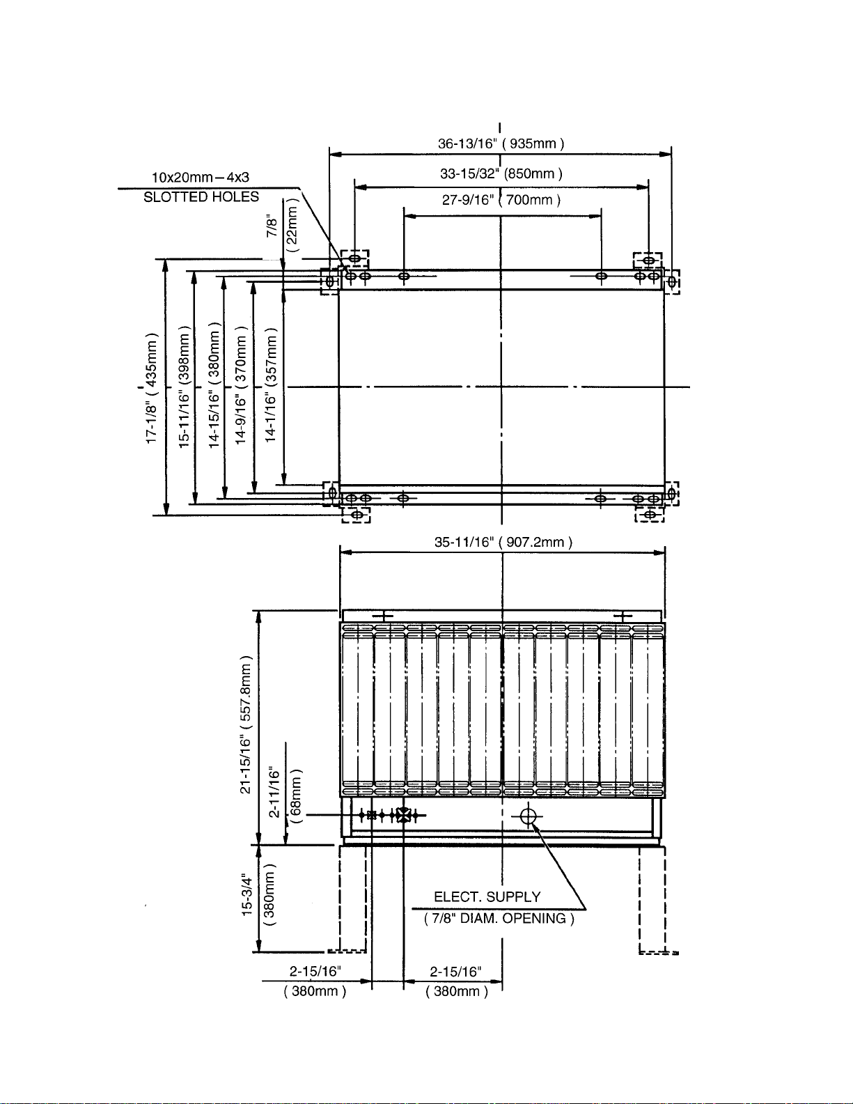
MODEL: URC-12F
SPECIFICATIONS
EXTERIOR
DIMENSIONS (W x D x H)
REFRIGERANT CHARGE
URC-12F
WEIGHT
CONNECTIONS
REFRIGERANT
ELECTRICAL
CONDENSER
HEAD PRESSURE CONTROL
AMBIENT CONDITION
Galvanized Steel
35 - 11/16” x 15-11/16” x 21-15/16”
(907.2 x 398 x 557.8 mm)
R404A 4 lbs. 7 oz. (2000 g)
Net 80 lbs. (36 kg)
Shipping 87 lbs. (39 kg)
One Shot Couplings (Aeroquip)
Permanent Connection
Air-cooled
Condensing Pressure Regulator
Min. -20°F - Max. +122°F
(-29°C to +50°C)
Outdoor use
11
Page 12
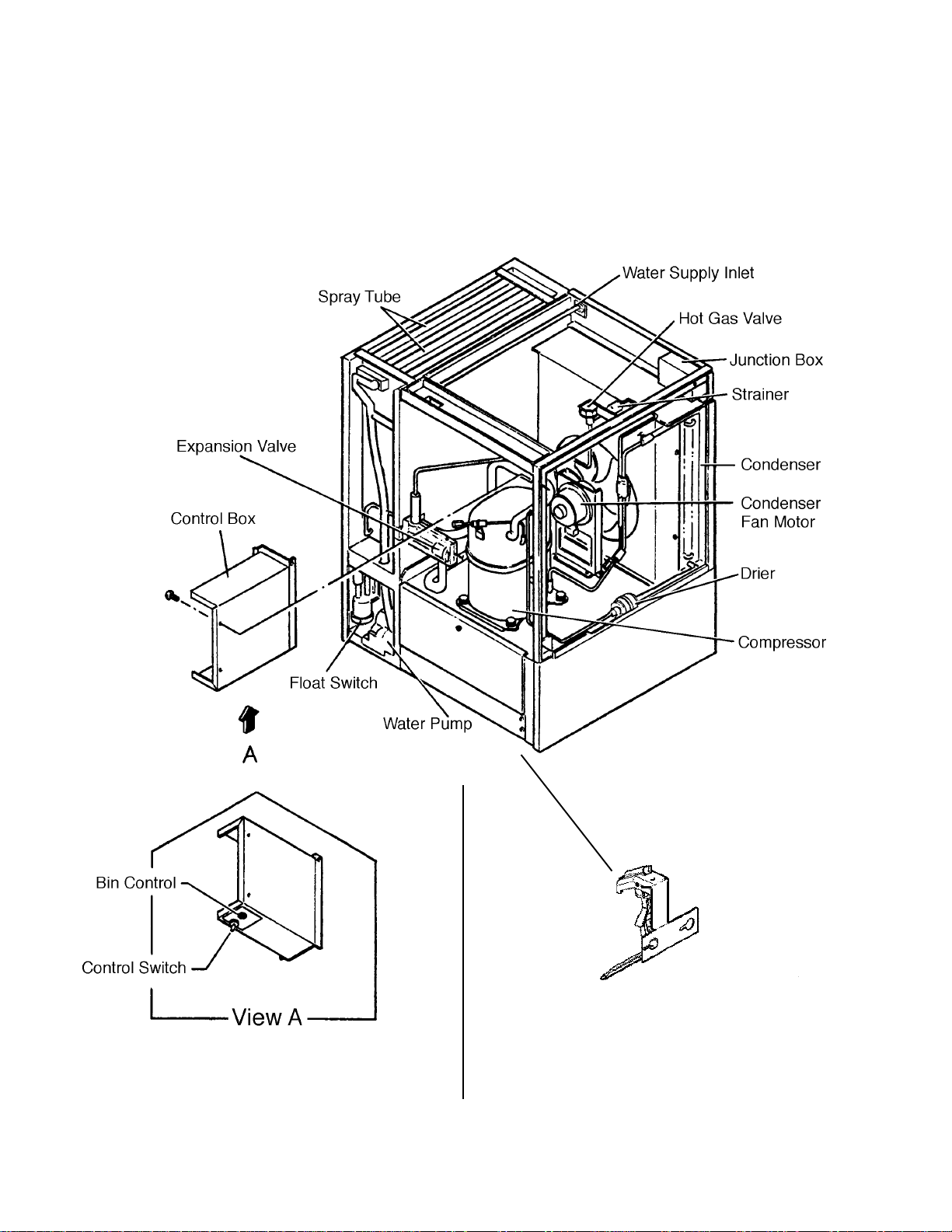
II. GENERAL INFORMA TION
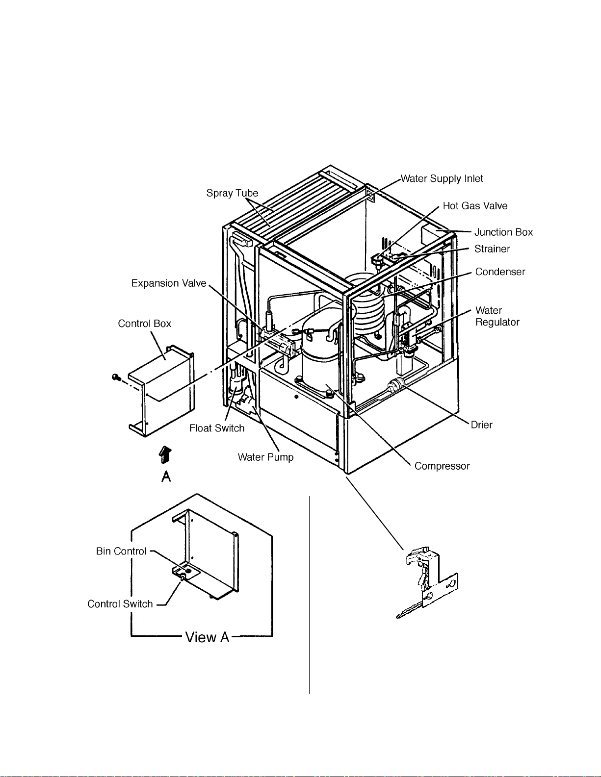
1. CONSTRUCTION
[a] KM-900MAH
Models with Thermostat
Models with Mechanical Bin Control
12
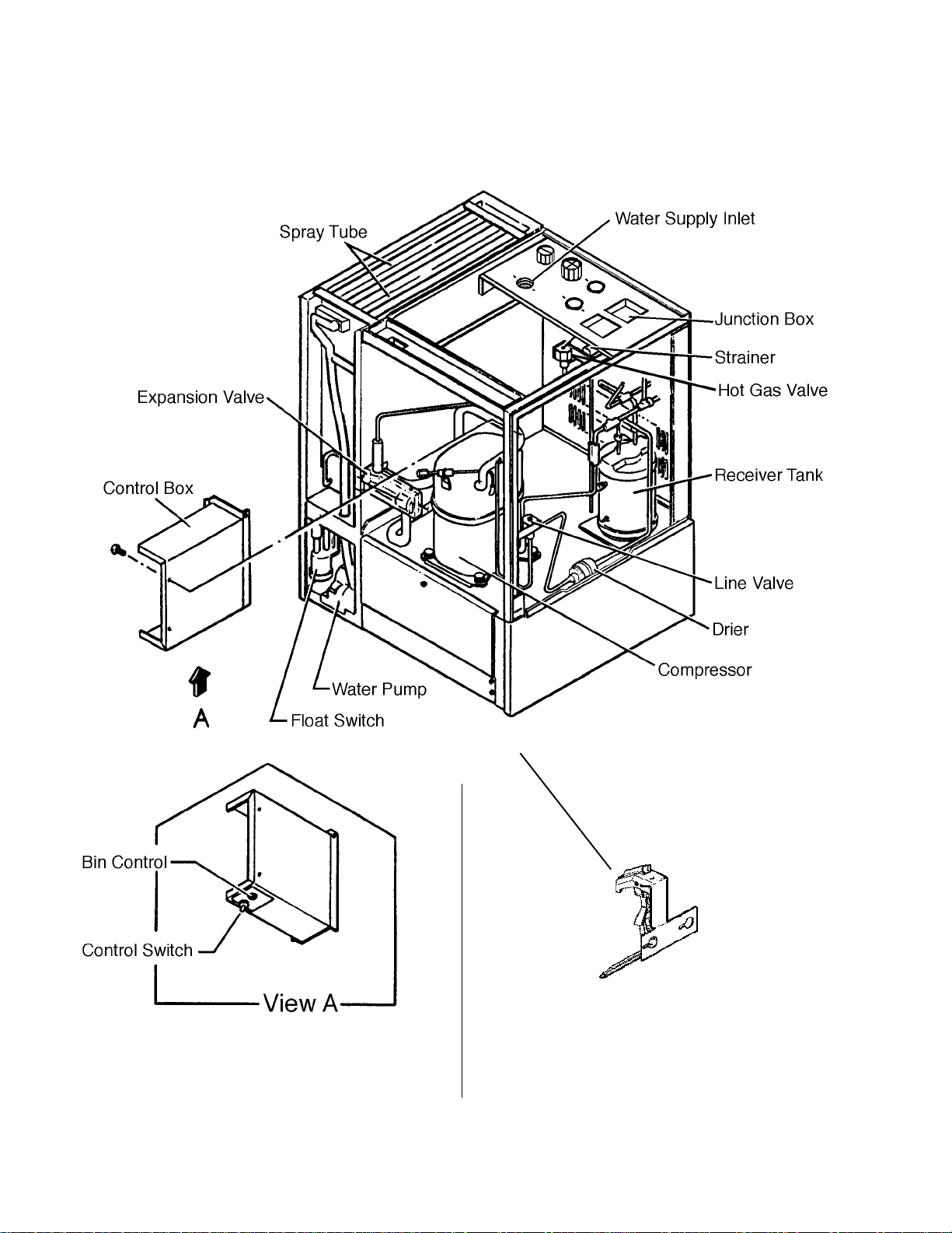
Page 13
[b] KM-900MWH
Models with Thermostat
Models with Mechanical Bin Control
13
Page 14
[c] KM-900MRH
Models with Thermostat
Models with Mechanical Bin Control
14
Page 15

[d] KM-900MRH3
Models with Thermostat
Models with Mechanical Bin Control
15
Page 16

2. CONTROLLER BOARD
[a] SOLID-STATE CONTROL
1) A HOSHIZAKI exclusive solid-state control is employed in KM-900MAH,
KM-900MWH, KM-900MRH and KM-900MRH3 Modular Crescent Cubers.
2) A Printed Circuit Board (hereafter called “Controller Board”) includes a stable and
high quality control system.
3) All models are pretested and factory-adjusted.
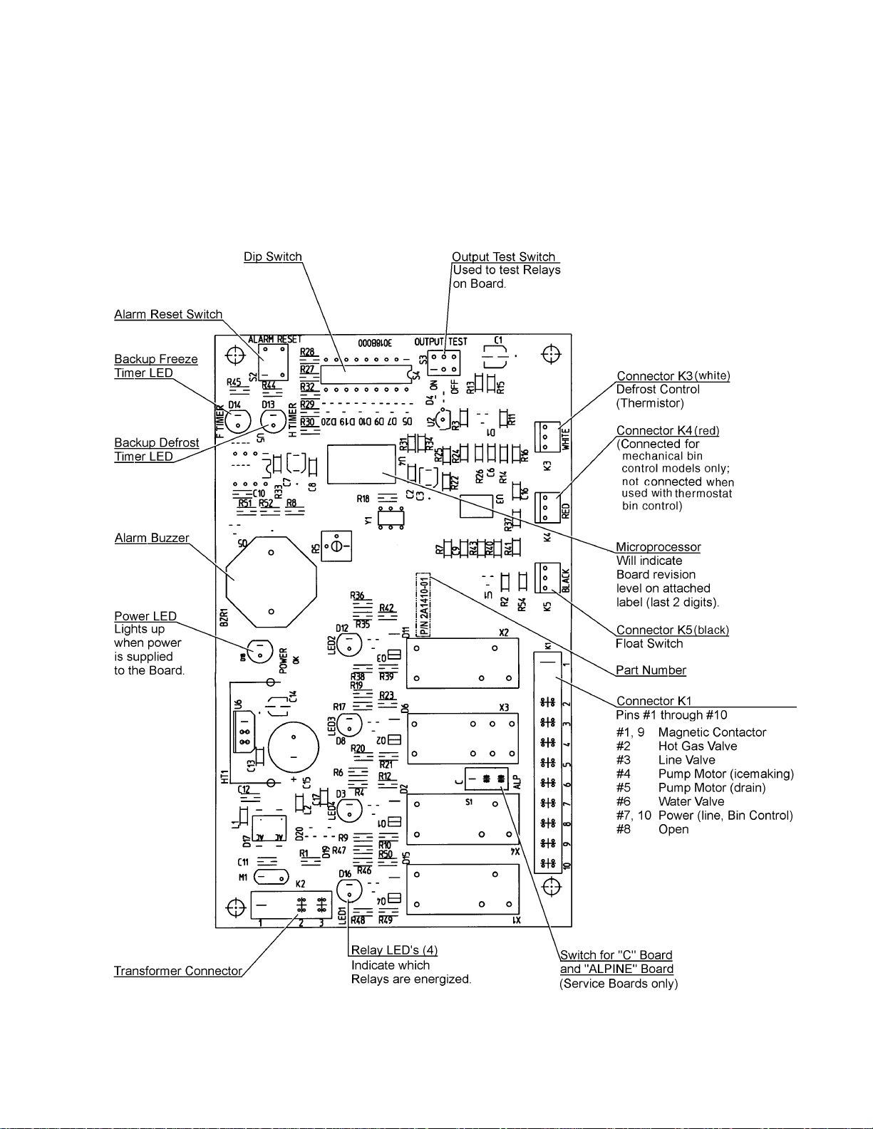
[b] CONTROLLER BOARD
CAUTION
1. Fragile, handle very carefully.
2. A controller board contains integrated circuits, which are susceptible to
failure due to static discharge. It is especially important to touch the
metal part of the unit when handling or replacing the board.
3. Do not touch the electronic devices on the board or the back of the
board to prevent damage to the board.
4. Do not change wiring and connections. Do not misconnect K3, K4 and
K5, because the same connector is used for the Thermistor (white),
Float Switch (black), and Mechanical Bin Control (red).
(For machines with thermostat, there is no connection on K4.)
5. Always replace the whole board assembly when it goes bad.
6. Do not short out power supply to test for voltage.
PART NUMBER TYPE
2A1410-01 HOS-001A (Control Products)
Features of Control Products “E” Controller Board
1) Maximum Water Supply Period - 6 minutes
Water Solenoid Valve opening, in the Defrost (Harvest) Cycle, is limited by the de-
frost timer. The Water Valve cannot remain open longer than the maximum period.
The Water Valve can close in less than six minutes if the defrost cycle is completed.
16
Page 17

2) Defrost Timer
The defrost cycle starts when the Float Switch opens and completes the freeze cycle.
But the Defrost Timer does not start counting until the Thermistor senses 48°F at the
Evaporator outlet. The period from the end of the freeze cycle up to the point of the
Thermistor's sensing varies depending on the ambient and water temperatures.
3) High Temperature Safety - 127 ± 7°F
The temperature of the suction line in the refrigerant circuit is limited by the High
Temperature Safety.
During the defrost cycle the Evaporator temperature rises. The Thermistor
senses 48°F and starts the Defrost Timer. After the Defrost Timer counts down
to zero, the normal freeze cycle begins. If the Evaporator temperature continues
to rise, the Thermistor will sense the rise in temperature and at 127 ± 7°F the
Thermistor operates the High Temperature Safety.
This High Temperature Safety shuts down the circuit and the icemaker automatically
stops.
This High Temperature Safety protects the unit from excessive temperature. The Control
Board will Beep every 3 seconds. The white Reset Button on the Control Board must be
pressed with power on to reset the Safety.
4) Low Water Safety
If the Pump Motor is operated without water, the mechanical seal can fail. To prevent
this type of failure, the Controller Board checks the position of the Float Switch at the end
of the initial one minute water fill cycle and at the end of each defrost cycle.
If the Float Switch is in the up position (electrical circuit closed), the Controller Board
changes to the ice making cycle. If the Float Switch is in the down position (electrical
circuit open), the Controller Board changes to a one minute water fill cycle before starting
the ice making cycle. This method allows for a Low Water Safety shut down to protect
the Water Pump from mechanical seal failure.
For water-cooled model, if the water is shut off, the unit is protected by the High Pressure
Switch.
5) High Voltage Cutout
The maximum allowable supply voltage of this icemaker is limited by the High Voltage Cutout.
If miswiring (especially on single phase 3 wire models) causes excessive voltage on the
Controller Board, the High Voltage Cutout shuts down the circuit in 3 seconds and the
icemaker automatically stops. When the proper supply voltage is resumed, the icemaker
automatically starts running again. The Control Board will signal this problem using 7 Beeps
every 3 seconds.
6) LED Lights and Audible Alarm Safeties
The red LED indicates proper control voltage and will remain on unless a control voltage
problem occurs. At startup a 5 second delay occurs while the board conducts an internal
timer check. A short beep occurs when the power switch is turned ON or OFF.
17
Page 18

The green LED’s 1-4 represent the corresponding relays and energize and sequence 5
seconds from initial start-up as follows:
Sequence Step LED’s on Length: Min. Max. Avg.
1 Minute Fill Cycle LED4 60 sec.
Harvest Cycle LED1, 4, & 2 2 min. 20 min. 3-5 min.
Freeze Cycle LED1 5 min. 60 min. 30-35 min.
Reverse Pump Out LED1, 3, & 2 10 sec. 20 sec. Factory set.
{LED 1 – Comp; LED 2 - HGV/CFM; LED 3 – PM; LED 4 - WV}
The built in safeties shut down the unit and have alarms as follows:
1 beep every 3 sec. = High Evaporator Temperature >127 ° F.
Check for defrost problem (stuck HGV or relay), hot water entering unit, stuck
headmaster, or shorted thermistor.
2 beeps every 3 sec. = Defrost Back Up Timer. Defrost >20 minutes.
Orange LED marked 20 MIN energizes.
Check for open thermistor, HGV not opening, TXV leaking by, low charge, or inefficient
compressor.
3 beeps every 3 sec. = Freeze Back Up Timer. Freeze > 60 minutes.
Yellow LED marked 60 MIN energizes.
Check for F/S stuck closed (up), WV leaking by, HGV leaking by, TXV not feeding
properly, low charge, or inefficient compressor.
Machines
with
mechanical
bin control
ONLY
4 beeps every 3 sec. = Short Circuit between the K4 connection on
the control board and the bin control relay. Check connections and
replace wire harness if necessary.
5 beeps every 3 sec. = Open Circuit between the K4 connection
on the control board and the bin control relay. Check connections and
replace wire harness if necessary.
To manually reset the above safeties, depress white alarm reset button with the power
supply ON.
6 beeps every 3 sec. = Low Voltage. Voltage is 92 Vac or less.
7 beeps every 3 sec. = High Voltage. Control voltage > 147 Vac ±5%.
The red LED will de-energize if voltage protection operates.
The voltage safety automatically resets when voltage is corrected.
The Output Test switch “S3” provides a relay sequence test. With power OFF, place S3
ON and switch power to ICE. The correct lighting sequence should be none, 2, 3, 4, 1, &
4, normal sequence every 5 seconds. S3 should remain in the “OFF” position for normal
operation.
18
Page 19
The application switch located between relay X3 & X4 must be set to match the original
board application. Place this switch in the ALP position if there is no white wire supplied
to the K1 connector. If there is a white wire, place the switch in the C position. If this
switch is placed in the wrong position, either the compressor contactor will remain energized with the control switch OFF, or the unit will not start.
The dip switches should be adjusted per the adjustment chart published in the Tech
Specs book. Number 8 must remain in the OFF position.
(Control Products HOS-001A Board)
19
Page 20
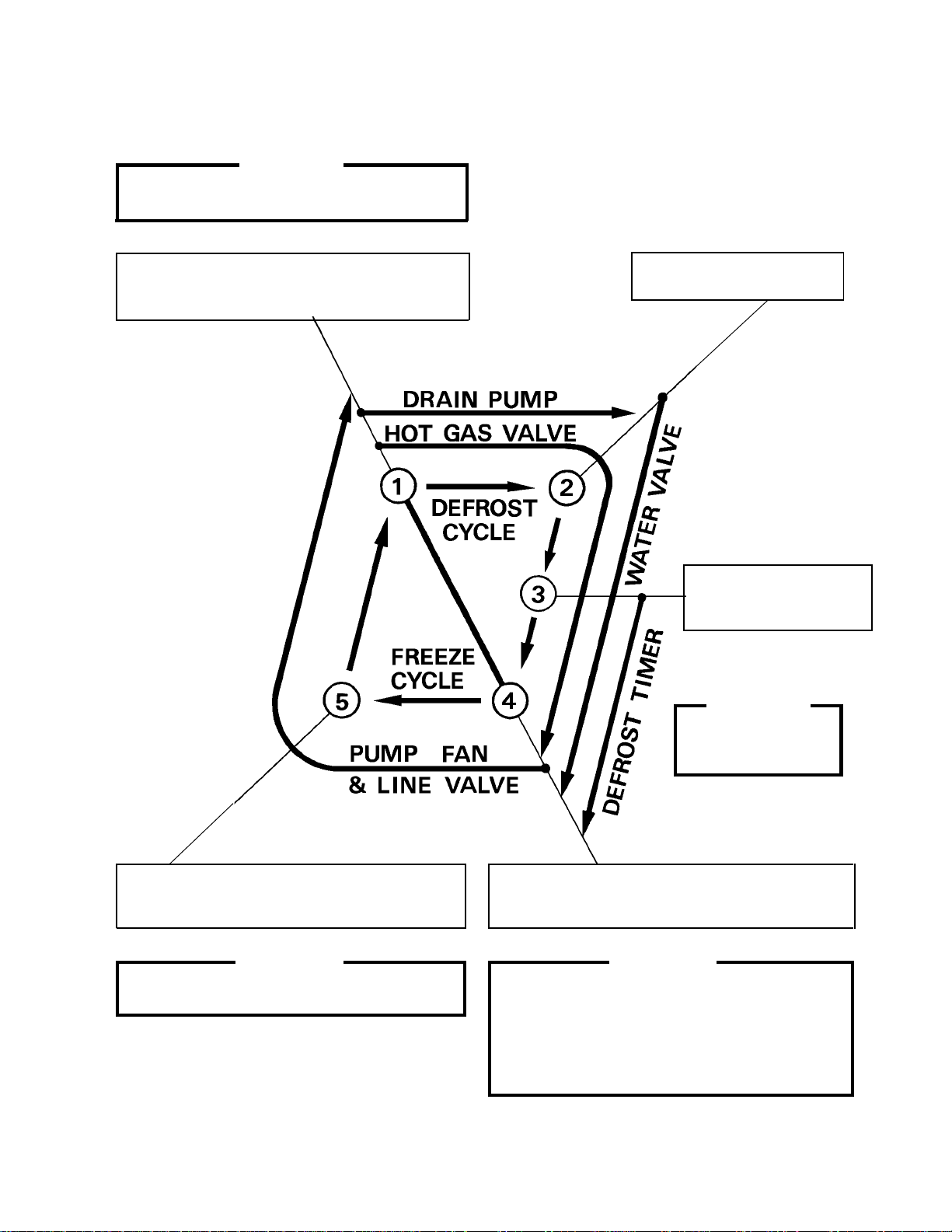
[c] SEQUENCE
1st Cycle
1. Unit energized and Control Switch to “ICE”
position. Water supply cycle starts.
2. After 1 minute,
Defrost cycle starts.
3. Thermistor reads 48° F.
Defrost Timer starts counting.
5. After the first 5 minutes in freeze cycle.
Ready to complete freeze cycle when Float
Switch circuit opens.
IMPORTANT
Board never accepts freeze completion signal
within the first 5 minutes in freeze cycle.
IMPORTANT
Water Valve
opening is limited
to 6 minutes.
&
4. Defrost Timer stops counting.
Defrost cycle is completed and freeze cycle
starts.
IMPORTANT
1. Board never accepts defrost completion
signal within the first 2 minutes in defrost
cycle.
2. Defrost cycle time is limited to 20 minutes
even if Defrost Timer does not stop counting.
20
Page 21
2nd Cycle and after with pump drain
IMPORTANT
Freeze cycle time is limited to 60 minutes even
if Float Switch does not open.
1. Float Switch opens and signals to complete
freeze cycle.
Drain timer starts counting.
&
2. Drain timer stops counting.
Pump drain is completed
3. Thermistor reads 48° F.
Defrost Timer starts
counting.
IMPORTANT
Water Valve
opening is limited to 6
minutes.
5. After the first 5 minutes in freeze cycle.
Ready to complete freeze cycle when Float
Switch circuit opens.
IMPORTANT
Board never accepts freeze completion signal
within the first 5 minutes in freeze cycle.
4. Defrost Timer stops counting.
Defrost cycle is completed and freeze cycle
starts.
IMPORTANT
1. Board never accepts defrost completion
signal within the first 2 minutes in defrost
cycle.
2. Defrost cycle time is limited to 20 minutes
even if Defrost Timer does not stop counting.
21
Page 22
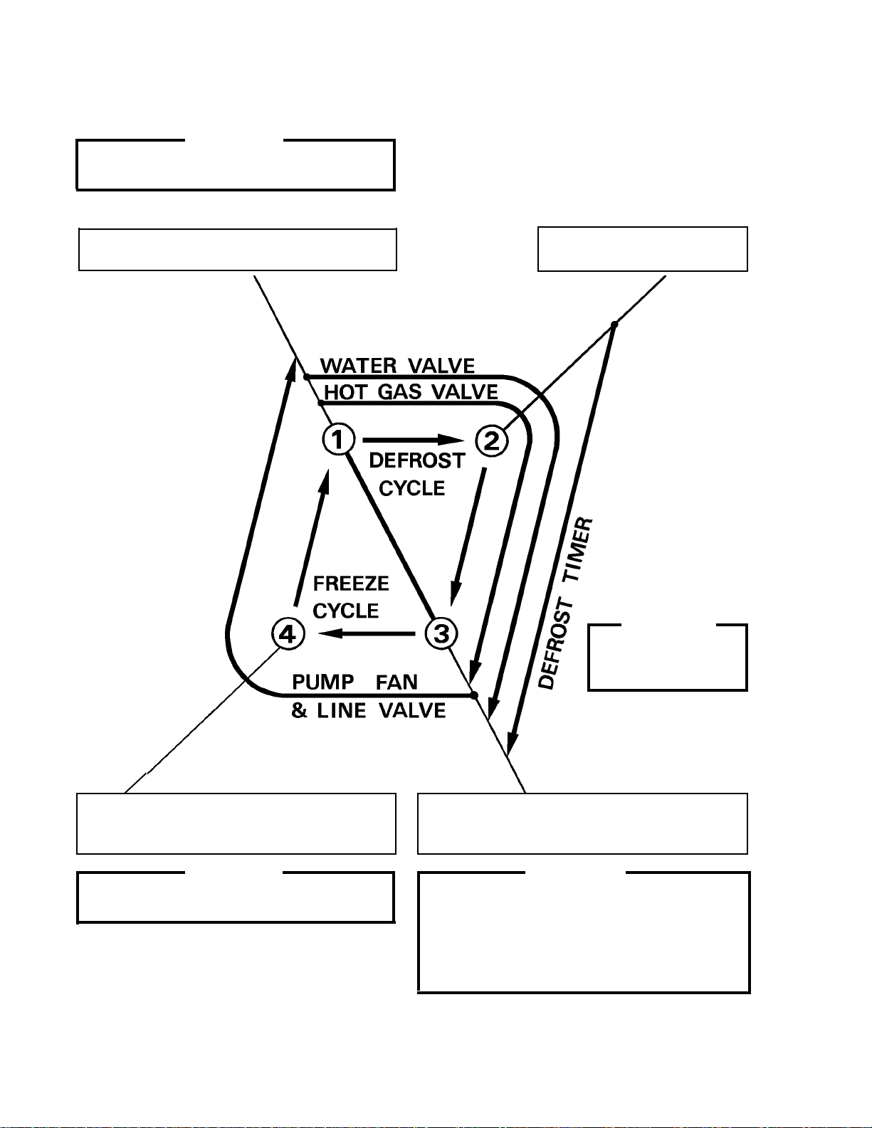
2nd Cycle and after with no pump drain
IMPORTANT
Freeze cycle time is limited to 60 minutes even
if Float Switch does not open.
1. Float Switch opens and signals to complete
freeze cycle.
&
2. Thermistor reads 48° F.
Defrost Timer starts counting.
IMPORTANT
Water Valve
opening is limited to 6
minutes.
4. After the first 5 minutes in freeze cycle.
Ready to complete freeze cycle when Float
Switch circuit opens.
IMPORTANT
Board never accepts freeze completion signal
within the first 5 minutes in freeze cycle.
3. Defrost Timer stops counting.
Defrost cycle is completed and freeze cycle
starts.
IMPORTANT
1. Board never accepts defrost completion
signal within the first 2 minutes in defrost
cycle.
2. Defrost cycle time is limited to 20 minutes
even if Defrost Timer does not stop counting.
22
Page 23

[d] CONTROLS AND ADJUSTMENTS
The Dip Switch is factory-adjusted to the following positions:
FOR MODELS WITH MECHANICAL BIN CONTROL:
DIP SWITCH NO. 1 2 3 4 5 6 7 8 9 10
KM-900MRH/3 OFF OFF ON OFF ON ON ON OFF OFF ON
KM-900MAH, OFF OFF ON OFF ON ON ON OFF OFF ON
KM-900MWH
FOR MODELS WITH THERMOSTAT :
DIP SWITCH NO. 1 2 3 4 5 6 7 8 9 10
KM-900MRH/3 OFF OFF ON OFF ON ON OFF OFF OFF ON
KM-900MAH, OFF OFF ON OFF ON ON OFF OFF OFF ON
KM-900MWH
Switch Nos. 1 and 2:
Used for adjustment of the Defrost Timer.
The Defrost Timer starts counting when the Thermistor reads a certain temperature
at the Evaporator outlet.
Switch Nos. 3 and 4:
Used for adjustment of the Drain Timer.
When a freeze cycle is completed, the Pump Motor stops, and the icemaker
resumes operation in 2 seconds. Then the Pump Motor drains the Water Tank
for the time determined by the Drain Timer. The Drain Timer also determines
the
time to restrain completion of a defrost cycle, i.e. the minimum defrost time.
Switch Nos. 5 and 6:
Used for adjustment of the Drain Counter.
The Pump Motor drains the Water Tank at the frequency determined by the Drain
Counter.
Switch No. 7:
Used only on models with mechanical bin control. Dip Switch should be set
“ON”.
(Models with bin thermostat, Switch No. 7 should be set in the “OFF” position.)
Switch No. 8:
Used only for checking the Controller Board. Usually set in OFF position.
23
Page 24

Switch Nos. 9 and 10:
Used for adjustment of Freeze Timer.
The Freeze Timer determines maximum
freeze cycle time. Upon termination of
Freeze Timer, machine initiates the
harvest cycle. After 2 consecutive timer
terminations, machine will shut down,
possibly indicating a problem.
1) Defrost Control
A thermistor (Semiconductor) is used for a defrost control sensor. The resistance
varies depending on the Suction Line temperatures. The Thermistor detects the
temperature of the Evaporator outlet to start the Defrost Timer. No adjustment is
required. If necessary, check for resistance between Thermistor leads, and visually
check the Thermistor mounting, located on the Suction Line next to the Evaporator
outlet.
Temperature (°F) Resistance (kΩ)
0 14.401
10 10.613
32 6.000
50 3.871
70 2.474
90 1.633
Check a thermistor for resistance by using the following procedures.
(i) Disconnect the connector K3 on the board.
(ii) Remove the Thermistor. See “V. 11. REMOVAL AND REPLACEMENT OF
THERMISTOR.”
(iii) Immerse the Thermistor sensor portion in a glass containing ice and water for 2 or 3
minutes.
(iv) Check for a resistance between Thermistor leads.
Normal reading is within 3.5 to 7 kΩ. Replace the Thermistor if it exceeds the normal
reading.
24
Page 25

2) Defrost Timer
No adjustment is required under normal use, as the Defrost Timer is adjusted to the suit-
able position. However, if necessary when all the ice formed on the Evaporator does not
fall into the bin in the harvest cycle, adjust the Defrost Timer to longer setting by adjusting
the Dip Switch (No. 1 & 2) on the Controller Board.
SETTING TIME
Dip Switch Dip Switch
No. 1 No. 2
OFF OFF 60 seconds
ON OFF 90 seconds
OFF ON 120 seconds
ON ON 180 seconds
3) Drain Timer
The Drain Timer is factory-adjusted, and no adjustment is required.
SETTING TIME
Dip Switch Dip Switch
No. 3 No. 4 T1 T2
OFF OFF 10 seconds 150 seconds
ON OFF 10 seconds 180 seconds
OFF ON 10 seconds 120 seconds
ON ON 20 seconds 180 seconds
T1: Time to drain the Water Tank
T2: Time to restrain defrost completion
4) Drain Counter
CAUTION
Do not adjust the Drain Counter, or the Evaporator may freeze up.
The Drain Counter is factory-adjusted to drain the Water Tank every 10 cycles, and no
adjustment is required. However, where water quality is bad and the icemaker needs a
pump drain more often, the Drain Counter can be adjusted as shown in the table below:
25
Page 26

SETTING FREQUENCY
Dip Switch Dip Switch
No. 5 No. 6
OFF OFF every cycle
ON OFF every 2 cycles
OFF ON every 5 cycles
ON ON every 10 cycles
5) Freeze Timer
CAUTION
Adjust to proper specification, or the unit may not operate correctly.
Two new dip switches numbered 9 and 10 have been added to the improved “E”
board to better prevent possible freeze ups. These settings come factory set to the
default setting of 60 min. (OFF, OFF). Check the adjustment chart published in the
Tech Specs for proper settings. If the old board does not have these two dip
switches, (only 8 instead of 10), leave setting as OFF, OFF.
6) Bin Control
MODELS WITH THERMOSTAT
When the ambient temperature is below 45°F, the Bin Control Thermostat
operates to stop the icemaker even if the Ice Storage Bin is empty.
When the Thermostat is set in the prohibited range, the icemaker operates continuously even if the Ice Storage Bin is filled with ice. Setting in
the prohibited range might cause severe damage to the icemaker resulting in failure.
SETTING TIME
Dip Switch Dip Switch
No. 9 No. 10
OFF OFF 60 min.
ON OFF 70 min.
OFF ON 50 min.
ON ON 60 min.
CAUTION
No adjustment is required under normal use, as the Bin Control is factory-adjusted.
Adjust it, if necessary, so that the icemaker stops automatically within 10 seconds after
ice contacts the Bin Control Thermostat Bulb.
26
Page 27

MODELS WITH MECHANICAL BIN CONTROL
CAUTION
Dip Switch No. 7 must be set to the ON position. If No. 7 is set to the OFF
position, the machine will run continuously, causing a freeze-up condition.
No adjustment is required. The Bin Control is factory-adjusted.
[e] CHECKING THE CONTROLLER BOARD
1) Visually check the sequence with the icemaker operating.
2) Visually check the Controller Board by using the following procedures.
(i) Adjust the Defrost Timer to minimum position.
Disconnect the Thermistor from the Controller Board.
Connect a 1.5 kΩ - 3.5 kΩ resistor to the Connector K3 (pins #1 and #2), and energize
the unit.
After the 1 minute ± 5 second water supply cycle and the 2 minute ± 10 second defrost
cycle, the unit should start the freeze cycle.
(ii) After the above step (i), disconnect the Float Switch leads from the Controller Board
within the first 5 minutes of the freeze cycle.
The unit should go into the defrost cycle after the first 5 minutes ± 20 seconds of
the freeze cycle.
(iii) Reconnect the Float Switch Connector to the Controller Board. After the first 5
minutes of the freeze cycle, disconnect the Float Switch leads from the Controller
Board.
At this point, the unit should start the defrost cycle.
(iv) After Step (iii), de-energize the unit and confirm that the Defrost Timer is in the
minimum position. Disconnect the resistor from the Controller Board, and energize the unit.
After the 1 minute water supply cycle, the defrost cycle starts.
Reconnect a 1.5 kΩ - 3.5 kΩ resistor to the Connector K3 (pins #1 and #2) after
the first 2 minutes of the defrost cycle.
The unit should start the freeze cycle after 1 minute ± 5 seconds from the resis-
tor connection.
27
Page 28

3) Check the Controller Board by using test program of the Controller Board.
The Output Test Switch “S3” provides a relay sequence test. With power OFF, place S3 on
and switch power to ICE. The correct lighting sequence should be none, 2, 3, 4, 1, and 4,
normal sequence every 5 seconds. S3 should remain in the “OFF” position for normal
operation.
3. MECHANICAL BIN CONTROL
(THESE INSTRUCTIONS NOT APPLICABLE TO MODELS WITH THERMOSTAT)
[a] PROXIMITY SWITCH
1) This machine uses a lever-actuated proximity switch (hereafter called “mechanical bin
control”) to control the ice level in the storage bin.
[b] EXPLANATION OF OPERATION
1) The startup and shutdown of the ice machine is controlled via the controller board. Dip
Switch number 7 must be in the ON position for the controller board to receive input from
the bin control.
(i) The controller board receives a resistance value input via the red K4 connector
from the bin control. A resistor wire harness is connected from the bin control to
the controller board.
(ii) When the bin control is activated in the bin full position (pushed to the right), a
15.8 KΩ signal will be sent to the control board to shut down the unit.
(iii) When the bin control is in the normal position (bin is not full), a 7.9 KΩ reading is
sent to the control board to continue operation.
2) During operation, the controller board will only shut down the machine if a 15.8 KΩ signal is
received from the bin control during the first 5 minutes of the freeze cycle.
(i) If ice pushes the lever to the right after the first five minutes of the freeze cycle,
the controller board will allow the machine to complete the freeze cycle and the
following harvest cycle before shutting down the machine. This will prevent
incomplete batches of ice from forming on the evaporator.
28
Page 29

[c] TROUBLESHOOTING (MECHANICAL BIN CONTROL ONLY)
1) Machine will not start
(i) Move dip switch No. 7 to the “OFF” position. If the machine starts up within a few
seconds, the bin control is the likely problem. If the machine does not start up,
refer to Section “IV. Service Diagnosis” to verify that non-bin control related issues
are resolved.
(ii)
Check to make sure shipping tape has been removed and the wires are connected
properly.
(iii) Check to make sure no obstruction prevents the lever from moving to the bin empty
position.
2) Machine will not shut off
(i)
Refer to Section “IV. Service Diagnosis” to verify that non-bin control related issues
are resolved.
(ii) Dip switch No. 7 should be in the on position. If the switch is in the off position, the
controller board will not receive input from the bin control.
(iii) Move the lever to the far right.
a. If the machine does not shut off, check the resistance values of the resistor
wire harness. You should read approximately 15.8 KΩ between the black
terminal and the red terminal that connect to the K4 connector on the controller board, when the lever is in the bin full position (far right). If this reads
approximately 7.9 KΩ, the resistors may be miswired. Switch the black and
white wires in the terminal housing or order a replacement wire harness.
b. Check the stainless steel bracket that the bin control is mounted to.
c. If the preceding items do not resolve the problem, replace the Bin Control
Assembly.
29
Page 30

III. TECHNICAL INFORMA TION
1. WATER CIRCUIT AND REFRIGERANT CIRCUIT
[a] KM-900MAH
30
Page 31

[b] KM-900MWH
31
Page 32

[c] KM-900MRH and KM-900MRH3
32
Page 33

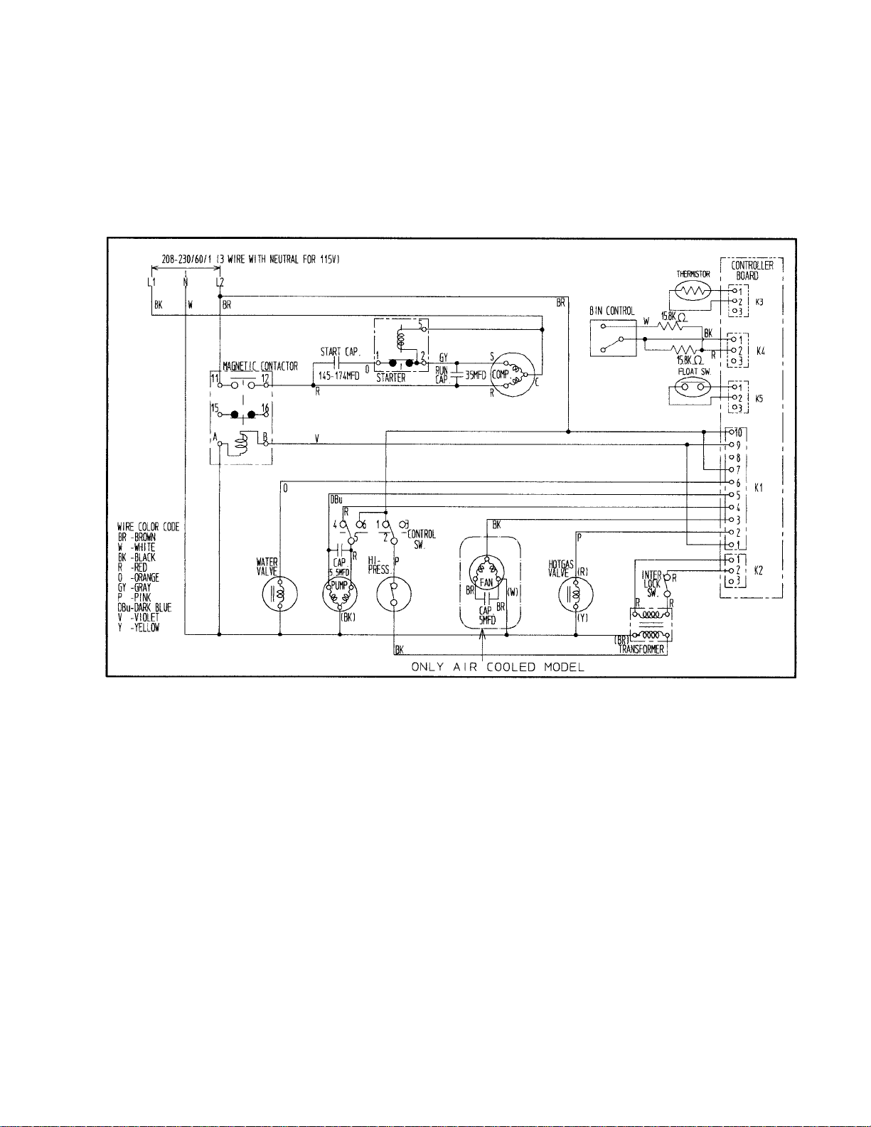
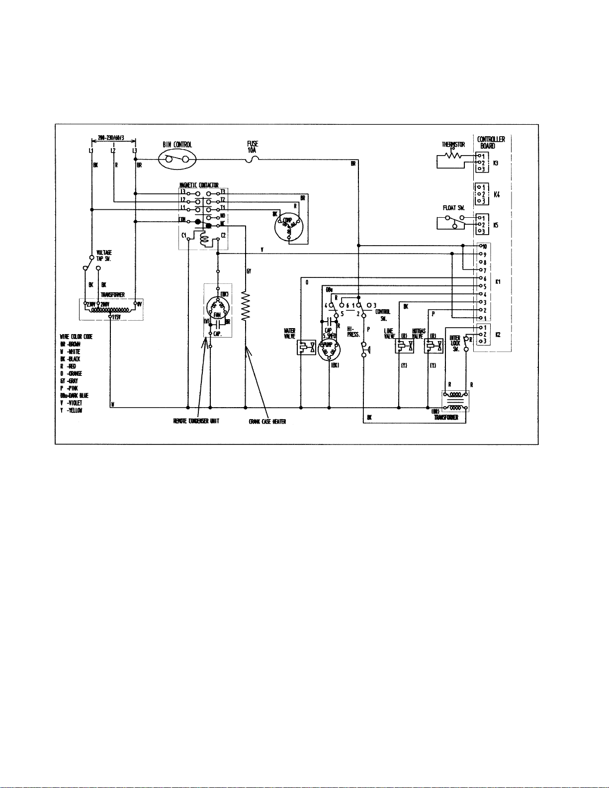
2. WIRING DIAGRAMS
[a] KM-900MAH (With Mechanical Bin Control, Aux. Codes L-0 through M-1)
Note: Pressure Switch
Cut-out 412 ± PSIG
Cut-in 327 ± 21 PSIG
21
0
33
Page 34

KM-900MAH (With Thermostat, Aux. Codes M-2 and after)
Note: Pressure Switch
Cut-out 412 ± PSIG
Cut-in 327 ± 21 PSIG
21
0
34
Page 35
[b] KM-900MWH (With Mechanical Bin Control, Aux. Codes L-0 through M-3)
Note: Pressure Switch
Cut-out 384 ± PSIG
Cut-in 284 ± 21 PSIG
21
0
35
Page 36

KM-900MWH (With Thermostat, Aux. Codes M-4 and after)
Note: Pressure Switch
Cut-out 384 ± PSIG
Cut-in 284 ± 21 PSIG
21
0
36
Page 37

[c] KM-900MRH (With Mechanical Bin Control, Aux. Codes L-0 through M-1)
Note: Pressure Switch
Cut-out 412 ± PSIG
Cut-in 327 ± 21 PSIG
21
0
37
Page 38

KM-900MRH (With Thermostat, Aux. Codes M-2 and after)
Note: Pressure Switch
Cut-out 412 ± PSIG
Cut-in 327 ± 21 PSIG
21
0
38
Page 39
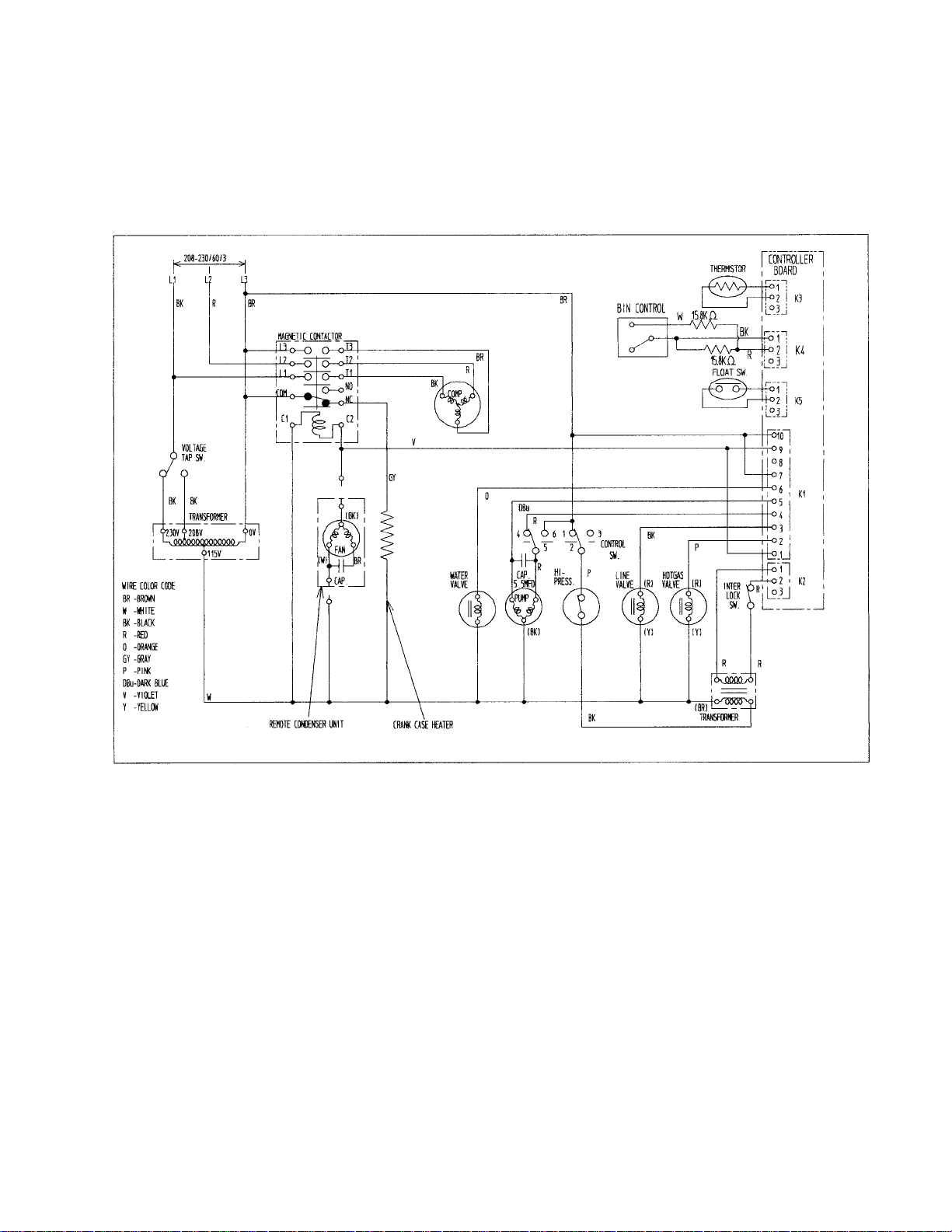
[d] KM-900MRH3 (With Mechanical Bin Control, Aux. Codes L-0 through M-0)
Note: Pressure Switch
Cut-out 412 ± PSIG
Cut-in 327 ± 21 PSIG
21
0
39
Page 40
KM-900MRH3 (With Thermostat, Aux. Codes M-1 and after)
Note: Pressure Switch
Cut-out 412 ± PSIG
Cut-in 327 ± 21 PSIG
21
0
40
Page 41

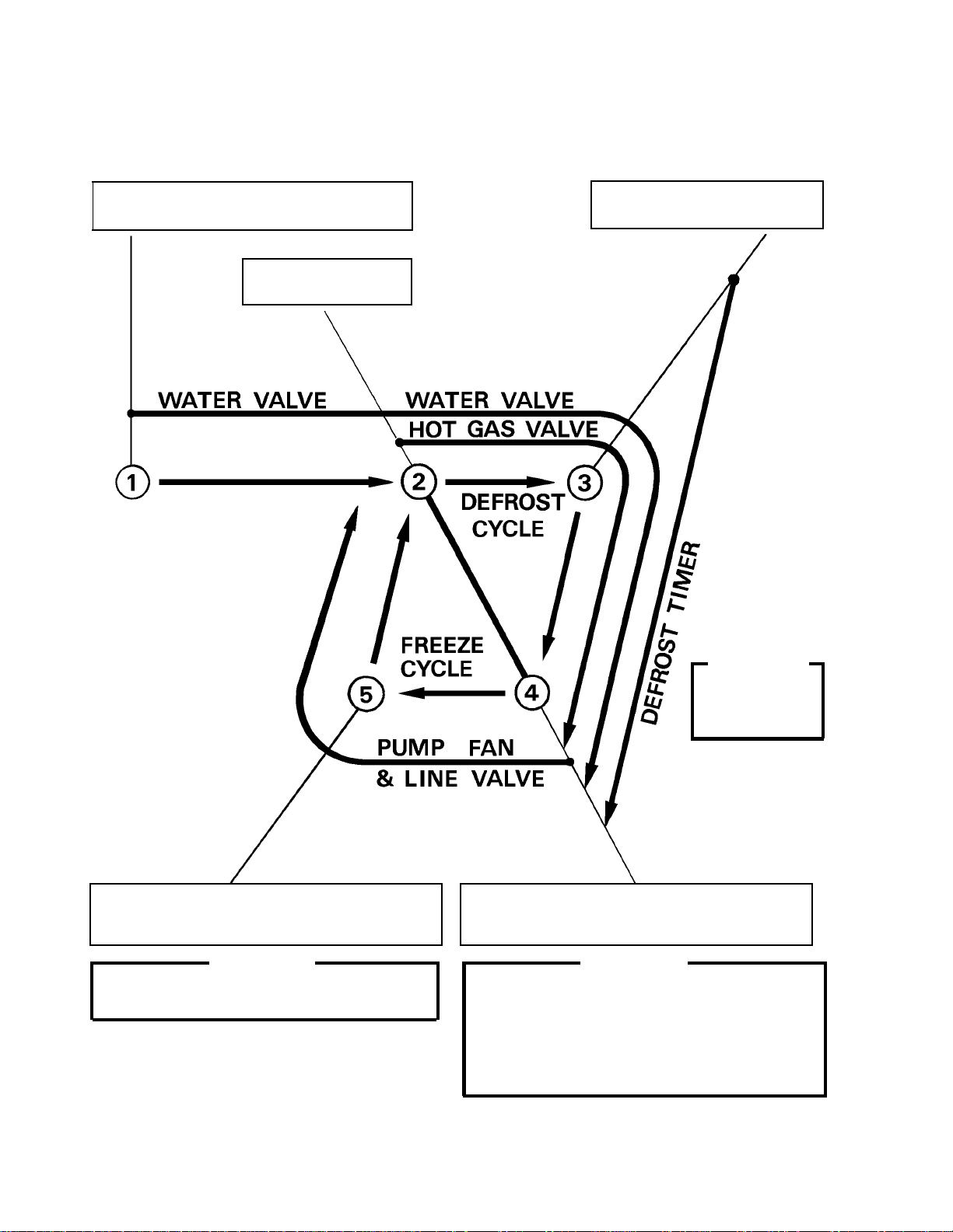
3. TIMING CHART
41
Page 42

42
Page 43

4. PERFORMANCE DATA
[a] KM-900MAH
APPROXIMATE ICE
PROD UCTION PER 24 HR.
lbs./day kg./day
APPROXIMATE ELECTRIC
CONSUMPTION
watts 100/38
APPROXIMATE WATER
CONS UMPTION PER 24 HR.
gal./day m3/day
FREEZING CYCLE TIME
min. 100/38
HARVEST CYCLE TIME
min. 100/38
HEAD PRES SURE
PSIG kg/cm2G
SUCTI ON PRESSURE
PSIG kg/cm2G 100/38 37 2.6 43 3.0
AMBIENT TEMP.
(ºF/ºC)
70/21
80/27 812 368 759 344 715 324
90/32 804 365
100/38 795 361 710 322 634 288
70/21
80/27
90/32
70/21
80/27 421 1.59 317 1.20 292 1.10
90/32 410 1.55
100/38 405 1.53 235 0.89 174 0.66
70/21
80/27
90/32
70/21
80/27
90/32
70/21
80/27 262 18.4 296 20.8 324 22.7
90/32 267 18.8
100/38 272 19.1 327 23 .0 375 26.4
70/21
80/27 35 2.5 39 2.7 43 3.0
90/32 36 2.5
50/10 70/21 90/32
838
1783
1824
1860
1900
472
21
22
22
23
4.5
4.1
4.0
3.9
245
33
WATER TEMP. (ºF/º C)
380 804 365 759 344
721
1.79
17.2
2.3 36 2.5 40 2.8
405 1.53 356 1.35
244
267 18.8 296 20.8
320
42
327
1836
1907
1965
1967
0.92
22
24
26
27
3.9
3.1
2.5
2.4
22.5
3.0
676 306
1860
1920
1973
1980
208 0.79
25
27
29
31
3.5
3.0
2.2
2.0
349 24.5
46 3.2
50
3.5
TOTAL HEA T OF REJECTION FROM CONDEN SER
14800 BTU/h [ A T 90ºF (32ºC) / WT 70ºF (21ºC)]
Note: Pressure data is recorded at 5 minutes into freeze cycle. The data not in bold should be used for
reference only.
We reserve the right to make changes in specifications and design without prior notice.
43
Page 44

[b] KM-900MWH
Beginni ng Seri al No. L00001D
Ending Serial No. M20500D
APPROXIMATE ICE
PRODUCTION PER 24 HR.
lbs./day kg./day
APPROXIMATE ELECTRIC
CONSUMPTION
wat ts 100/38
APPROXIMATE W ATER
CONS UMPTION P ER 24 HR.
gal./day m3/day
FREEZI NG CYCLE TIME
min. 100/38
HARV EST CYCLE TIME
min. 100/38
HEAD PRESSURE
PSIG kg/c m2G
SUCTION PRESSURE
PSIG kg/c m2G
AMBIENT TEMP.
(ºF/ºC)
70/21
80/27
90/32
100/38
70/21
80/27
90/32
70/21
80/27
90/32
100/38
70/21
80/27
90/32
70/21
80/27
90/32
70/21
80/27
90/32
100/38
70/21
80/27
90/32
100/38
WATER TEMP. (ºF/ºC)
50/10 70/21 90/32
853
387
836 379 787 357
840 381 813 369 750 340
836 379
794
360
736 334
818 371 780 354 683 310
989
1768
1770
1770
1773
3.74
1770
1773
1775
1777
1074 4.07 1362 5.16
1778
1783
1784
1793
1054 3.99 1186 4.49 1570 5.94
1074 4.07
1280
4.85
1629 6.17
1190 4.50 1362 5.16 1950 7.38
278
21
21
22
22
3.5
3.3
3.2
3.2
19.5
22
22
23
23
3.2
2.8
2.5
2.4
280 19.7 290 20.4
23
25
25
27
2.9
2.6
2.2
2.0
280 19.7 283 19.9 297 20.9
280 19.7
285
20.0
298 21.0
285 20.0 288 20.3 310 21.8
37
2.6
38 2.7 41 2.9
38 2.7 40 2.8 43 3.0
38 2.7
42
39 2.7 43 3.0
3.0
45 3.1
47
3.3
TOTAL HEAT OF REJECTIO N FROM CONDENSE R
TOTAL HEAT OF REJECTION FROM COMPRESSOR
W A TER FLOW FOR CONDENSER 79 gal. / h (AT 100ºF (38ºC) / WT 90ºF (32ºC))
PRESSURE DROP OF COOLING WATER LINE
Note: Pressure data is recorded at 5 minutes into freeze cycle. The data not in bold should be used for
reference only.
We reserve the right to make changes in specifications and design without prior notice.
14400 BTU/h [AT 90ºF (32ºC) / WT 70ºF (21ºC)]
2445 BTU/h [AT 90ºF (32ºC) / WT 70ºF (21ºC)]
less than 10 PSIG
44
Page 45

[c] KM-900MWH
Beginning Seri al No. M30501D
APPROXIMATE ICE
PRO DUCTION PER 24 HR.
lbs./day kg./day
APPROXIMATE ELECTRI C
CONSUMPTION
watt s 100/38
APPROXIMATE WATER
CONSUMPTION PER 24 HR.
gal./ da y m3/day
FREEZING CYCLE TIME
min. 100/38
HARVEST CYCLE TIME
min. 100/38
HEAD PRESSURE
PSIG kg/cm2G
SUCTION PRESSURE
PSIG kg/cm2G
AMBIENT TEMP.
(ºF/ºC)
70/21 *846 384 830 376 787 357
80/27 833 378 808 367 754 342
90/32 830 376 *790 358 740 336
100/38 814 369 778 353 *694 315
70/21
80/27
90/32
70/21 *909 3.44
80/27 971 3.67 1164 4.41 1284 4.86
90/32 990 3.75 *1185 4.49 1365 5.17
100/38 1185 4.49 1365 5.17 *1530 5.79
70/21
80/27
90/32
70/21
80/27
90/32
70/21 *280 19.7
80/27 280 19.7 280 19.7 292 20.5
90/32 280 19.7 *280 19.7 290 20.4
100/38 284 20.0 284 20.0 300 21.1
70/21 *36 2.5 38 2.7 39 2.7
80/27 38 2.6 41 2.9 41 2.9
90/32 38 2.7 *43 3.0 44 3.1
100/38 38 2.6 43 3.0 *44 3.1
50/10
*1692
1694
1694
1695
*21
21
22
22
*3.9
3.6
3.5
3.5
WATER TEMP. (ºF/ºC)
70/21 90/32
1694
1697
*1700
1701
990 3.75 1150 4.35
22
22
23
3.5
2.9
*2.4
2.4
280 19.7 288 20.2
*1706
1697
1701
1703
23
25
25*23
*27
3.2
2.8
2.2
*2.0
TOTAL HEAT OF REJECTION FROM CONDENSER
TOTAL HEAT OF REJECTION FROM COMP RESSOR 2465 BTU/h [ A T 90ºF (32ºC) / WT 70ºF (21ºC)]
WATER FLOW FOR CONDENSER 56 ga l. / h (AT 100ºF (38ºC) / WT 90ºF (32ºC))
PRESSURE DROP OF C O OLING WATE R LINE le ss than 10 PSIG
13000 BTU/h [ A T 90ºF (32ºC) / WT 70ºF (21ºC)]
Note: Pressure data is recorded at 5 minutes into freeze cycle. The data not in bold should be used for
reference only.
We reserve the right to make changes in specifications and design without prior notice.
45
Page 46

[d] KM-900MRH
APPROXIMATE ICE
PROD UCTION PER 24 HR.
lbs./day kg./day
APPROXIMATE ELECTRIC
CONSUMPTION
watts 100/38
APPROXIMATE WATER
CONS UMPTION PER 24 HR.
gal./day m3/day
FREEZING CYCLE TIME
min. 100/38
HARVEST CYCLE TIME
min. 100/38
HEAD PRES SURE
PSIG kg/cm2G
SUCTI ON PRESSURE
PSIG kg/cm2G
AMBIENT TEMP.
(ºF/ºC)
70/21
80/27
90/32
100/38
70/21
80/27
90/32
70/21
80/27
90/32
100/38
70/21
80/27
90/32
70/21
80/27
90/32
70/21
80/27
90/32
100/38
70/21
80/27
90/32
100/38
WATER TEMP. (ºF/º C)
50/10 70/21 90/32
835
379
817 370 786 356
821 372 792 359 758 344
817 370
772
350
739 335
808 367 764 347 708 321
2034
2050
2070
20802021
450
2005
2017
2021
1.70
2021
2042
2060
2062
393 1.49 347 1.31
406 1.54 318 1.20 290 1.10
393 1.49
255
0.97
219 0.83
321 1.21 246 0.93 185 0.70
24
25
26
28
3.5
3.0
2.2
2.0
220
21
22
22
22
4.5
4.1
3.9
3.2
15.5
22
23
24
24
3.9
3.1
2.5
2.4
233 16.4 255 17.9
230 16.2 251 17.6 274 19.3
233 16.4
265
18.6
288 20.3
239 16.8 270 19.0 310 21.8
32
2.2
34 2.4 37 2.6
34 2.4 37 2.6 40 2.8
34 2.4
40
2.8
35 2.4 41 2.9
43 3.0
45
3.2
TOTAL HEA T OF REJECTION FROM CONDE NSER
TOTAL HEA T OF REJECTION FROM COMPRE SSOR
CONDENSER VOLUME
Note: Pressure data is recorded at 5 minutes into freeze cycle. The data not in bold should be used for
reference only.
We reserve the right to make changes in specifications and design without prior notice.
13815 BTU/h [ AT 90ºF (32ºC) / WT 70ºF (21ºC)]
2350 BTU/h [AT 90ºF (32ºC) / WT 70ºF (2 1ºC)]
132 CU. IN (URC-12F)
46
Page 47

[e] KM-900MRH3
APPROXIMATE ICE
PRODUCTION PER 24 HR.
lbs./day kg./day
APPROXIMATE ELECTRIC
CONSUMPTION
watts 100/38
APPROXIMATE WATER
C ONSUMPTIO N PER 24 HR.
gal./day m3/day
FREEZING CYCLE TIME
min. 100/38
HARV EST CYCLE TIME
min. 100/38
HEAD PRES SURE
PSIG kg/cm2G
SUCTION PRESSURE
PSIG kg/cm2G
AM BIEN T TEMP.
(ºF/ºC)
70/21
80/27
90/32
100/38
70/21
80/27
90/32
70/21
80/27
90/32
100/38
70/21
80/27
90/32
70/21
80/27
90/32
70/21
80/27
90/32
100/38
70/21
80/27
90/32
100/38
WATER TEMP. (ºF/ºC)
50/10 70/21 90/32
842
382
826 375 784 356
830 377 806 366 753 341
826 375
789
358
739 335
811 368 777 353 694 315
2043
2066
2091
21102023
454
2000
2016
2021
1.72
2021
2048
2070
2075
398 1.51 352 1.33
412 1.56 325 1.23 296 1.12
398 1.51
264
1.00
226 0.86
327 1.24 255 0.97 192 0.73
24
26
26
28
3.5
3.0
2.2
2.0
225
22
22
23
23
4.5
4.1
3.9
3.2
15.8
23
23
24
24
3.9
3.1
2.5
2.4
235 16.5 254 17.9
233 16.4 249 17.5 270 19.0
235 16.5
260
18.3
281 19.7
241 16.9 265 18.6 300 21.1
30
2.1
32 2.3 35 2.5
32 2.2 35 2.5 38 2.7
32 2.3
38
33 2.3 39 2.7
2.7
41 2.9
44
3.1
TOTAL HEAT OF REJECTION FROM CONDENSER
TOTAL HEAT OF REJECTION FROM COMPRES SOR
CONDENSER VOLUME
Note: Pressure data is recorded at 5 minutes into freeze cycle. The data not in bold should be used for
reference only.
We reserve the right to make changes in specifications and design without prior notice.
13540 BTU/h [AT 90ºF (32ºC) / WT 70ºF (21ºC)]
2270 BTU/h [AT 90ºF (32ºC) / WT 70ºF (21ºC)]
132 CU. IN (URC-12F)
47
Page 48

IV. SERVICE DIAGNOSIS
1. NO ICE PRODUCTION
PROBLEM POSSIBLE CAUSE REMEDY
[1] The icemaker a) Power Supply 1. “OFF” position. 1. Move to “ON” position
will not start 2. Loose connections. 2. Tighten
3. Bad contacts. 3. Check for continuity and
replace.
4. Voltage too high. 4. Check and get
recommended voltage.
b) Fuse (Inside Fused 1. Blown out. 1. Check for short circuit
Disconnect, if any) and replace
c) Control Switch 1. “OFF” position. 1. Move to “ICE” position.
2. Bad contacts. 2. Check for continuity and
replace.
d) Bin Control 1. Tripped with bin filled 1. Remove ice.
Thermostat with ice.
2. Ambient temperature 2. Increase ambient
too cool. temperature.
3. Set too warm. 3. See “II.2.[d]
For mechanical
bin control
see “II. 3. [c]”
4. Bulb out of position. 4. Place in position.
5. Bad contacts or leaks 5. Check for continuity and
bulb. replace.
e) High Pressure 1. Bad contacts. 1. Check for continuity and
Control replace.
f) Transformer 1. Thermal fuse blown out 1. Replace.
or coil winding opened.
g) Wiring to 1. Loose connections or 1. Check for continuity and
Controller Board open. replace.
h) Thermistor 1. Leads short-circuit or 1. See “II.2.[d] CONTROLS
open and High AND ADJUSTMENTS, 1)
Temperature Safety Defrost Control.”
operates.
i) Hot Gas Solenoid 1. Continues to open in 1. Check for power off in
Valve freeze cycle and High freeze cycle and replace.
Temperature Safety
operates.
j) Water Supply Line 1. Water supply off and 1. Check and get
water supply cycle does recommended pressure.
not finish.
2. Condenser water pressure 2. Check and get
too low or off and Pressure recommended pressure.
Control opens and closes
frequently to finally operate
High Temperature Safety.
k) Water Solenoid 1. Mesh filter or orifice gets 1. Clean.
clogged and water supply
cycle does not finish.
2. Coil winding opened. 2. Replace.
3. Wiring to Water Valve. 3. Check for loose connection
or open, and replace.
48
CONTROLS AND
ADJUSTMENTS, 5) Bin
Control.”
Page 49

PROBLEM POSSIBLE CAUSE REMEDY
l) Controller Board 1. Defective 1. See “II.2[e] CHECKING
CONTROLLER BOARD.”
m) Interlock Switch 1. “OFF” position. 1. Move to “ON” position.
(Cleaning Valve) 2. Bad contacts. 2. Check for continuity and
replace.
[2] Water a) Float switch 1. Connector disconnected. 1. Place in position.
continues to 2. Leads opened or defective 2. Check and replace.
be supplied, switch.
and the ice- 3. Float does not move freely. 3. Clean or replace.
maker will not b) Controller Board 1. Defective. 1. Replace.
start.
[3] Compressor a) Wash Switch 1. “WASH” position. 1. Move to “ICE” position.
will not start 2. Bad contacts. 2. Check and replace.
or operates b) High Pressure 1. Dirty Air Filter or 1. Clean.
intermittently. Control Condenser.
2. Ambient or condenser 2. Reduce ambient temp.
water temp. too warm.
3. Refrigerant overcharged. 3. Recharge.
4. Condenser water pressure 4. Check and get
too low or off. [Water- recommended pressure.
cooled model only].
5. Fan not operating. [Except 5. See chart 1 - [6].
water-cooled model].
6. Refrigerant line or 6. Clean and replace Drier.
components plugged.
c) Water Regulator 1. Set too high. 1. Adjust lower.
d) Overload Protector 1. Bad contacts. 1. Check for continuity and
replace.
2. Voltage too low. 2. Increase voltage.
3. Refrigerant overcharged or 3. Recharge.
undercharged.
4. Line Valve continues to 4. Check Line Valve's
close in freeze cycle and operation in freeze cycle
Overload Protector and replace.
operates.
e) Starter 1. Bad contacts. 1. Check and replace.
2. Coil winding opened. 2. Replace.
f) Start Capacitor or 1. Defective. 1. Replace.
Run Capacitor
g) Magnetic Contactor 1. Bad contacts. 1. Check for continuity and
replace.
2. Coil winding opened. 2. Replace.
h) Compressor 1. Wiring to Compressor. 1. Check for loose
connection or open, and
replace.
2. Defective. 2. Replace.
3. Protector tripped. 3. Reduce temperature.
i) Controller board 1. Defective. 1. See “II.2. [e] CHECKING
CONTROLLER BOARD.”
j) Discharge Temp. 1. Refrigerant 1. Recharge.
Switch undercharged.
2. Cooling Fan not operating. 2. See chart 1 - [6]
49
Page 50

PROBLEM POSSIBLE CAUSE REMEDY
[4] Water a) Water Solenoid 1. Diaphragm does not close. 1. Check for water leaks
continues to Valve with icemaker off.
be supplied in b) Controller Board 1. Defective. 1. See “II.2.[e] CHECKING
freeze cycle. CONTROLLER BOARD.”
[5] No water a) Water Supply Line 1. Water pressure too low and 1. Check and get
comes from water level in Water Tank recommended pressure.
Spray Tubes. too low.
Water Pump b) Water Solenoid 1. Dirty mesh filter or orifice 1. Clean.
will not start, or Valve and water level in Water
freeze cycle Tank too low.
time is too c) Water System 1. Water leaks. 1. Check connections for
short. water leaks, and replace.
2. Clogged. 2. Clean.
d) Pump Motor 1. Motor winding opened. 1. Replace.
2. Bearing worn out. 2. Replace.
3. Wiring to Pump Motor. 3. Check for loose
connection or open, and
replace.
4. Defective Capacitor. 4. Replace.
5. Defective or bound impeller. 5. Replace and clean.
6. Mechanical Seal worn out. 6. Check and replace.
e) Controller Board 1. Defective. 1. See “II.2. [e] CHECKING
CONTROLLER BOARD.”
[6] Fan Motor will a) Fan Motor 1. Motor winding opened. 1. Replace.
not start, or is 2. Bearing worn out. 2. Replace.
not operating. 3. Wiring to Fan Motor. 3. Check for loose
connection or open, and
replace.
4. Defective Capacitor. 4. Replace
5. Fan blade bound. 5. Check and replace.
b) Controller Board 1. Defective. 1. See “II.2. [e] CHECKING
CONTROLLER BOARD.”
[7] All components a) Refrigerant 1. Undercharged. 1. Check for leaks and
run but no ice recharge.
is produced. 2. Air or moisture trapped. 2. Replace Drier, and
recharge.
b) Compressor 1. Defective valve. 1. Replace.
c) Hot Gas Solenoid 1. Continues to open in freeze 1. Check and replace.
Valve cycle.
d) Line Valve 1. Continues to close in 1. Check and replace
freeze cycle.
e) Water Supply Line 1. Condenser water pressure 1. Check and get
[Water-cooled model too low or off and Pressure recommended pressure.
only] Control opens and closes
frequently.
50
Page 51

2. EVAPORATOR IS FROZEN UP
PROBLEM POSSIBLE CAUSE REMEDY
[1] Freeze cycle a) Float Switch 1. Leads short-circuit or 1. Check and replace.
time is too defective switch.
long. 2. Float does not move freely. 2. Clean or replace.
b) Water Solenoid 1. Diaphragm does not close. 1. Check for water leaks
Valve with icemaker off.
c) Controller Board 1. Defective. 1. See “II.2[e] CHECKING
CONTROLLER BOARD.”
[2] All ice formed a) Evaporator 1. Scaled up. 1. Clean.
on Evaporator b) Water Supply Line 1. Water pressure too low. 1. Check and get
does not fall recommended pressure.
into bin in c) Water Solenoid 1. Dirty mesh filter or orifice. 1. Clean.
harvest cycle. Valve 2. Diaphragm does not close. 2. Check for water leaks
with icemaker off.
d) Ambient and/or 1. Too cool. 1. Increase temperature.
water temperature
e) Line Valve 1. Continues to open in 1. Check operation in
harvest cycle. harvest cycle and replace.
f) Thermistor 1. Out of position or loose 1. See “V. 11. REMOVAL
attachment. AND REPLACEMENT OF
THERMISTOR.”
g) Controller Board 1. Defrost Timer is set too 1. Adjust longer, referring
short. to “II. 2. [d] CONTROLS
AND ADJUSTMENT, 2)
Defrost Timer.”
2. Defective. 2. See “II. 2.[e] CHECKING
CONTROLLER BOARD.”
[3] Others a) Spray Tubes 1. Clogged. 1. Clean.
2. Out of position. 2. Place in position.
b) Water System 1. Dirty. 1. Clean.
c) Refrigerant 1. Undercharged. 1. Check for leaks and
recharge.
d) Expansion Valve 1. Bulb out of position or 1. Place in position.
loose attachment.
2. Defective. 2. Replace.
e) Hot Gas Solenoid 1. Coil winding opened. 1. Replace.
Valve 2. Plunger does not move. 2. Replace.
3. Wiring to Hot Gas Valve. 3. Check for loose
connection or open, and
replace.
3. LOW ICE PRODUCTION
PROBLEM POSSIBLE CAUSE REMEDY
[1] Freeze cycle a) See chart 1 - [3], and check dirty Air Filter or Condenser, ambient or water
time is long. temperature, water pressure, Water Regulator or refrigerant charge.
b) See chart 2 - [1], and check Float Switch, Water Solenoid Valve or Controller
Board.
[2] Harvest cycle a) See chart 2 - [2], and check Controller Board, Thermistor, Evaporator, ambient
time is long and/or water temperature, water supply line, Water Solenoid Valve, Line Valve.
51
Page 52
4. ABNORMAL ICE
PROBLEM POSSIBLE CAUSE REMEDY
[1] Small Cube a) Ice Cube Guide 1. Out of position. 1. Place in position.
Circulated water falls into
bin.
b) See chart 1 - [5], and check water supply line, Water Solenoid Valve, water system,
Pump Motor or Controller Board.
c) Drain Valve 1. Dirty. 1. Clean.
[2] Cloudy or a) See chart 2 - [1] and - [3], and check Float Switch, Water Solenoid Valve,
irregular cube Controller Board, Spray Tubes, water system, refrigerant charge or Expansion
Valve.
b) Spray Guide 1. Dirty. 1. Clean.
c) Water Quality 1. High hardness or contains 1. Install a water filter or
impurities. softener.
5. OTHERS
PROBLEM POSSIBLE CAUSE REMEDY
[1] Icemaker will a) Bin Control 1. Set too cold. 1. Adjust warmer.
not stop when Thermostat 2. Defective. 2. Replace.
bin is filled
with ice.
[2] Abnormal a) Pump Motor 1. Bearings worn out. 1. Replace.
noise b) Fan Motor 1. Bearings worn out. 1. Replace.
[3] Ice in storage a) Bin Drain 1. Plugged. 1. Clean.
bin often
melts.
For mechanical
bin control
see “II. 3. [c]”
2. Fan blade deformed. 2. Replace fan blade.
3. Fan blade does not move 3. Replace.
freely.
c) Compressor 1. Bearings worn out, or 1. Replace.
cylinder valve broken.
2. Mounting pad out of 2. Reinstall
position.
d) Refrigerant Lines 1. Rub or touch lines or other 1. Replace.
surfaces.
52
Page 53

V. REMOVAL AND REPLACEMENT OF COMPONENTS
IMPORTANT
Ensure all components, fasteners and thumbscrews are securely in place after the
equipment is serviced.
IMPORTANT
1. The Polyol Ester (POE) oils used in R-404A units can absorb moisture quickly.
Therefore it is important to prevent moisture from entering the system when
replacing or servicing parts.
2. Always install a new filter drier every time the sealed refrigeration system is
opened.
3. Do not leave the system open for longer than 5 minutes when replacing or
servicing parts.
1. SERVICE FOR REFRIGERANT LINES
[a] REFRIGERANT RECOVERY
The icemaker unit is provided with two Refrigerant Access Valves–one on the low-side and one
on the high-side line. Using proper refrigerant practices recover the refrigerant from the Access
Valves and store it in an approved container. Do not discharge the refrigerant into the atmosphere.
[b] EVACUATION AND RECHARGE [R-404A]
1) Attach Charging Hoses, a Service Manifold and a Vacuum Pump to the system. Be sure to
connect charging hoses to both High and Low -side Access Valves.
IMPORTANT
The vacuum level and Vacuum Pump may be the same as those for current
refrigerants. However, the rubber hose and gauge manifold to be used for
evacuation and refrigerant charge should be exclusively for POE oils.
2) Turn on the Vacuum Pump. Never allow the oil in the Vacuum Pump to flow backward.
3) Allow the Vacuum Pump to pull down to a 29.9" Hg vacuum. Evacuating period depends on
pump capacity.
4) Close the Low-side Valve and High-side Valve on the Service Manifold.
53
Page 54

5) Disconnect the Vacuum Pump, and attach a Refrigerant Service Cylinder to the Highside line. Remember to loosen the connection, and purge the air from the Hose. See
the Nameplate for the required refrigerant charge. Hoshizaki recommends only virgin
refrigerant or reclaimed refrigerant which meets ARI Standard No. 700-88 be used.
6) A liquid charge is recommended for charging an R-404A system. Invert the service
cylinder. Open the High-side, Service Manifold Valve.
7) Allow the system to charge with liquid until the pressures balance.
8) If necessary, add any remaining charge to the system through the Low-side. Use a
throttling valve or liquid dispensing device to add the remaining liquid charge
the Low-side access port with the unit running.
9) Close the two Refrigerant Access Valves, and disconnect the Hoses and Service Manifold.
10) Cap the Access Valves to prevent a possible leak.
through
2. BRAZING
DANGER
1. Refrigerant R-404A itself is not flammable at atmospheric pressure and
temperatures up to 176° F.
2. Refrigerant R-404A itself is not explosive or poisonous. However, when
exposed to high temperatures (open flames) R-404A can be decomposed to
form hydrofluoric acid and carbonyl fluoride both of which are hazardous.
3. Always recover the refrigerant and store it in an approved container. Do not
discharge the refrigerant into the atmosphere.
4. Do not use silver alloy or copper alloy containing Arsenic.
5. Do not use R-404A as a mixture with pressurized air for leak testing. Refriger
ant leaks can be detected by charging the unit with a little refrigerant, raising
the pressure with nitrogen and using an electronic leak detector.
Note: All brazing-connections inside the Evaporator Case are clear-paint coated. Sandpaper
the brazing connections before unbrazing the components. Use a good abrasive cloth
to remove coating.
54
Page 55

3. REMOVAL AND REPLACEMENT OF COMPRESSOR
IMPORTANT
Always install a new Drier every time the sealed refrigeration system is opened.
Do not replace the Drier until after all other repair or replacement has been
made.
Note: When replacing a Compressor with a defective winding, be sure to install the new Start
Capacitor and Start Relay supplied with the replacement Compressor. Due to the
ability of the POE oil in the compressor to absorb moisture quickly, the Compressor
must not be opened more than 15 minutes for replacement or service. Do not mix
lubricants of different compressors even if both are charged with R-404A, except when
they use the same lubricant.
1) Turn off the power supply.
2) Remove the panels.
3) Recover the refrigerant and store it in an approved container.
4) Remove the Terminal Cover on the Compressor, and disconnect the Compressor Wiring.
5) Remove the Discharge and Suction Pipes using brazing equipment.
6) Remove the Hold-down Bolts, Washers and Rubber Grommets.
7) Slide and remove the Compressor. Unpack the new Compressor package. Install the
new Compressor.
8) Attach the Rubber Grommets of the prior Compressor.
9) Sandpaper the Suction, Discharge and Process Pipes.
10) Place the Compressor in position, and secure it using the Bolts and Washers.
11) Remove plugs from the Suction, Discharge and Process Pipes.
12) Braze the Process, Suction and Discharge lines (Do not change this order), while purging
with nitrogen gas flowing at the pressure 3-4 PSIG.
13) Install the new Filter Drier.
14) Check for leaks using nitrogen gas (140 PSIG) and soap bubbles.
55
Page 56

15) Evacuate the system, and charge it with refrigerant. For air-cooled and water-cooled
models, see the Nameplate for the required refrigerant charge. For remote air-cooled
models, see the Charge Label in the machine compartment.
16) Connect the Terminals, and replace the Terminal Cover in its correct position.
17) Replace the panels in their correct positions.
18) Turn on the power supply.
56
Page 57
4. REMOVAL AND REPLACEMENT OF DRIER
IMPORTANT
Always install a new Drier every time the sealed refrigeration system is
opened. Do not replace the Drier until after all other repair or replacement
has been made.
1) Turn off the power supply.
2) Remove the panels.
3) Recover the refrigerant and store it in an approved container.
4) Remove the Drier.
5) Install the new Drier, with the arrow on the Drier, in the direction of the refrigerant
flow. Use nitrogen gas at the pressure of 3-4 PSIG when brazing the tubings.
6) Check for leaks using nitrogen gas (140 PSIG) and soap bubbles.
7) Evacuate the system, and charge it with refrigerant. For air-cooled and water cooled models, see the Nameplate for the required refrigerant charge. For remote
air-cooled models, see the Charge Label in the machine compartment.
8) Replace the panels in their correct positions.
9) Turn on the power supply.
5. REMOVAL AND REPLACEMENT OF EXPANSION VALVE
IMPORTANT
Sometimes moisture in the refrigerant circuit exceeds the Drier capacity
and freezes up at the Expansion Valve. Always install a new Drier every
time the sealed refrigeration system is opened. Do not replace the Drier
until after all other repair or replacement has been made.
1) Turn off the power supply.
2) Remove the panels.
57
Page 58

3) Recover the refrigerant and store it in an approved container.
4) Remove the insulation and the Expansion Valve Bulb on the suction line.
5) Remove the Expansion Valve Cover, and disconnect the Expansion Valve using
brazing equipment.
6) Braze the new Expansion Valve, with nitrogen gas flowing at the pressure of 3-4
PSIG.
WARNING
Always protect the valve body by using a damp cloth to prevent the valve
from overheating. Do not braze with the valve body exceeding 250°F.
7) Install the new Drier.
8) Check for leaks using nitrogen gas (140 PSIG) and soap bubbles.
9) Evacuate the system, and charge it with refrigerant. For air-cooled and water cooled models, see the Nameplate for the required refrigerant charge. For remote
air-cooled models, see the Charge Label in the machine compartment.
10) Attach the Bulb to the suction line in position. Be sure to secure it with clamps and
to insulate it.
11) Place the new set of Expansion Valve Covers in position.
12) Replace the panels in their correct positions.
13) Turn on the power supply.
6. REMOVAL AND REPLACEMENT OF HOT GAS VALVE AND LINE
VALVE
CAUTION
Always use a copper tube of the same diameter and length when replacing
the hot gas lines; otherwise the performance may be reduced.
58
Page 59

IMPORTANT
Always install a new Drier every time the sealed refrigeration system is
opened. Do not replace the Drier until after all other repair or replacement
has been made.
1) Turn off the power supply.
2) Remove the panels.
3) Recover the refrigerant and store it in an approved container.
4) Remove the screw and the Solenoid.
5) Disconnect the Hot Gas Valve or Line Valve using brazing equipment.
6) Install the new valve.
WARNING
Always protect the valve body by using a damp cloth to prevent the valve
from overheating. Do not braze with the valve body exceeding 250°F.
7) Install the new Drier.
8) Check for leaks using nitrogen gas (140 PSIG) and soap bubbles.
9) Evacuate the system, and charge it with refrigerant. For air-cooled and water cooled models, see the Nameplate for the required refrigerant charge. For remote
air-cooled models, see the Charge Label in the machine compartment.
10) Cut the leads of the Solenoid allowing enough lead length to reconnect using
closed end connectors.
11) Connect the new Solenoid leads.
12) Attach the Solenoid to the valve body, and secure it with a screw.
13) Replace the panels in their correct positions.
14) Turn on the power supply.
59
Page 60

7. REMOVAL AND REPLACEMENT OF EVAPORATOR
IMPORTANT
Always install a new Drier every time the sealed refrigeration system is
opened. Do not replace the Drier until after all other repairs or replacement
have been made.
1) Turn off the power supply.
2) Remove the panels and the Top Insulation over the Evaporator.
3) Recover the refrigerant and store it in an approved container.
4) Remove the Spray Tubes and the Insulations at the “U” shaped notch where the
refrigeration tubings go through the molded chassis.
5) Remove the Insulation Tube, and disconnect the Evaporator Inlet Tubing at the Tee
next to the Expansion Valve.
6) Lift up the Evaporator, and disconnect the Evaporator Outlet Tubing.
7) Install the new Evaporator.
8) Install the new Drier.
9) Check for leaks using nitrogen gas (140 PSIG) and soap bubbles.
10) Evacuate the system, and charge it with refrigerant. For air-cooled and water cooled models, see the Nameplate for the required refrigerant charge. For remote
air-cooled models, see the Charge Label in the machine compartment.
11) Replace the removed parts in the reverse order of which they were removed.
12) Replace the Top Insulation and the panels in their correct positions.
13) Turn on the power supply.
60
Page 61

8. REMOVAL AND REPLACEMENT OF WATER REGULATING VALVE WATER-COOLED MODEL ONLY
IMPORTANT
Always install a new Drier every time the sealed refrigeration system is
opened. Do not replace the Drier until after all other repair or replacement
has been made.
1) Turn off the power supply.
2) Close the Water Supply Line Shut-off Valve.
3) Remove the panels.
4) Recover the refrigerant and store it in an approved container.
5) Disconnect the Capillary Tube at the Condenser outlet using brazing equipment.
6) Disconnect the Flare-connections of the valve.
7) Remove the screws and the valve from the Bracket.
8) Install the new valve, and braze the Capillary Tube.
9) Install the new Drier.
10) Check for leaks using nitrogen gas (140 PSIG) and soap bubbles.
11) Evacuate the system, and charge it with refrigerant. See the Nameplate for the
required refrigerant charge.
12) Connect the Flare-connections.
13) Open the Water Supply Line Shut-off Valve.
14) Check for water leaks.
15) Replace the panels in their correct positions.
16) Turn on the power supply.
61
Page 62

9. ADJUSTMENT OF WA TER REGULATING V ALVE - WATER-COOLED
MODEL ONLY
The Water Regulating Valve (also called “WATER REGULATOR”) is factory-adjusted.
No adjustment is required under normal use. Adjust the Water Regulator, if necessary,
using the following procedures.
1) Attach a pressure gauge to the high-side line of the system. Or prepare a
thermometer to check for the condenser drain temperature.
2) Rotate the adjustment screw by using a flat blade screwdriver, so that the pressure
gauge shows 270 PSIG or the thermometer reads 104-115 °F, 5 minutes after a freeze
cycle or icemaking process starts. When the pressure exceeds 270 PSIG, or the
condenser drain temperature exceeds 115 ° F, rotate the adjustment screw counterclockwise. See Fig. 1.
3) Check that the pressure or the condenser drain temperature holds a stable setting.
Fig. 1
62
Page 63

10. REMOVAL AND REPLACEMENT OF CONDENSING PRESSURE
REGULATOR (C.P.R.) - REMOTE AIR-COOLED MODEL ONLY
IMPORTANT
Always install a new Drier every time the sealed refrigeration system is
opened. Do not replace the Drier until after all other repair or replacement
has been made.
1) Turn off the power supply.
2) Remove the panels from the remote condenser unit.
3) Recover the refrigerant and store it in an approved container.
4) Before heating, break off the stub on the dome to release the dome charge.
5) Disconnect the C.P.R. using brazing equipment.
6) Install the new C.P.R. Use nitrogen gas at the pressure of 3-4 PSIG when brazing the
C.P.R.
WARNING
Always protect the C.P.R. body by using a damp cloth to prevent the C.P.R.
from overheating. Do not braze with the C.P.R. body exceeding 250°F.
7) Install the new Drier in the icemaker.
8) Check for leaks using nitrogen gas (140 PSIG) and soap bubbles.
9) Evacuate the system and charge it with refrigerant. See the Charge Label in the
machine compartment in the icemaker.
10) Replace the panels in their correct positions.
11) Turn on the power supply.
63
Page 64

11. REMOVAL AND REPLACEMENT OF THERMISTOR
CAUTION
1. Fragile, handle very carefully.
2. Always use a recommended sealant (High Thermal Conductive Type),
Model KE4560RTV manufactured by SHINETSU SILICONE, Part Code
60Y000-11, or Part Code 4A0683-01 equivalent.
3. Always use a recommended foam insulation (Non-absorbent Type) or
equivalent.
4. Do not shorten or cut the thermistor leads when installing it.
1) Turn off the power supply.
Thermistor Lead Cable Tie
2) Remove the panels.
3) Remove the Control Box Cover.
4) Disconnect the Thermistor leads from
the K3 Connector on the Controller Board.
5) Remove the Plastic Cable Ties, Foam
Insulation, Thermistor Holder and
Thermistor. See Fig. 2.
Foam Insulation Thermistor Holder
Fig. 2
6) Scrape away the old sealant on the
Thermistor Holder and the Suction Pipe.
7) Wipe off moisture or condensation on the Suction Pipe.
8) Smoothly apply recommended sealant (KE4560RTV, Part Code 60Y000-11 or
4A0683-01) to the Thermistor Holder concave.
9) Attach the new Thermistor to the Suction Pipe very carefully to prevent damage to
the leads. And secure it using the Thermistor Holder and recommended foam
insulation.
Note: For models with the Liquid Bypass, the Thermistor should be
located upstream from the Liquid Bypass outlet, and its end should
be 4-3/4" or more away from the outlet. See Fig. 3.
64
Page 65

Min. 4-3/4"
Liquid Bypass
Flow
Fig. 3
10) Secure the insulation using the Plastic Cable Ties.
11) Connect the Thermistor leads through the bushing of the Control Box to the K3
Connector on the Controller Board.
Note: Do not cut the leads of the Thermistor while installing it.
12) Replace the Control Box Cover and the panels in their correct positions.
13) Turn on the power supply.
12. REMOVAL AND REPLACEMENT OF FAN MOTOR
Note: When replacing a Fan Motor with defective winding, it is recommended
that a new capacitor be installed.
1) Turn off the power supply.
2) Remove the panels.
3) Remove the Junction Box Cover from the remote condenser unit (Remote Air-cooled
model).
4) Remove the closed end connectors from the Fan Motor leads.
5) Remove the Fan Motor Bracket and Fan Motor.
6) Install the new Fan Motor, and replace the removed parts in the reverse order of
which they were removed.
7) Replace the panels in their correct positions.
8) Replace the Junction Box Cover in its correct position (Remote Air-cooled model).
9) Turn on the power supply.
65
Page 66

13. REMOVAL AND REPLACEMENT OF WATER VALVE
1) Turn off the power supply.
2) Close the Water Supply Line Shut-off Valve.
3) Remove the Front Panel.
4) Remove the Valve Outlet Tubing by releasing the Clamp.
5) Remove the Bracket from the unit.
6) Remove the Fitting Nut and Water Valve.
7) Disconnect the Terminals from the Water Valve.
8) Install the new Water Valve, and replace the removed parts in the reverse order of
which they were removed.
9) Open the Water Supply Line Shut-off Valve.
10) Turn on the power supply.
11) Check for leaks.
12) Replace the Front Panel in its correct position.
14. REMOVAL AND REPLACEMENT OF PUMP MOTOR
1) Turn off the power supply.
2) Remove the Front Panel.
3) Remove the Base Cover.
4) Drain the Water Tank by removing one end of the Pump Tubing.
5) Replace the removed parts in their correct positions.
6) Disconnect the Pump Suction and Discharge Hoses.
7) Remove the screws and the Pump Motor Bracket.
66
Page 67

8) Remove the closed end connectors from the Pump Motor leads.
9) Remove the two screws and the Pump Motor Bracket.
10) Remove the Pump Housing, and check the Impeller.
11) If the Impeller is defective, install a new Impeller.
12) Install the new motor or new parts, and replace the removed parts in the reverse
order of which they were removed.
13) Turn on the power supply, and check for leaks.
14) Replace the Base Cover.
15) Replace the Front Panel in its correct position.
15. REMOVAL AND REPLACEMENT OF SPRAY TUBES
1) Turn off the power supply.
2) Remove the Front Panel and the Insulation Panel.
3) Remove the Rubber Hoses from the Spray Tubes (Water Supply Pipe).
4) Release the Clamps, and disconnect the Rubber Hoses.
5) Remove the Spray Tubes by squeezing the side tabs.
6) Install the new Spray Tubes, and replace the removed parts in the reverse order of
which they were removed.
7) Replace the panels in their correct positions.
8) Turn on the power supply.
67
Page 68

VI. MAINTENANCE AND CLEANING INSTRUCTIONS
IMPORTANT
Ensure all components, fasteners and thumbscrews are securely in place after any
maintenance or cleaning is done to the equipment.
1. PREPARING THE ICEMAKER FOR LONG STORAGE
WARNING
When shutting off the icemaker for an extended time, drain out all water from
the water tank and remove the ice from the Storage Bin. The Storage Bin
should be cleaned and dried. Drain the icemaker to prevent damage to the
water supply line at sub-freezing temperatures, using air or carbon dioxide.
Shut off the icemaker until the proper ambient temperature is resumed.
• When the icemaker is not used for two or three days, it is sufficient to only move the Control
Switch to the “OFF” position, unless the icemaker will be at sub-freezing temperatures.
[1] On water-cooled model only, first remove the water from the water-cooled
condenser:
1) Remove the Front Panel.
2) Move the Control Switch, on the Control Box, to the “OFF” position.
3) Wait 3 minutes.
4) Move the Control Switch to the “ICE” position.
5) Allow 5 minutes for the icemaker to fill with water and the Water Pump to start operating.
6) Close the Water-cooled Condenser Water Supply Line Shut-off Valve.
7) Open the Drain Valve for the water-cooled condenser water supply line.
8) Allow the line to drain by gravity.
9) Attach compressed air or carbon dioxide supply to the Condenser Water Line Drain
Valve.
10) Quickly blow the water-cooled condenser out using compressed air or carbon
dioxide until water stops coming out.
68
Page 69

[2] Remove the water from the potable water supply line:
1) Remove the Front Panel. (Except water-cooled model)
2) Move the Control Switch, on the Control Box, to the “OFF” position.
3) Wait 3 minutes.
4) Close the Potable Water Supply Line Shut-off Valve and open the Potable Water
Supply Line Drain Valve.
5) Allow the line to drain by gravity.
6) Attach compressed air or carbon dioxide supply to the Potable Water Line Drain Valve.
7) Move the Control Switch to the “ICE” position.
8) Blow the potable water line out using compressed air or carbon dioxide.
[3] Drain the Potable Water Tank:
1) Turn off the power supply.
2) Move the Control Switch to the “OFF”
position.
3) Drain the Water Tank by removing the
base cover and one end of the Pump
Tubing. See Fig. 4.
4) Replace the removed parts in their
correct positions.
5) Remove all ice from the Storage Bin,
and clean the Storage Bin.
6) Replace the Front Panel in its correct
position.
7) Close the Drain Valve.
Fig. 4
69
Page 70
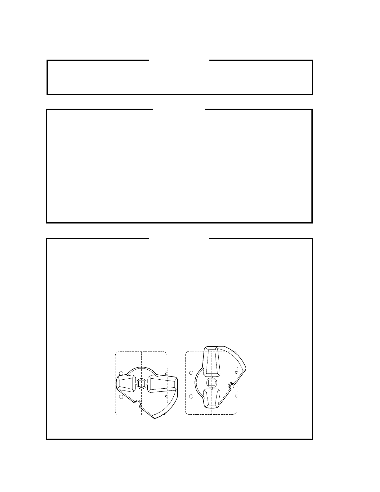
2. CLEANING
Ensure all components, fasteners and thumbscrews are securely in place
after any maintenance or cleaning is done to the equipment.
1. HOSHIZAKI recommends cleaning this unit at least once a year. More
frequent cleaning, however, may be required in some existing water
conditions.
2. To prevent injury to individuals and damage to the icemaker, do not use
ammonia type cleaners.
3. Always wear liquid-proof gloves for safe handling of the cleaning and
sanitizing solution. This will prevent irritation in case the solution comes
into contact with skin.
IMPORTANT
WARNING
IMPORTANT
1. The Cleaning Valve is used to allow solution flow to the inside of the
Evaporator during the cleaning and sanitizing operation. It should be
closed for all icemaking operation. The Compressor will not operate
unless this valve is completely closed.
2. To open the Cleaning Valve, the Valve Handle should be parallel to the
valve body. To close the valve, the Valve Handle should be at a right
angle to the valve body.
CLOSED POSITION
OPEN POSITION
70
Page 71

[a] CLEANING PROCEDURE
1) Dilute 16 fl. oz. of the recommended cleaner Hoshizaki “Scale Away” or
“LIME-A-WAY” (Economics Laboratory, Inc.) with 3 gallons of water.
2) Remove all ice from the Evaporator and the Storage Bin.
Note: To remove cubes on the Evaporator, turn off the power supply and turn
it on after 3 minutes. The defrost cycle starts and the cubes will be
removed from the Evaporator.
3) Turn off the power supply.
4) Remove the Front Panel and then remove the Insulation Panel.
5) Remove the Base Cover.
6) Drain the Water Tank by removing one end of the Pump Tubing. See Fig. 4.
7) After tank has drained, replace the removed parts in their correct positions.
8) Pour the cleaning solution into the Water Tank.
9) Fully open the Cleaning Valve on the left side wall of the machine compartment.
10) Move the Control Switch, on the Control Box, to the “WASH” position.
11) Replace the Insulation Panel and the Front Panel in their correct positions.
12) Turn on the power supply, and start the washing process.
13) Turn off the power supply after 30 minutes.
14) Remove the Front Panel and the Insulation Panel.
15) Drain the Water Tank. (See the above step 6).
16) Replace the tubing and the Insulation Panel in their correct positions.
17) Move the Control Switch to the “ICE” position.
18) Close the Cleaning Valve.
Note: The icemaker will not operate unless the Cleaning Valve is
completely closed.
19) Replace the Front Panel in its correct position.
71
Page 72

20) Turn on the power supply to fill the Water Tank with water.
21) Turn off the power supply after 3 minutes.
22) Remove the Front Panel, and fully open the Cleaning Valve.
23) Move the Control Switchto the “Wash” position.
24) Replace the Front Panel in its correct position.
25) Turn on the power supply to rise off the cleaning solution.
26) Turn off the power supply after 5 minutes.
27) Remove the Front Panel and Insulation Panel.
28) Drain the Water Tank by removing one end of the pump tuging. See Fig. 4.
After the tank has drained, replace the removed parts in their correct positions.
Note: Do not replace the Insulation Panel when you proceed to
“[b] SANITIZING PROCEDURE.’
29) Repeat the above steps 17) through 28) three more times to rinse thoroughly.
Note: If you do not sanitize the icemaker, go to step 9) in “[b] SANITIZING
PROCEDURE.”
[b] SANITIZING PROCEDURE - Following Cleaning Procedure
1) Dilute a 5.25% Sodium Hypochlorite solution (chlorine bleach) with water
(Add 1.5 fl. oz. of sanitizer to 3 gal. of water).
2) Remove the Insulation Panel, if it is in its normal position.
3) Pour the sanitizing solution into the Water Tank.
4) Replace the Insulation Panel and the Front Panel in their correct positions.
Note: Make sure that the Control Switch is in the “WASH” position and the
Cleaning Valve is open.
5) Turn on the power supply, and start the sanitizing process.
6) Turn off the power supply after 15 minutes.
7) Remove the Front Panel and if necessary, the Insulation Panel.
72
Page 73
8) Drain the Water Tank. See the above step 5) in “[a] CLEANING PROCEDURE.”
9) Replace the removed parts and the Insulation Panel in their correct positions.
10) Repeat the above steps 15) through 28) in “[a] CLEANING PROCEDURE” two
times to rinse thoroughly.
11) Close the Cleaning Valve.
12) Move the Control Switch to the “ICE” position.
13) Replace the Front Panel in its correct position.
14) Clean the Storage Bin with water.
15) Turn on the power supply, and start the automatic icemaking process.
3. MAINTENANCE
This icemaker must be maintained individually, referring to the instruction
manual and labels provided with the icemaker.
1) Stainless Steel Exterior
To prevent corrosion, wipe the exterior occasionally with a clean and soft cloth.
Use a damp cloth containing a neutral cleaner to wipe off oil or dirt build up.
2) Storage Bin and Scoop
• Wash your hands before removing ice. Use the plastic scoop provided.
• The Storage Bin is for ice use only. Do not store anything else in the bin.
• Keep the scoop clean. Clean it by using a neutral cleaner and rinse thoroughly.
• Clean the bin liner by using a neutral cleaner. Rinse thoroughly after cleaning.
IMPORTANT
3) Condenser (Except water-cooled model)
Check the Condenser once a year, and clean if required by using a brush or
vacuum cleaner. More frequent cleaning may be required depending on the
location of the icemaker.
73
 Loading...