

Page 1

Hoshizaki America, Inc.
Hoshizaki
Modular Crescent Cuber
Models
KM-515MAH
“A Superior Degree
of Reliability”
www.hoshizaki.com
KM-515MWH
KM-515MRH
PARTS LIST
Number: 71274
Issued: 1-28-2008
Revised: 8-3-2009
Page 2

CONTENTS
Auxiliary Codes ...................................................................................................................... 3
Note About Ordering Parts .................................................................................................... 3
Material Abbreviations ........................................................................................................... 4
A. Ice Cuber Assembly .......................................................................................................... 5
KM-515MAH ..................................................................................................................... 5
KM-515MWH ..................................................................................................................... 8
KM-515MRH .................................................................................................................... 10
B. Refrigeration Circuit ......................................................................................................... 12
KM-515MAH .................................................................................................................... 12
KM-515MWH ................................................................................................................... 16
KM-515MRH .................................................................................................................... 20
C. Water Circuit .................................................................................................................... 24
D. Control Box Assembly ...................................................................................................... 27
E. Label Location ................................................................................................................. 29
KM-515MAH .................................................................................................................... 29
KM-515MWH ................................................................................................................... 31
KM-515MRH .................................................................................................................... 33
F. Front Panel Assembly ....................................................................................................... 35
G. Top Panel Assembly ....................................................................................................... 36
H. Pump Motor Assembly..................................................................................................... 37
J. Control Assembly ............................................................................................................. 38
K. Accessories & Packaging ................................................................................................ 39
2
Page 3

Auxiliary Codes
KM-515MAH S-0 October 2007
T-0 April 2008
U-1 January 2009
U-2 February 2009
U-3 August 2009
KM-515MWH S-0 November 2007
T-0 February 2008
U-1 January 2009
U-2 February 2009
U-3 August 2009
KM-515MRH S-0 October 2007
T-0 May 2008
T-1 October 2008
U-1 January 2009
U-2 February 2009
U-3 August 2009
Auxiliary Code Breakdown
The auxiliary code is the rst two characters in the serial number. The rst character
indicates the year. Years progress or regress in alphabetical order. The series runs from
"A" through "V" and the letters "I" and "O" are skipped. The second character indicates
signicant part changes within a year. Base is "0" and this number advances for each
change. In cases where there is a letter in parentheses, this designates the month. This
is the last character in the serial number. The series runs from "(A)" through "(M)" and the
letter "(I)" is skipped. This designation is only included when identifying a parts change
within an auxiliary code.
Note About Ordering Parts
Most assemblies cannot be ordered as complete units; parts in the assemblies generally
must be ordered separately.
3
Page 4

Material Abbreviations
ALUMINUM
AL = Aluminum
COPPER
CU = Copper
PLASTIC
ABS = Acrylonitrile -butadiene - styrene
AC = Polyacetal
EVA = Ethylene vinyl acetate
PA = Polyamide = Nylon
PC = Polycarbonate
PE = Polyethylene
PES = Polyester
PETP = Polyethylene terephthalate = Tetlon
PP = Polypropylene
PS = Polystyrene
PTFE = Polytetrauoroethylene = Teon
PUR = Polyurethane
PVC = Polyvinyl chloride
RUBBER
VN = Vinyl Nitrile
EPDM = EP rubber
NBR = Nitrile butadiene rubber
NR = Natural rubber
NP = Neoprene
SI.R = Silicone rubber
SY.R = Synthetic rubber
EPH = Epichlorohydrin
STEEL
GS = Galvanized steel
SS = Stainless steel
PS = Plated steel
PAS = Primed steel
4
Page 5
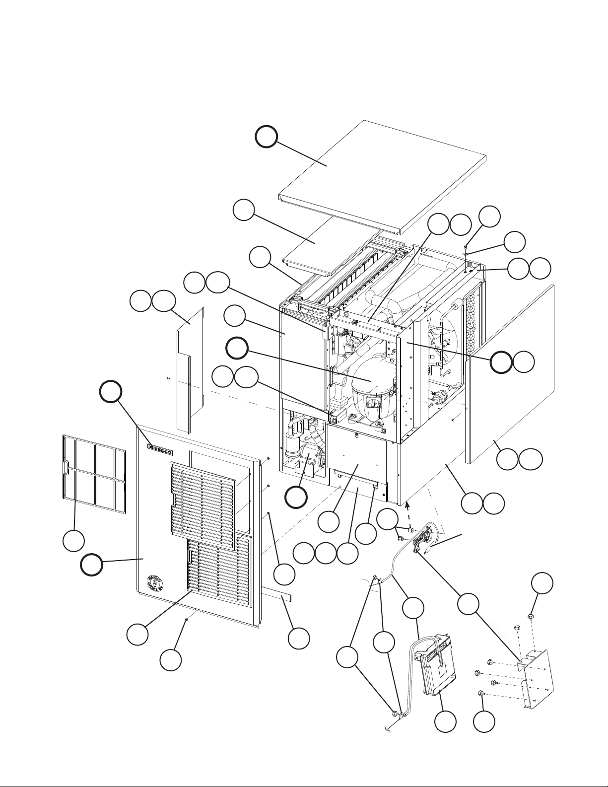
A. Ice Cuber Assembly
KM-515MAH
S-0 to U-3
G
E
15
15a
22
22a
19
13
B
12
19a
6
6a
1
5
4
7a
7
D1
D
14a
14
16
F
17
F1
18
C
21
2a
2
24
23
9
20
S-0 to U-1
25
For Thermostat, see
"D. Control Box
Assembly"
10
8
U-2 & later
10
11
3a
3
5
3b
10
Page 6

Title: A. Ice Cuber Assembly Model: KM-515MAH
S-0
T-0
Index
No. Description
B Refrigeration Circuit - 1A1406A01 1 -
C Water Circuit - 1A0283A05 1 1 1 1
D Control Box Assembly - 2A4374A01 1 1 -
D1 T2 Screw 4×8 7P31-0408 4 4 4 4
E Label Location - 3A4597A01 1 1 -
F Front Panel Assembly SS 2A3767G01 1 1 1 1
F1 Truss Head Screw 4×8, SS 7C32-0408 1 1 1 1
G Top Panel Assembly SS 3A3878A01 1 1 1 1
1 Evaporator Case - 1A0579G06 1 1 1 1
2 Base - 2A2146G12 1 1 -
2a FT Screw 4×8 7F31-0408 7 7 7 7
3 Frame - 3A2503G01 1 1 1 1
3a Truss Head Screw 4×8, SS 7C32-0408 1 1 1 1
3b Truss Head Screw 4×25, SS 7C32-0425 2 2 2 2
4 Square Washer BRASS 433537-02 1 1 1 1
5 Screw-Grounding BRASS 433304-02 1 1 1 1
6 Top Frame GS 3A3741-01 1 1 1 1
6a T2 Screw 4×8 7P31-0408 4 4 4 4
7 Side Frame GS 3A2782-01 1 1 1 1
7a T2 Screw 4×8 7P31-0408 2 2 2 2
8 Bulb Holder - 3A3903-01 1 1 -
Bin Control Switch Mount 3A4463-01 1 1
9 Strap - 435487-01 1 1 1 1
10 Thumbscrew SS, ABS 415949G10 1 1 7 7
11 Base Cover SS 321525G01 1 1 1 1
12 Top Insulation PP 215730G01 1 1 1 1
13 Front Insulation PP 215731G01 1 1 1 1
14 Side Panel (R) SS 2A2117G01 1 1 1 1
14a T2 Screw 4×8, SS 7P32-0408 1 1 1 1
15 Control Box Cover GS 3A2476-01 1 1 1 1
15a T2 Screw 4×8 7P31-0408 1 1 1 1
16 Air Filter (A) ABS 2A2062G01 2 2 2 2
17 Louver (A) ABS 1A0547-01 2 2 2 2
18 Push Retainer - 4A2414-01 6 6 6 6
19 Barrier GS 4A0362-01 1 1 1 1
19a T2 Screw 4×8 7P31-0408 2 2 2 2
20 Silicone Hose L=380 7730I3812 1 1 -
21 Gasket L=554 4A0808L02 1 1 1 1
22 Barrier-Insulation GS 4A1167-01 1 1 1 1
22a T2 Screw 4×8 7P31-0408 2 2 2 2
Material or
Model Number Part Number
1A1639A01 1 1 1
2A4374A03 1 1
3A5038A01 1 3A5561A01 1
2A4319G07 1 1
L=325 7730-1114 1 -
T- 0
(M)
(A-L)
U-1 U-2 U-3
Required Number
6
Page 7

Title: A. Ice Cuber Assembly Model: KM-515MAH
S-0
T-0
Index
No. Description
23 Thumbscrew SS, ABS 415949G11 2 2 24 Capillary Ring - 425307-01 1 1 1 -
25 Bin Control - 2A4393G01 1 1
Material or
Model Number Part Number
425307-02 1
T- 0
(M)
(A-L)
U-1 U-2 U-3
Required Number
7
Page 8
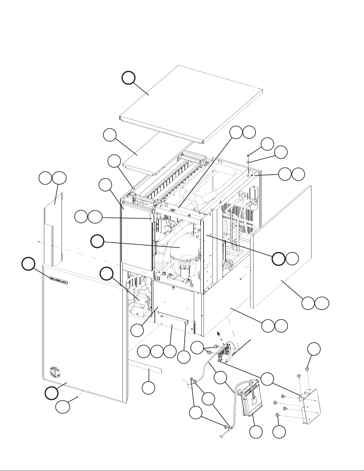
A. Ice Cuber Assembly
KM-515MWH
S-0 to U-3
12
1
15a
15
13
G
6a
6
5
4
7a
7
E
F
F1
17
17a
B
C
11
3
16
3a 3b
20
19
10
18
D1
D
14a
14
2a
2
For Thermostat, see
"D. Control Box
Assembly"
S-0 to U-1
9
8
U-2 & later
10
21
8
10
Page 9

Title: A. Ice Cuber Assembly Model: KM-515MWH
S-0
T-0
Index
No. Description
B Refrigeration Circuit - 1A1408A01 1 -
C Water Circuit - 1A0283A05 1 1 1 1
D Control Box Assembly - 2A4374A02 1 1 -
D1 T2 Screw 4×8 7P31-0408 4 4 4 4
E Label Location - 3A4598A01 1 1 -
F Front Panel Assembly SS 2A2150G01 1 1 1 1
F1 Truss Head Screw 4×8, SS 7C32-0408 1 1 1 1
G Top Panel Assembly SS 3A3878A01 1 1 1 1
1 Evaporator Case - 1A0579G06 1
2 Base - 2A2146G17 1 1 -
2a FT Screw 4×8 7F31-0408 7 7 7 7
3 Frame - 3A2503G01 1 1 1 1
3a Truss Head Screw 4×8, SS 7C32-0408 1 1 1 1
3b Truss Head Screw 4×25, SS 7C32-0425 2 2 2 2
4 Square Washer BRASS 433537-02 1 1 1 1
5 Screw-Grounding BRASS 433304-02 1 1 1 1
6 Top Frame GS 3A3741-01 1 1 1 1
6a T2 Screw 4×8 7P31-0408 4 4 4 4
7 Side Frame GS 3A2782-01 1 1 1 1
7a T2 Screw 4×8 7P31-0408 2 2 2 2
8 Bulb Holder - 3A3903-01 1 1 -
Bin Control Switch Mount 3A4463-01 1 1
9 Silicone Hose L=380 7730I3812 1 1 -
10 Thumbscrew SS, ABS 415949G10 1 1 7 7
11 Base Cover SS 321525G01 1 1 1 1
12 Top Insulation PP 215730G01 1 1 1 1
13 Front Insulation PP 215731G01 1 1 1 1
14 Side Panel (R) SS 2A2117G01 1 1 1 1
14a T2 Screw 4×8, SS 7P32-0408 1 1 1 1
15 Control Box Cover GS 3A2476-01 1 1 1 1
15a T2 Screw 4×8 7P31-0408 1 1 1 1
16 Gasket L=554 4A0808L02 1 1 1 1
17 Barrier-Insulation GS 4A1167-01 1 1 1 1
17a T2 Screw 4×8 7P31-0408 2 2 2 2
18 Strap - 435487-01 1 1 1 1
19 Thumbscrew SS, ABS 415949G11 2 2 20 Capillary Ring - 425307-01 1 1 1 -
21 Bin Control - 2A4393G01 1 1
Material or
Model Number Part Number
1A1640A01 1 1 1
2A4374A04 1 1
3A5040A01 1 3A5562A01 1
2A4319G11 1 1
L=325 7730-1114 1 -
425307-02 1
T- 0
(M)
(A-L)
U-1 U-2 U-3
Required Number
9
Page 10
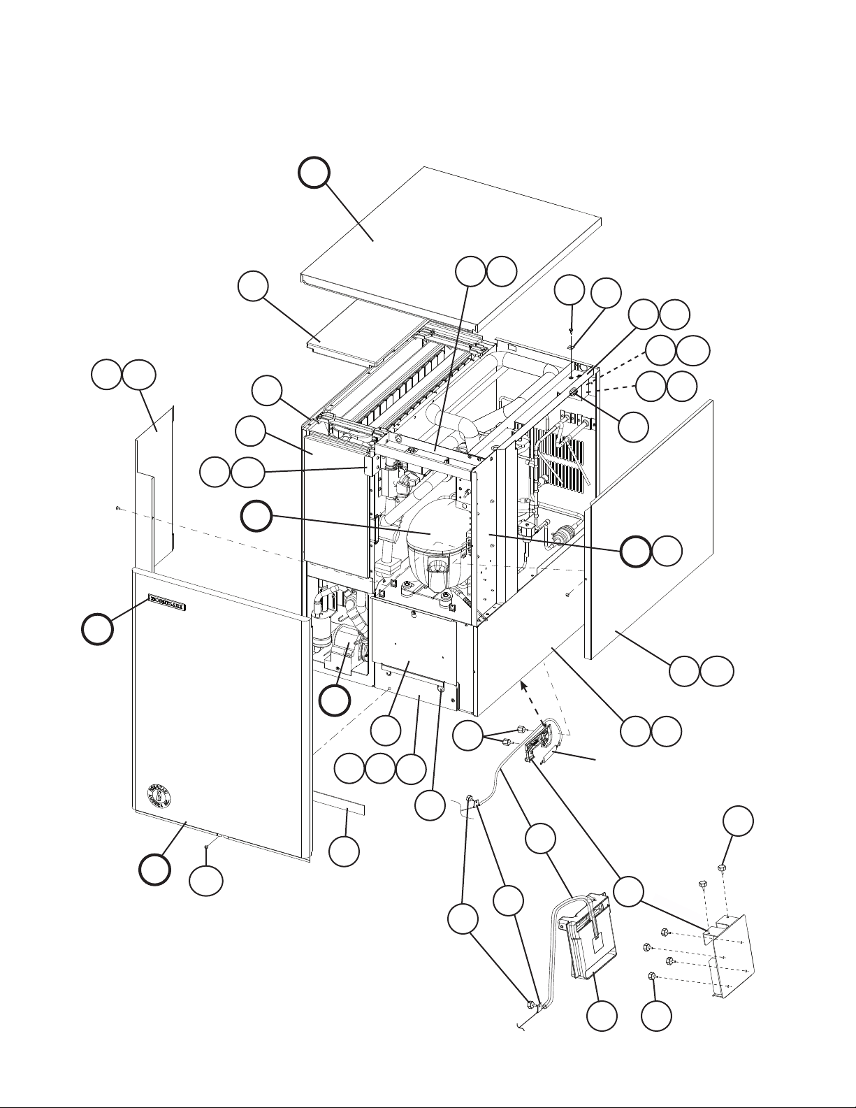
A. Ice Cuber Assembly
KM-515MRH
S-0 to U-3
12
15a
15
1
G
6a
6
5
4
7a
7
18a
18
54
E
F
F1
19
13
19a
B
C
16
20
D1
D
14a
14
11
3a
3
3b
22
21
10
For Thermostat, see
"D. Control Box
Assembly"
S-0 to U-1
17
9
2
8
2a
10
U-2 & later
10
23
10
Page 11
Title: A. Ice Cuber Assembly Model: KM-515MRH
S-0
Index
No. Description
B Refrigeration Circuit - 1A1410A01 1 -
C Water Circuit - 1A0283A05 1 1 1 1
D Control Box Assembly - 2A4374A02 1 1 -
D1 T2 Screw 4×8 7P31-0408 4 4 4 4
E Label Location - 3A4599A01 1 1 -
F Front Panel Assembly SS 2A2150G01 1 1 1 1
F1 Truss Head Screw 4×8, SS 7C32-0408 1 1 1 1
G Top Panel Assembly SS 3A3878A01 1 1 1 1
1 Evaporator Case - 1A0579G06 1 1 1 1
2 Base - 2A2146G14 1 1 -
2a FT Screw 4×8 7F31-0408 7 7 7 7
3 Frame - 3A2503G01 1 1 1 1
3a Truss Head Screw 4×8, SS 7C32-0408 1 1 1 1
3b Truss Head Screw 4×25, SS 7C32-0425 2 2 2 2
4 Square Washer BRASS 433537-02 2 2 2 2
5 Screw-Grounding BRASS 433304-02 2 2 2 2
6 Top Frame GS 3A3741-01 1 1 1 1
6a T2 Screw 4×8 7P31-0408 4 4 4 4
7 Side Frame GS 3A2782-01 1 1 1 1
7a T2 Screw 4×8 7P31-0408 2 2 2 2
8 Bulb Holder - 3A3903-01 1 1 -
Bin Control Switch Mount 3A4463-01 1 1
9 Strap - 435487-01 1 1 1 1
10 Thumbscrew SS, ABS 415949G10 1 1 7 7
11 Base Cover SS 321525G01 1 1 1 1
12 Top Insulation PP 215730G01 1 1 1 1
13 Front Insulation PP 215731G01 1 1 1 1
14 Side Panel (R) SS 2A2117G01 1 1 1 1
14a T2 Screw 4×8, SS 7P32-0408 1 1 1 1
15 Control Box Cover - 3A2476-01 1 1 1 1
15a T2 Screw 4×8 7P31-0408 1 1 1 1
16 Gasket L=554 4A0808L02 1 1 1 1
17 Silicone Hose L=380 7730I3812 1 1 -
18 Junction Box Cover GS 433410-01 1 1 1 1
18a T2 Screw 4×8 7P31-0408 1 1 1 1
19 Barrier-Insulation GS 4A1167-01 1 1 1 1
19a T2 Screw 4×8 7P31-0408 2 2 2 2
20 Bushing SR-30-1 420472-03 1 1 1 1
21 Thumbscrew SS, ABS 415949G11 2 2 22 Capillary Ring - 425307-01 1 1 1 -
23 Bin Control - 2A4393G01 1 1
Material or
Model Number Part Number
1A1641A01 1 1 1
2A4374A04 1 1
3A5047A01 1 3A5563A01 1
2A4319G12 1 1
L=325 7730-1114 1 -
425307-02 1
to
T- 1 U-1 U-2 U-3
Required Number
11
Page 12
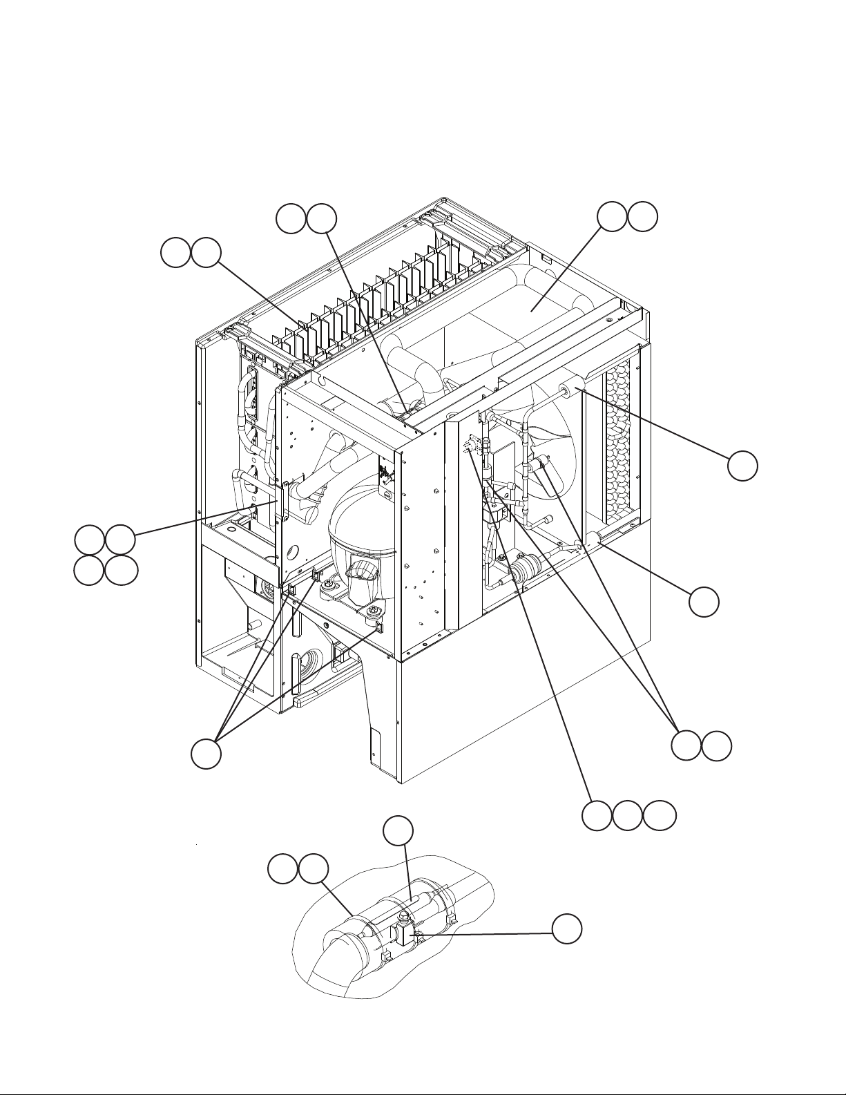
B. Refrigeration Circuit
1/2
KM-515MAH
S-0 to U-3
4a
4
32 45
2a
2
42
37
39
38
39a
44
43
45
30
S-0 to T-0 (L)
31
16
17
S-0 to T-0 (L)
40
17a
41
45
Detailed TXV Bulb Attachment
12
Page 13

B. Refrigeration Circuit
2/2
KM-515MAH
S-0 to U-3
29
28
20
4540
14
13
15
26
15a
24
15b
27
19
S-0 to T-0 (L)
18
10
3a
3
1a
1
9a
9
18
8a
8
23
21
20
5
5a
5c5b
6
7
22
25
15
15a
11 12
15b
46
46a
T-0 (M) & later
45
T-0 (M) & later
34
20
16
36
35
Detailed Thermistor Attachment
33
4540
13
Page 14

Title: B. Refrigeration Circuit Model: KM-515MAH
S-0
Inde×
No. Description
Material or
Model Number Part Number
T- 0
(A-L)
1 Condenser - 2A3756-01 1 1
1a T2 Screw 4×8 7P31-0408 2 2
2 Shroud GS 2A3760-01 1 1
2a T2 Screw 4×8 7P31-0408 5 5
3 Barrier GS 433693-04 1 1
3a T2 Screw 4×8 7P31-0408 2 2
4 Evaporator - 106492G01 1 1
4a T2 Screw 4×16, SS 7P32-0416 4 4
5 Compressor
RST55C1ECAA-202
4A4376-01 1 1
5a Bolt 8×45 437889-01 4 4
5b Spacer - 4A2595-01 4 4
5c Grommet - 4A2593-01 4 4
6 Protector - 4A2634-02 1 1
7 Valve Body-Liquid Line - 4A3276-01 1 1
8 Fan Motor Bracket GS 3A3859-01 1 1
8a Hex Head Bolt W/Washer (LF) 5×12 7B0130512 4 4
9 Fan Motor
5KCP84DFK148S
4A3158-01 1 1
9a Self-locking Nut NO. 8-32 7N21I0832 4 4
10 Fan Blade AD10EECW40 4A3959-01 1 1
11 Drier C-03E117 4A2666-01 1 1
12 Nylon Tie - 8911-0301 1 1
13 Expansion Valve
HFE-10NHDU-4
4A4008-01 1 1
14 Valve Body-Hot Gas - 4A3978-01 1 1
15 Coil-Valve 4A3277-01 2 2
15a Bolt 4×6 4A3277F01 2 2
15b Truss Head Screw 4×8 7C31-0408 4 4
16 Pressure Switch ACB-1UB09 433441-07 1 -
ACB-1UB44 463180-04 1
17 Pressure Switch Bracket - 434938-01 1 17a T2 Screw 4×8 7P31-0408 1 -
18 Gasket L=245 4A0808L02 2 2
19 Copper Tube Access Valve COPPER 3A3999G01 1 1
20 Access Valve - 457729-01 2 2
21 Copper Tube (A)-High Side COPPER 2A4385G02 1 -
2A4808G2 1
22 Copper Tube (B)-High Side COPPER 4A3962-01 1 1
23 Copper Tube (C)-High Side COPPER 4A3961-01 1 1
24 Copper Tube (D)-High Side COPPER 3A3855G01 1 1
25 Copper Tube (E)-High Side COPPER 3A3905-01 1 1
26 Strainer (included in item
-
441569-01 1 1
24: 3A3855G01)
27 Heat Exchanger - 2A4382G01 1 1
28 Elbow COPPER 417395-03 1 1
29 Copper Tube-Hot Gas COPPER 2A4099G01 1 1
30 Holder/Expansion Valve-3/8 SS 3A0107-01 1 1
31 Clamp SS 443461-02 1 1
Required Number
T-0
(M)
to
U-3
14
Page 15

Title: B. Refrigeration Circuit Model: KM-515MAH
S-0
Inde×
No. Description
32 Expansion Valve Cover PE FOAM 3A0944-01 1 1
33 Thermistor - 429006-03 1 1
34 Holder-Thermistor COPPER 427430-01 1 1
35 Insulation-Thermistor (A) PE FOAM 439368-01 1 1
36 Insulation-Thermistor (B) PE FOAM 439368-02 1 1
37 Rubber Insulation (A) EPDM 3A1044-01 1 1
38 Rubber Insulation (B) EPDM 3A1045-01 1 1
39 Insulation Holder - 4A1550-01 1 1
39a T2 Screw 4×8, SS 7P32-0408 2 2
40 Insulation Tube L=40 7762-1020 4 3
41 Insulation Tube L=40 7762-1030 1 1
42 Insulation Tube L=40 7762-1630 1 1
43 Insulation Tube L=150 7762-2943 1 1
44 Wire Saddle VWS4238-C 4A0338-02 8 8
45 Cable Tie CV-200 (PLT-
46 Line Valve Bracket - 4A4011-01 1 1
46a T2 Screw 4×8 7P31-0408 2 2
Material or
Model Number Part Number
8911-0200 14 13
2M)
T- 0
(A-L)
Required Number
T-0
(M)
to
U-3
15
Page 16

B. Refrigeration Circuit
1/2
KM-515MWH
S-0 to U-3
8a
8
42
43
12
39
44
44a
S-0 to T-0 (L)
S-0 to T-0 (L)
12
41
4
15
15a
14
12
40
37
38
Detailed TXV Bulb Attachment
16
Page 17

B. Refrigeration Circuit
2/2
KM-515MWH
S-0 to U-3
11
13
13a
13b
31
5a
5
1a
1
18a
18
36
26
12
28
41
27
30
2923
21
16
17
17a
19
45
12
41
S-0 to T-0 (L)
28
22
2
2a 2b
2c
3
20
T-0 (M) & later
13b
14
35
25
12
24
9 13
33
32
10
7
6
10a
T-0 (M) & later
28
13a
34
Detailed Thermistor Attachment
4112
17
Page 18

Title: B. Refrigeration Circuit Model: KM-515MWH
S-0
Index
No. Description
Material or
Model Number Part Number
T- 0
(A-L)
1 Rear Panel GS 2A1426-01 1 1
1a T2 Screw 4×8 7P31-0408 5 5
2 Compressor
RST55C1E-CAA
4A4376-01 1 1
2a Bolt 8×45 437889-01 4 4
2b Spacer - 4A2595-01 4 4
2c Grommet - 4A2593-01 4 4
3 Protector - 4A2634-02 1 1
4 Wire Saddle - 4A0338-02 8 8
5 Condenser-Water-Cooled HS-0160 2A2359G01 1 1
5a Hex Head Bolt W/Washer (LF) 5×10 7B0130510 2 2
6 Drier C-03E117 4A2666-01 1 1
7 Nylon Tie NYLON 8911-0301 1 1
8 Evaporator - 106492G01 1 1
8a T2 Screw 4×16, SS 7P32-0416 4 4
9 Valve Body-Liquid Line - 4A3276-01 1 1
10 Valve Bracket - 436893-01 1 1
10a T2 Screw 4×8 7P31-0408 2 2
11 Valve Body-Hot Gas - 4A3978-01 1 1
12 Cable Tie PLT-2M 8911-0200 15 14
13 Coil-Valve
AMS-C12HDU-3
4A3277-01 2 2
13a Bolt - 4A3277F01 2 2
13b Truss Head Screw 4×8 7C31-0408 4 4
14 Pressure Switch ACB-2UB04 433441-05 1 -
ACB-1UB43 463180-05 1
15 Pressure Switch Bracket GS 434938-01 1 -
15a T2 Screw 4×8 7P31-0408 1 -
16 Male Connector - 4A1087-01 1 1
17 Water Regulator V46DA-6 4A0911-06 1 1
17a Truss Head Screw 4×6 7C31-0406 2 2
18 Copper Tube (A)-Water Circuit COPPER 3A1251G01 1 1
18a T2 Screw 4×8 7P31-0408 2 2
19 Copper Tube (B)-Water Circuit COPPER 4A2681G01 1 1
20 Copper Tube (A)-High Side COPPER 2A4385G02 1 -
2A4808G02 1
21 Copper Tube (B)-High Side COPPER 3A2219-01 1 1
22 Copper Tube (C)-High Side COPPER 4A2682G01 1 1
23 Copper Tube (D)-High Side COPPER 3A3855G01 1 1
24 Copper Tube (E)-High Side COPPER 3A3541-01 1 1
25 Copper Tube (F)-High Side COPPER 4A3971-01 1 1
26 Copper Tube-Hot Gas COPPER 2A4387G01 1 1
27 Copper Tube-Access Valve - 3A3999G01 1 1
28 Access Valve
29 Strainer (Included in item
TCJ-2F20NHDU-1
-
457729-01 2 2
441569-01 1 1
23: 3A3855G01)
30 Expansion Valve
HFE-10NHDU-4
4A4008-01 1 1
Required Number
T-0
(M)
to
U-3
18
Page 19

Title: B. Refrigeration Circuit Model: KM-515MWH
S-0
Index
No. Description
31 Heat Exchanger - 2A4382G01 1 1
32 Thermistor - 429006-03 1 1
33 Holder-Thermistor - 427430-01 1 1
34 Insulation-Thermistor (A) PE FOAM 439368-01 1 1
35 Insulation-Thermistor (B) PE FOAM 439368-02 1 1
36 Elbow COPPER 417395-03 1 1
37 Holder/Expansion Valve-3/8 - 3A0107-01 1 1
38 Clamp SS 443461-02 1 1
39 Expansion Valve Cover PE FOAM 3A0944-01 1 1
40 Insulation Tube L=150 7762-2943 1 1
41 Insulation Tube L=40 7762-1020 5 4
42 Rubber Insulation (A) EPDM 3A1044-01 1 1
43 Rubber Insulation (B) EPDM 3A1045-01 1 1
44 Insulation Holder - 4A1550-01 1 1
44a T2 Screw 4×8, SS 7P32-0408 2 2
45 Elbow - 417395-02 1 1
Material or
Model Number Part Number
T- 0
(A-L)
Required Number
T-0
(M)
to
U-3
19
Page 20

B. Refrigeration Circuit
1/2
KM-515MRH
S-0 to U-3
38 47
15a
15
43
45
44
45a
35
S-0 to T-1
S-0 to T-1
47
46
17
17a
16
4
37
47
36
Detailed TXV Bulb Attachment
20
Page 21

B. Refrigeration Circuit
2/2
KM-515MRH
S-0 to U-3
20a
19
20
20b
34
1a
1
28
8
10
8a
10a
25
7
29
9
14
30
23
32
33
11a
11
46 47
31
26
S-0 to T-1
2a
2
2b
2c
2d
27
12
22
13
41
42
3
6
5
47
Detailed Thermistor Attachment
21
40
24
39
18
18a
20a
20
U-1 & later
16
20b
U-1 & later
21
4746
Page 22

Title: B. Refrigeration Circuit Model: KM-515MRH
Index
No. Description
Material or
Model Number Part Number
S-0
T- 0 T- 1
1 Rear Panel GS 220468G03 1 1 1
1a T2 Screw 4×8 7P31-0408 5 5 5
2 Compressor
RST55C1ECAA-202
4A4376-01 1 1 1
2a Bolt 8×45 437889-01 4 4 4
2b Spacer - 4A2595-01 4 4 4
2c Grommet - 4A2593-01 4 4 4
2d Washer - 4A4409-01 4 -
3 Protector - 4A2634-02 1 1 1
4 Wire Saddle VWS4238-C 4A0338-02 9 9 9
5 Crankcase Heater - 3A4663-01 1 1 1
6 Retainer - 4A4412-01 1 1 1
7 Coupling - 4A3972G01 1 1 1
8 Tube Holder-S - 438246-01 1 1 1
8a T2 Screw 4×8 7P31-0408 2 2 2
9 Coupling - 434136G01 1 1 1
10 Tube Holder-L - 438245-01 1 1 1
10a T2 Screw 4×8 7P31-0408 2 2 2
11 Receiver Tank RR KN WP450 437596-01 1 1 1
11a Hex Head Bolt W/Washer (LF) 5×10, SS 7B0130510 3 3 3
12 Drier C-03E117 4A2666-01 1 1 1
13 Nylon Tie - 8911-0301 1 1 1
14 Expansion Valve
HFE-10NHD-2
4A1414-01 1 1 1
15 Evaporator - 106492G01 1 1 1
15a T2 Screw 4×16, SS 7P32-0416 4 4 4
16 Pressure Switch ACB-1UB09 433441-07 1 1 -
ACB-1UB44 463180-04 1
17 Pressure Switch Bracket GS 434938-01 1 1 -
17a T2 Screw 4×8 7P31-0408 1 1 -
18 Valve Bracket - 436893-01 1 1 1
18a T2 Screw 4×8 7P31-0408 2 2 2
19 Valve Body-Hot Gas 70 4A3978-01 1 1 1
20 Coil-Valve
AMS-C12HDU-3
4A3277-01 2 2 2
20a Bolt 4×6 4A3277F01 2 2 2
20b Truss Head Screw 4×8 7C31-0408 4 4 4
21 Valve Body-Liquid Line - 4A3276-01 1 1 1
22 Copper Tube (A)-High Side COPPER 2A4385G01 1 1 -
2A4808G01 1
23 Copper Tube (B)-High Side COPPER 3A3867G01 1 1 1
24 Copper Tube (C)-High Side COPPER 3A3973-01 1 1 1
25 Copper Tube (D)-High Side COPPER 3A3855G01 1 1 1
26 Copper Tube (E)-High Side COPPER 332445-01 1 1 1
27 Copper Tube (F)-High Side COPPER 4A2768-01 1 1 1
28 Copper Tube (G)-High Side COPPER 3A3868G01 1 1 1
29 Strainer (Included in item 25:
- 441569-01 1 1 1
3A3855G01)
Required Number
U-1
to
U-3
22
Page 23

Title: B. Refrigeration Circuit Model: KM-515MRH
Index
No. Description
30 Copper Tube-Hot Gas COPPER 2A4400G01 1 1 1
31 Copper Tube-Access Valve COPPER 3A3999G01 1 1 1
32 Access Valve - 457729-01 1 1 1
33 Elbow COPPER 417395-03 1 1 1
34 Heat Exchanger - 2A4382G01 1 1 1
35 Holder-Expansion Valve-3/8 SS 3A0107-01 1 1 1
36 Clamp - 443461-02 1 1 1
37 Insulation Tube L=150 7762-2943 1 1 1
38 Expansion Valve Cover PE FOAM 3A0944-01 1 1 1
39 Thermistor - 429006-03 1 1 1
40 Holder-Thermistor COPPER 427430-01 1 1 1
41 Insulation-Thermistor (A) PE FOAM 439368-01 1 1 1
42 Insulation-Thermistor (B) PE FOAM 439368-02 1 1 1
43 Rubber Insulation (A) EPDM 3A1044-01 1 1 1
44 Rubber Insulation (B) EPDM 3A1045-01 1 1 1
45 Insulation Holder - 4A1550-01 1 1 1
45a T2 Screw 4×8, SS 7P32-0408 2 2 2
46 Insulation Tube L=40 7762-1020 3 3 3
47 Cable Tie - 8911-0200 13 13 13
Material or
Model Number Part Number
S-0
T- 0 T- 1
Required Number
U-1
to
U-3
23
Page 24

C. Water Circuit
KM-515MAH, KM-515MWH, KM-515MRH
S-0 to U-3
6
5
13
26
4
45
7
47
27
1a
1
44
29
13
24
42
15
15a
23a
23
22
10
13
13
37
16
H
28
17
12
14
46
40
38
39
11
30
41
43
H2
36
35
H3
18
H4
33
32
9
2
3
34
21
32a
31
19
20
3a
31a
8
25
10a
H1
24
Page 25

Title: C. Water Circuit Model: KM-515MAH, KM-515MWH, KM-515MRH
S-0
Index
No. Description
H Pump Motor Assembly HS-0176 3A2638A03 1
H1 Truss Head Screw 4×16, SS 7C32-0416 1
H2 Flat Washer M4, SS 7W22-0400 1
H3 Split Lock Washer M4, SS 7L22-0400 1
H4 Hex Nut M4, SS 7N12-0400 1
1 Water Supply Pipe COPPER 4A0768G04 1
1a T2 Screw 4×8 7P31-0408 2
2 Rubber Gasket NR 413854-03 1
3 Water Valve Bracket GS 321443-01 1
3a T2 Screw 4×8 7P31-0408 1
4 Water Valve J248-072 3U0111-04 1
5 Hose Clamp SS, 18MM 427443-05 1
6 Spray Tube PE 1A0260-02 1
7 Spray Guide (A) PE 208586-01 6
8 Cube Guide ABS 212088-01 1
9 Suction Hose EPDM 433466-01 1
10 Pump Motor Bracket PC 211408-01 1
10a Flat Head Screw 4×12, SS 7F32-0412 1
11 Vinyl Hose L=250 7716-2025 1
12 Vinyl Hose L=110 7716-2025 1
13 Hose Clamp SS, 25MM 427443-03 9
14 "O" Ring 1AG35 7611-G035 1
15 Valve Housing-Drain ABS 321001-01 1
15a T2 Screw 4×10, SS 7P32-0410 3
16 Spring SS 322110-01 1
17 Valve Seat EPDM 433705-01 1
18 Drain Hose SANTO-
19 Overow Cap PE 321002-01 1
20 Overow Pipe ABS 430722-03 1
21 "O" Ring EPDM 4A1234-01 1
22 Connector-Float Switch EPDM 426799-01 1
23 Float Switch - 4A3624-01 1
23a T2 Screw 4×12, SS 7P32-0412 2
24 Silicone Hose L=140 7730I3896 1
25 Wire Saddle VWS4238-C 4A0338-02 4
26 Te e SANTO-
27 Bushing OCB-750 428394-01 1
28 Flange EPDM 439267-01 1
29 Distributor EPDM 432426-01 1
30 Rubber Ring EPDM 439236-01 1
31 Handle JH1352 215383-01 1
31a T2 Screw 4×8 7P31-0408 1
32 Valve Holder GS 3A1178-01 1
32a FT Screw 4×8 7F31-0408 3
Material or
Model Number Part Number
433468-01 1
PRENE
4A0177-01 1
PRENE
to
U-3
Required Number
25
Page 26

Title: C. Water Circuit Model: KM-515MAH, KM-515MWH, KM-515MRH
S-0
Index
No. Description
33 Microswitch - 4A2546-01 1
34 Tapping Screw 3×14 431415-02 2
35 Corner Insulation (A) PE FOAM 439376-01 1
36 Corner Insulation (B) PE FOAM 439392-01 1
37 Hose Clamp SS, 20 MM 427443-06 1
38 Ball Valve (Included in S-0761) PVC 439293-01 1
39 Male Adaptor (Included in
S-0761)
40 "O" Ring (Included in S-0761) 1AP18 7611-P018 2
41 Insulation Tube L=190 7762-2636 1
42 Silicone Hose L=140 7730I3812 1
43 Rubber Hose (D) EPDM 4A1551-04 1
44 Rubber Hose (C) SANTO-
45 Plug EPDM 4A0176-01 2
46 Insulation (E) PE FOAM 4A0392-01 1
47 Water Supply Tube PE 2A0079-01 1
Material or
Model Number Part Number
ABS 325826-01 2
4A1551-03 1
PRENE
U-3
to
Required Number
26
Page 27

D. Control Box Assembly
KM-515MAH, KM-515MWH, KM-515MRH
S-0 to U-3
12
13
7
J1
J
15
5a
5
6a
6
10 11
9a
9
8a
8
15a
14
16
3
4a
4
2
27
1
Page 28

Title: D. Control Box Assembly Model: KM-515MAH, KM-515MWH, KM-515MRH
S-0
Index
No. Description
J Control Assembly - 4A2911A01 1 -
J1 T2 Screw 4×8 7P31-0408 2 2
1 Control Box - 2A1851-01 1 -
2 Capacitor-Run 35MFD,
3 Capacitor-Starting 243-292MFD,
4 Strap GS 4A2262-03 1 1
4a T2 Screw 4×8 7P31-0408 1 1
5 Starter 3ARR3CT5M5 4A1107-11 1 1
5a T2 Screw 4×8 7P31-0408 1 1
6 Magnetic Contactor VC-20 428393-01 1 1
6a T2 Screw 4×8 7P31-0408 2 2
7 Fuse (Spare) - 4A0893-07 1 1
8 Transformer 26D285H 3A0172-01 1 1
8a T2 Screw 4×8 7P31-0408 2 2
9 Capacitor-Pump Motor 5.5MFD,
9a T2 Screw 4×10 7P31-0410 1 1
10 Control Board "E" Board 2A1410-01 1 -
11 Board Support CBLS37-M 4A0336-03 4 4
12 Bushing SB-1093-15 420470-03 1 1
13 Bushing OCB-500 428394-02 1 1
14 Clamp - 4A2338-01 2 2
15 Capacitor-Fan Motor KM-515MAH
15a T2 Screw KM-515MAH
16 Wire Harness - 4A2200G04 1
Material or
Model Number Part Number
4A4612A01 1
2A4865-01 1
3A2005-12 1 1
440VAC
3A0076-20 1 1
165V
443192-03 1 1
250VAC
"G" Board 2A3792-01 1
443192-02 1 1
5MFD,
250VAC
7P31-0410 1 1
4×10
to
U-1
U-2
U-3
Required Number
28
Page 29

E. Label Location
KM-515MAH
S-0 to U-3
15
9
6
4
17
14
1
7
3
11
12
10
13
5
16
18
8
2
29
Control Box
Page 30

Title: E. Label Location Model: KM-515MAH
S-0
Index
No. Description
1 Emblem PETP FILM 4A0560-01 1 1 1
2 Label-Alarm - 4A3517-01 1 1 -
3 Label-Penguin-HA (R) PETP FILM 4A0526-01 1 1 1
4 Maintenance Label PVC FILM 3A4649-01 1 1 -
5 Wiring Label PVC FILM 3A4595-01 1 -
6 Nameplate PES FILM 2A4372-01 1 1 1
7 Instruction Sheet PAPER 2A4371-01 1 -
8 Manual Label PVC FILM 446564-01 1 -
9 Tag-Warning: Electrical
Connection
10 Operation Label-Valve PVC FILM 439541-01 1 1 -
11 Label-R404A PES FILM 4A0960-01 1 1 1
12 Caution Label (F) PVC FILM 439146-01 1 1 -
Warning Label (F) 4A4767-01 1
13 Caution Label (H) PVC FILM 439148-01 1 1 -
Warning Label (H) 4A4795-01 1
14 Label-Air Filter PETP FILM 426177-01 1 1 1
15 Instruction Label PVC FILM 444575-01 1 1 1
16 Label-Control Board PVC FILM 3A2220-01 1 -
17 Rating Label - 2A4373-01 1 1 1
18 Label-Fuse - 4A2817-01 1 1 -
Material or
Model Number Part Number
4A4737-01 1
3A5404-01 1
3A5036-01 1 1
4A4615-01 1 1
PAPER 435005-01 1 1 -
4A4766-01 1
4A4828-01 1
3A4799-01 1 1
4A4829-01 1
to
U-1 U-2 U-3
Required Number
30
Page 31

E. Label Location
KM-515MWH
S-0 to U-3
13
9
6
4
15
11
1
7
10
3
12
5
14
16
8
2
31
Control Box
Page 32

Title: E. Label Location Model: KM-515MWH
S-0
Index
No. Description
1 Emblem PETP FILM 4A0560-01 1 1 1
2 Label-Alarm - 4A3517-01 1 1 -
3 Label-Penguin-HA (R) PETP FILM 4A0526-01 1 1 1
4 Maintenance Label PVC FILM 3A4649-01 1 1 -
5 Wiring Label PVC FILM 3A4595-01 1 -
6 Nameplate PES FILM 2A4372-02 1 1 1
7 Instruction Sheet PAPER 2A4371-01 1 -
8 Manual Label PVC FILM 446564-01 1 -
9 Tag-Warning: Electrical
Connection
10 Operation Label-Valve PVC FILM 439541-01 1 1 -
11 Label-R404A PES FILM 4A0960-01 1 1 1
12 Caution Label (H) PVC FILM 439148-01 1 1 -
Warning Label (H) 4A4795-01 1
13 Instruction Label PVC FILM 444575-01 1 1 1
14 Label-Control Board PVC FILM 3A2220-01 1 -
15 Rating Label - 2A4373-02 1 1 1
16 Label-Fuse - 4A2817-01 1 1 -
Material or
Model Number Part Number
4A4737-01 1
3A5404-01 1
3A5036-01 1 1
4A4615-01 1 1
PAPER 435005-01 1 1 -
4A4766-01 1
4A4828-01 1
3A4799-01 1 1
4A4829-01 1
to
U-1 U-2 U-3
Required Number
32
Page 33

E. Label Location
KM-515MRH
S-0 to U-3
17
18
11
13
9
1
6
4
15
11
7
10
3
12
2
5
8
14
16
Control Box
33
Page 34

Title: E. Label Location Model: KM-515MRH
S-0
Index
No. Description
1 Emblem PETP FILM 4A0560-01 1 1 1
2 Label-Fuse - 4A2817-01 1 1 -
3 Label-Penguin-HA (R) PETP FILM 4A0526-01 1 1 1
4 Maintenance Label PVC FILM 3A4649-01 1 1 -
5 Wiring Label PVC FILM 3A4596-01 1 -
6 Nameplate PES FILM 2A4372-03 1 1 1
7 Instruction Sheet PAPER 2A4371-01 1 -
8 Manual Label PVC FILM 446564-01 1 -
9 Tag-Warning: Electrical
Connection
10 Operation Label-Valve PVC FILM 439541-01 1 1 -
11 Label-R404A PES FILM 4A0960-01 2 2 2
12 Caution Label (H) PVC FILM 439148-01 1 1 -
Warning Label (H) 4A4795-01 1
13 Instruction Label PVC FILM 444575-01 1 1 1
14 Label-Control Board PVC FILM 3A2220-01 1 -
15 Rating Label PES FILM 2A4373-03 1 1 1
16 Label-Alarm - 4A3517-01 1 1 -
17 Tag-Fan Motor Leads - 4A1494-01 1 1 -
18 Caution-Remote Label - 4A1491-01 1 1 -
Warning-Remote Label 4A4831-01 1
Material or
Model Number Part Number
4A4829-01 1
3A5404-01 1
3A5042-01 1 1
4A4615-01 1 1
PAPER 435005-01 1 1 -
4A4766-01 1
4A4828-01 1
3A4799-01 1 1
4A4737-01 1
4A4830-01 1
to
U-1 U-2 U-3
Required Number
34
Page 35

F. Front Panel Assembly
KM-515MAH, KM-515MWH, KM-515MRH
S-0 to U-3
KM-515MAH KM-515MWH
KM-515MRH
6
1
4
1
5
2
3
Title: F. Front Panel Assembly Model: KM-515MAH, KM-515MWH, KM-515MRH
S-0
Index
No. Description
1 Front Panel KM-515MAH 2A2130-04 1
2 Insulation (A) KM-515MWH,
3 Insulation (B) KM-515MAH 4A1872-01 1
4 Front Insulation (C) KM-515MAH 3A3885-01 1
5 Foam Seal KM-515MAH
6 Foam Seal KM-515MAH
Material or
Model Number Part Number
KM-515MWH,
KM-515MRH
KM-515MRH
L=420
L=530
2A2130-05 1
4A2507-01 1
4A1163L01 1
4A1163L01 1
to
U-3
35
Required Number
Page 36

G. Top Panel Assembly
KM-515MAH, KM-515MWH, KM-515MRH
S-0 to U-3
3
1
4
2
2
Title: G. Top Panel Assembly Model: KM-515MAH, KM-515MWH, KM-515MRH
S-0
Index
No. Description
1 Top Panel - 2A2133-01 1
2 Gasket - 427014-04 2
3 Insulation - 438012-01 1
4 Foam Seal L=658 4A1163L01 1
Material or
Model Number Part Number
to
U-3
36
Required Number
Page 37

H. Pump Motor Assembly
KM-515MAH, KM-515MWH, KM-515MRH
S-0 to U-3
1
8
3
2
4
6
6a
7
5
Title: H. Pump Motor Assembly Model: KM-515MAH, KM-515MWH, KM-515MRH
S-0
Index
No. Description
1 Pump Motor
2 Mechanical Seal / R HKU90-J9001 465627-01 1
3 Pump Gasket EPDM 4A2974-01 1
4 Impeller ABS 433522-01 1
5 Pin SS 4A0648-01 1
6 Pump Housing ABS 211409-01 1
6a Screw 4×20, Geomet
7 Plug Housing - 412832-06 1
8 Pump Flange - 3A2988-01 1
Material or
Model Number Part Number
APTA9210WD1
120V
321coated SS
2A2758-01 1
4A3871-01 4
to
U-3
Required Number
37
Page 38

J. Control Assembly
KM-515MAH, KM-515MWH, KM-515MRH
S-0 to U-3
1
U-2 & laterS-0 to U-1
4a
4
2
3
5 6
Title: J. Control Assembly Model: KM-515MAH, KM-515MWH, KM-515MRH
S-0
Index
No. Description
1 Control Box (C) - 4A2816-01 1 -
2 Toggle Switch 8966K84 443119-01 1 1
3 Control Label - 4A2909-01 1 -
4 Thermostat - 4A2879-01 1 -
4a Truss Head Screw - 7C31-0408 2 -
5 Fuse Holder - 4A0892-01 1 -
6 Fuse (10A 250V) AGC-10 4A0893-07 1 1
Material or
Model Number Part Number
4A4613-01 1
4A4611-01 1
4A3449-01 1
to
U-1
U-2
U-3
Required Number
38
Page 39

K. Accessories & Packaging
KM-515MAH, KM-515MWH, KM-515MRH
S-0 to U-3
Title: K. Accessories & Packaging Model: KM-515MAH, KM-515MWH, KM-515MRH
S-0
Index
No. Description
1 Instruction Manual - 91A1MQ10B 1
2 Universal Brace GS 4A0363-01 2
3 Hex Head Bolt 5×12, SS 7B0230512 4
- Packaging - 2A3865A01
Material or
Model Number Part Number
to
U-3
Required Number
39
 Loading...