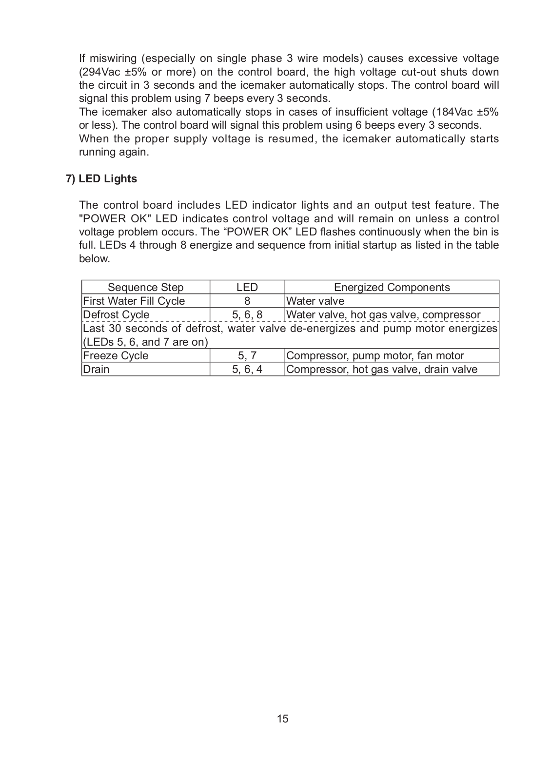
How it Works
Log In / Sign Up
Buy Points
How it Works
FAQ
Contact Us
Questions and Suggestions
Users
Hoshizaki
Loading...
K
KM1100MAJ50
3
KM1100MRJ
5
KM115BAJ
3
KM1301SAJE
4
KM1301SRH
8
KM1301SRJ3
4
KM1301SWH3
10
KM1340MAJ
5
KM1340MRH with URC-14F
KM1340MRJ
5
KM1340MRJ3
5
KM1340MWJ
5
KM1400SWH3M
5
KM1400SWHM
6
KM1601MRJ3
4
KM1601SAH
7
KM1601SAH3
9
KM1601SRH
14
KM1601SRH3
12
KM1601SRH350
KM1601SRJ3
5
KM1601SWH3
13
KM1900SAH
7
KM1900SAH350
3
KM1900SRH3
8
KM1900SWJ3
4
KM2000SWE3
2
KM201BAH
8
KM2100SRH3
9
KM2100SRH350
2
KM2100SWH350
KM2200SRJ3
3
KM231BAJ
2
KM2500SRH3
9
KM2600SRJ3
3
KM2600SWJ3
3
KM260BAH
8
KM301BWJ
KM30A
4
KM320MWH
12
KM350MWJ
4
KM515MAH
14
KM515MRH
14
KM520MAJ
4
KM520MAJE
4
KM520MRJ
4
KM660MAJE
5
KM660MRJ
4
KM-900MRH
5
KM-900MRH3
4
KM-900MWF
3
KM-900MWH
5
KM901MAH
12
KM-901MAH50
2
KM-901MAJ
2
KM-901MRH
7
KM901MRH3
14
KM-901MRH3 with URC-9F
KM-901MRH50
2
KM-901MRH with URC-9F
KM901MRJ
5
KM901MRJ3
5
KM-901MWH
11
KM-901MWJ
2
KMD-201AA
3
KMD-201AWA
2
KMD-270AA
4
KMD-270AWA
3
KMD-410MAH
9
KMD410MWH
8
KMD450MAH
6
KMD-450MWH
5
KMD460MAH
7
KMD-460MAJ
3
KMD-460MWH
4
KMD460MWJ
5
KMD-530MAH
2
KMD-530MAJ
2
KMD-530MRH
5
KMD-530MRJ
2
KMD-530MWH
2
KMD-530MWJ
2
KMD-700MAH
5
KMD-700MRH
5
KMD-700MWH
5
KMD-850MAH
6
KMD850MRH
10
KMD-850MWH
7
KMD-860MAJ
KMD860MRJ
4
KMD-860MWJ
KMD-900MAH
2
KMD-900MRH
3
KMD-900MWH
3
KMD-901MAH
5
KMD901MR
KMD-901MRH
6
KMD901MWH
9
KMH2000SRH
6
KMH2000SRH3
6
Loading...
Loading...
Nothing found
KM30A
SERVICE MANUAL
65 pgs
5.69 Mb
0
User guide
41 pgs
1.76 Mb
0
User Manual
31 pgs
2.16 Mb
0
Instruction Manual
36 pgs
2.37 Mb
0
Table of contents
Loading...
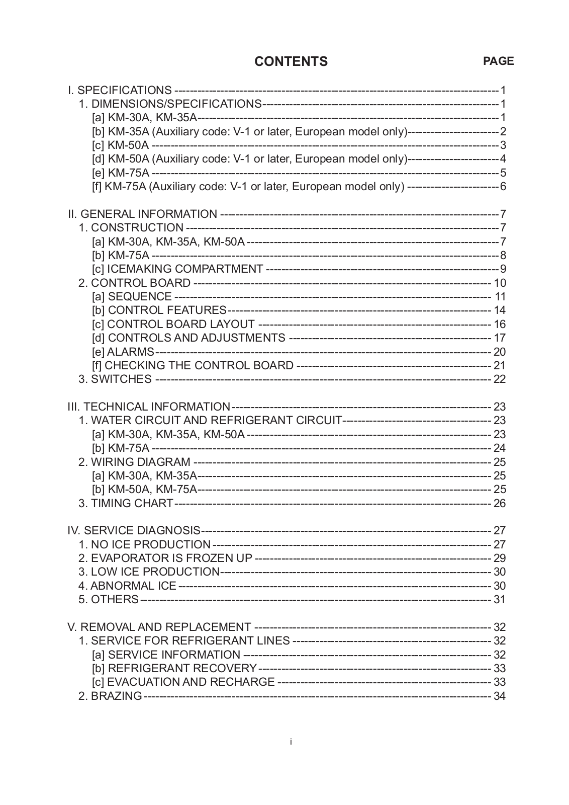
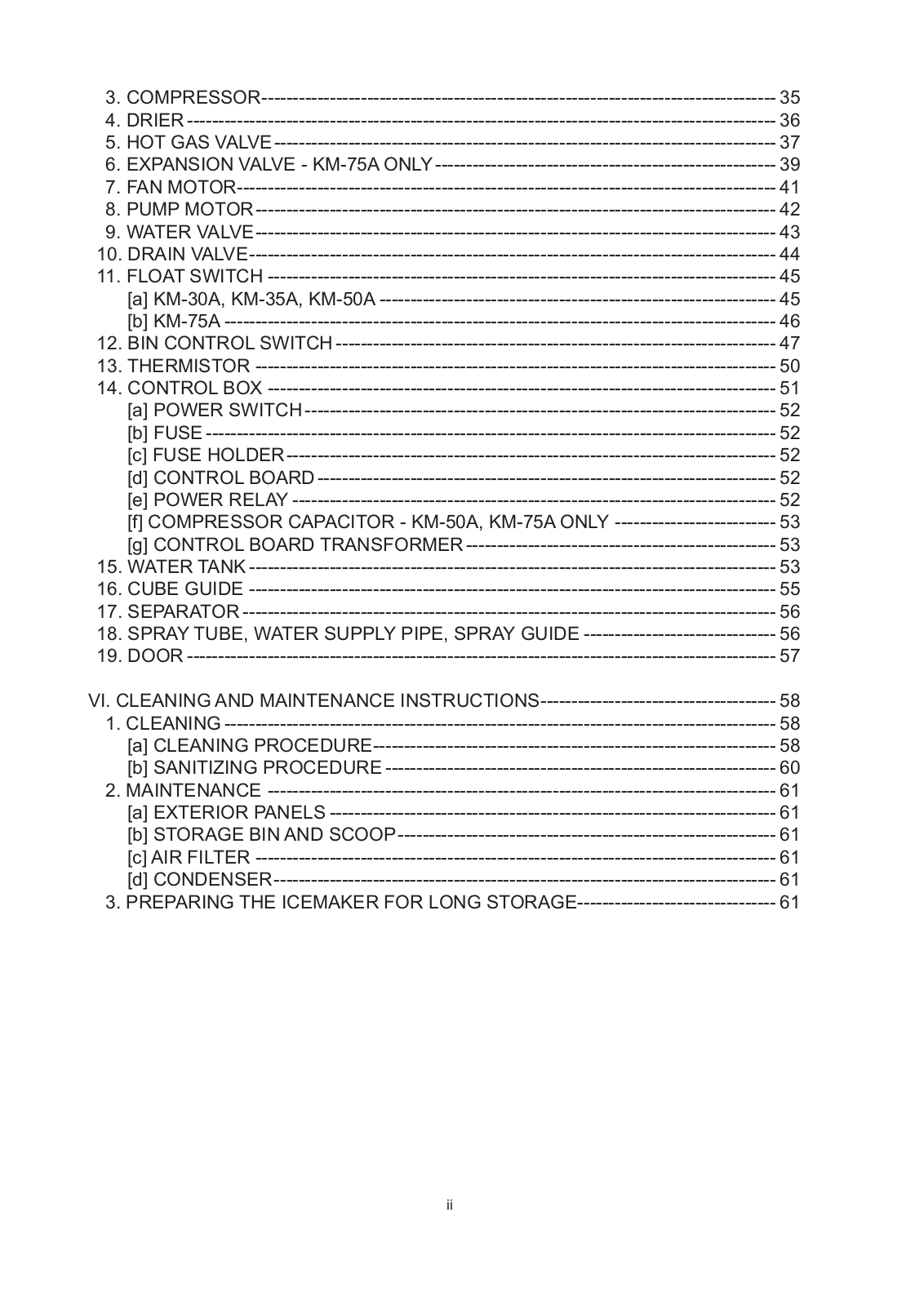
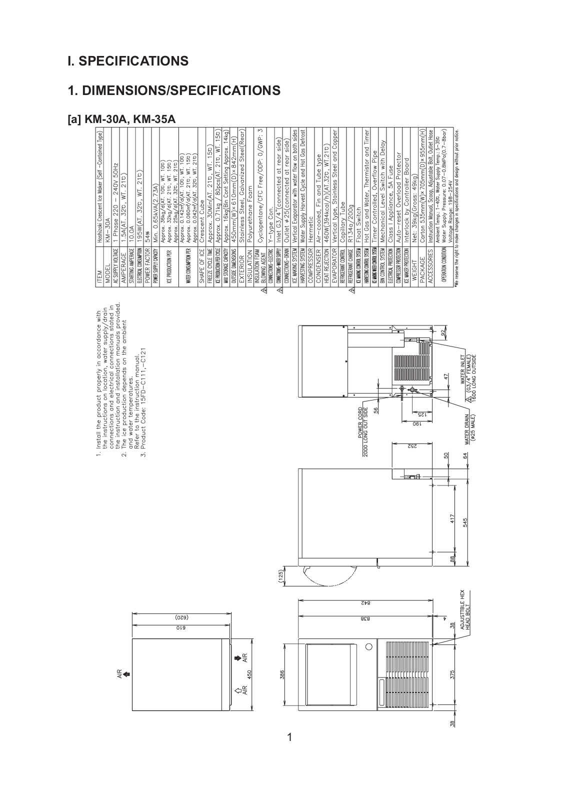
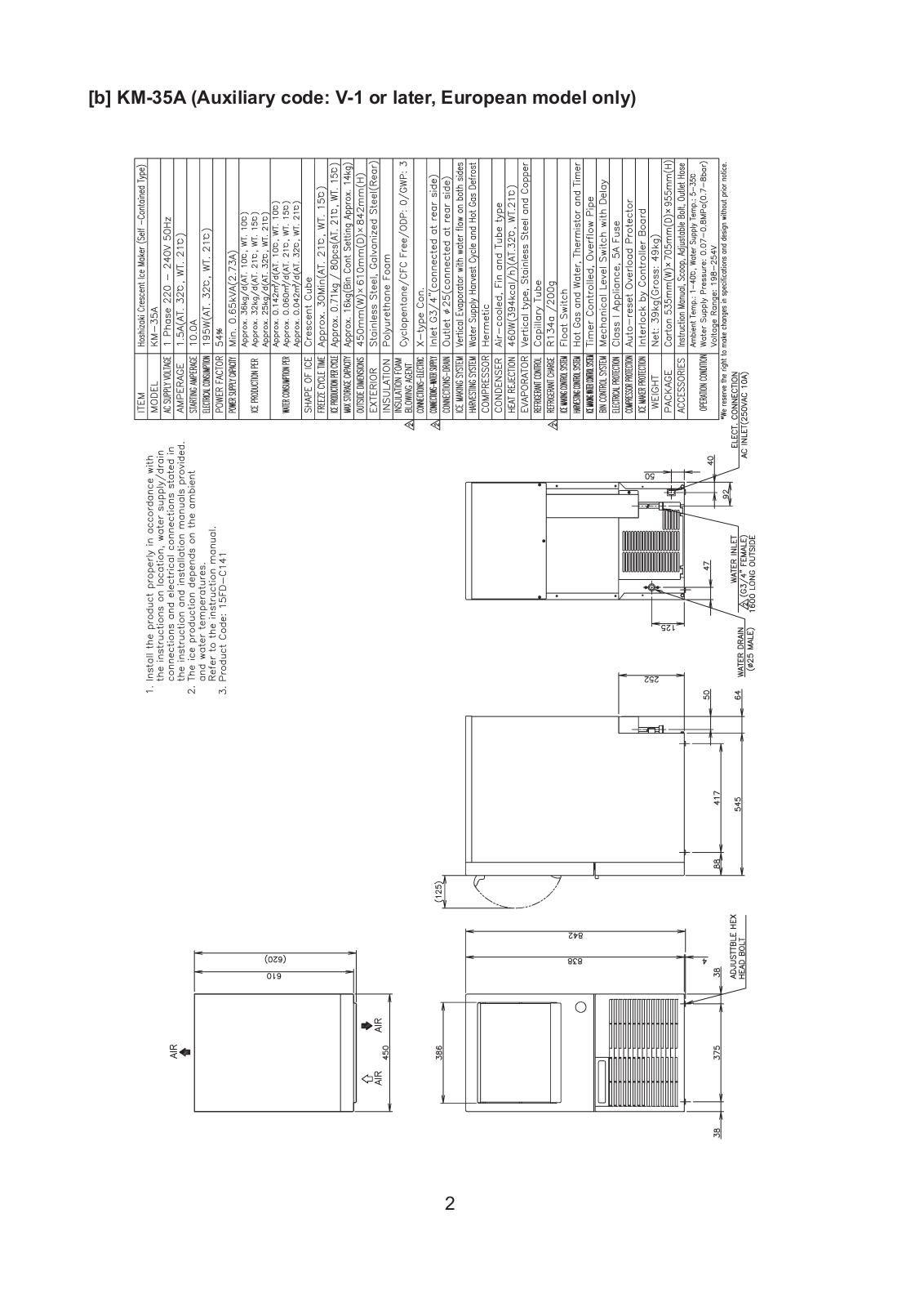
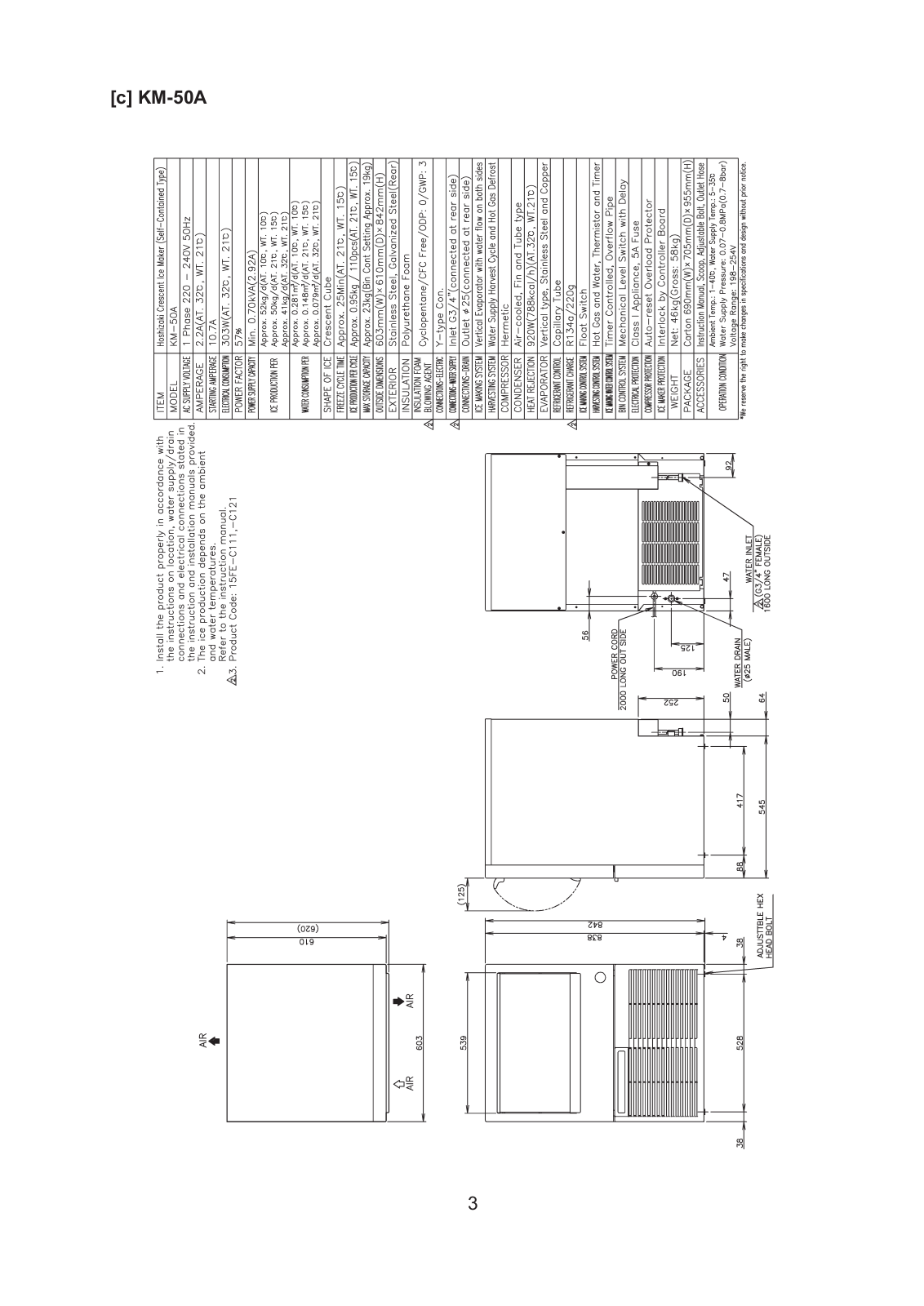
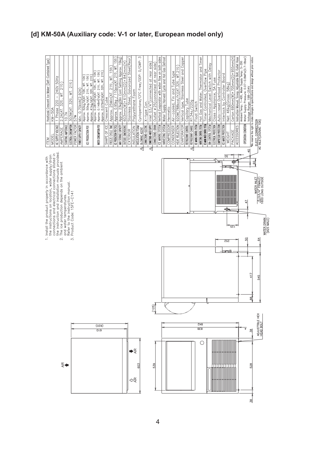
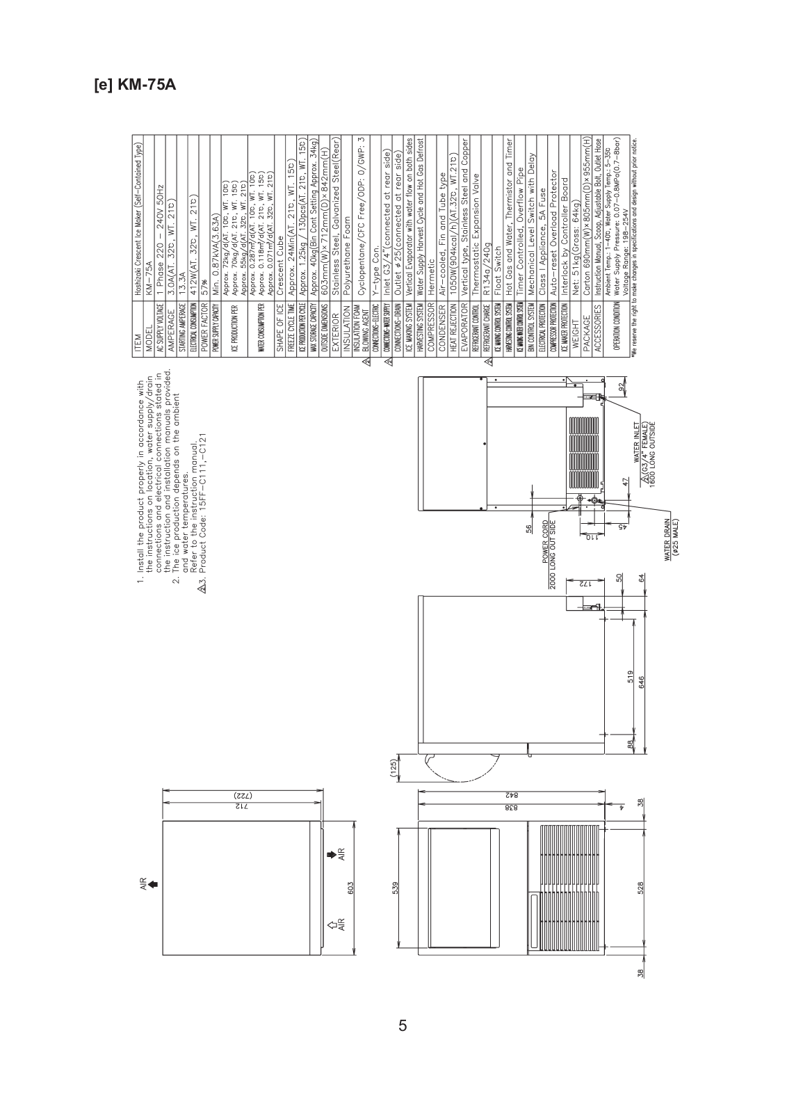
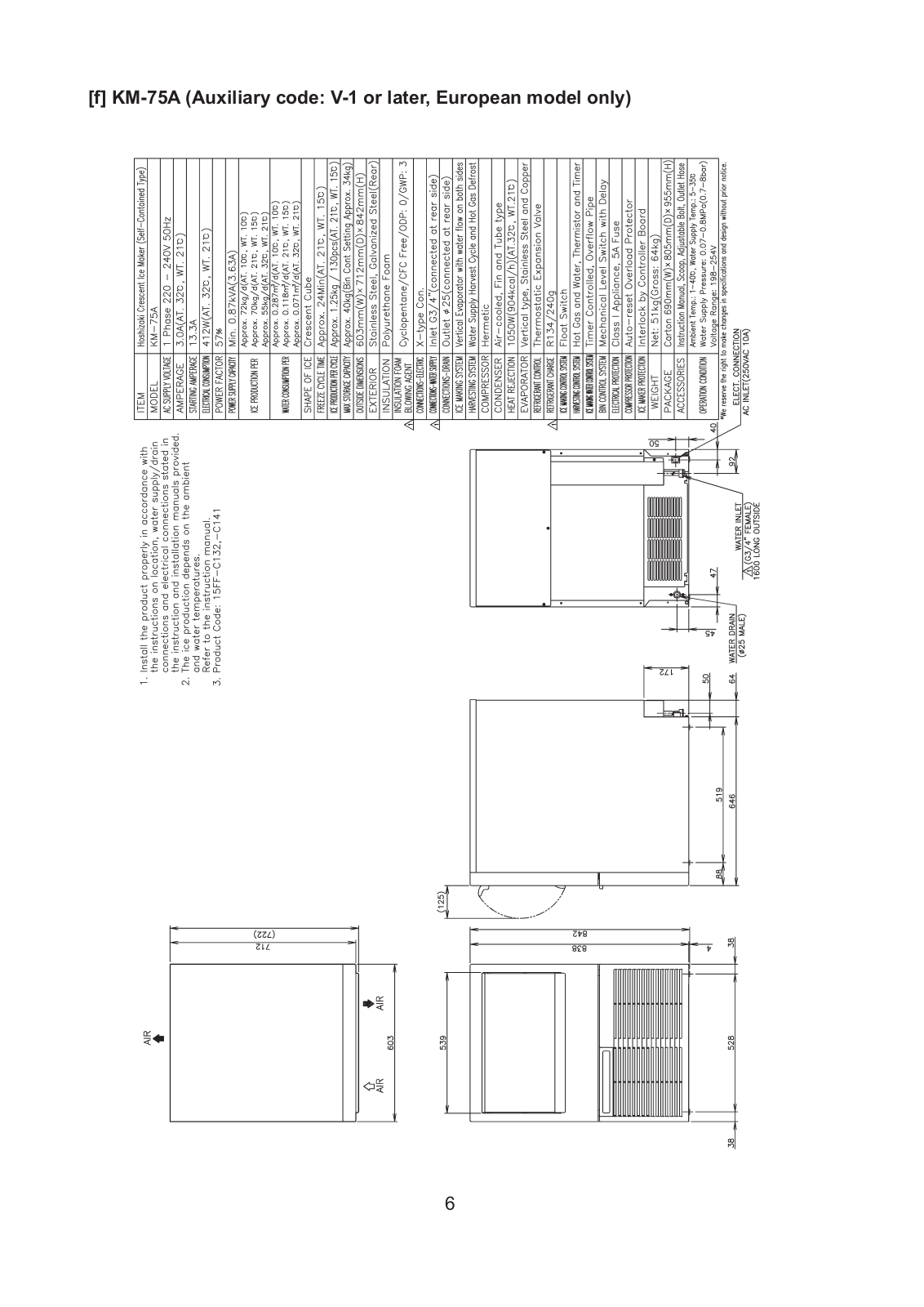
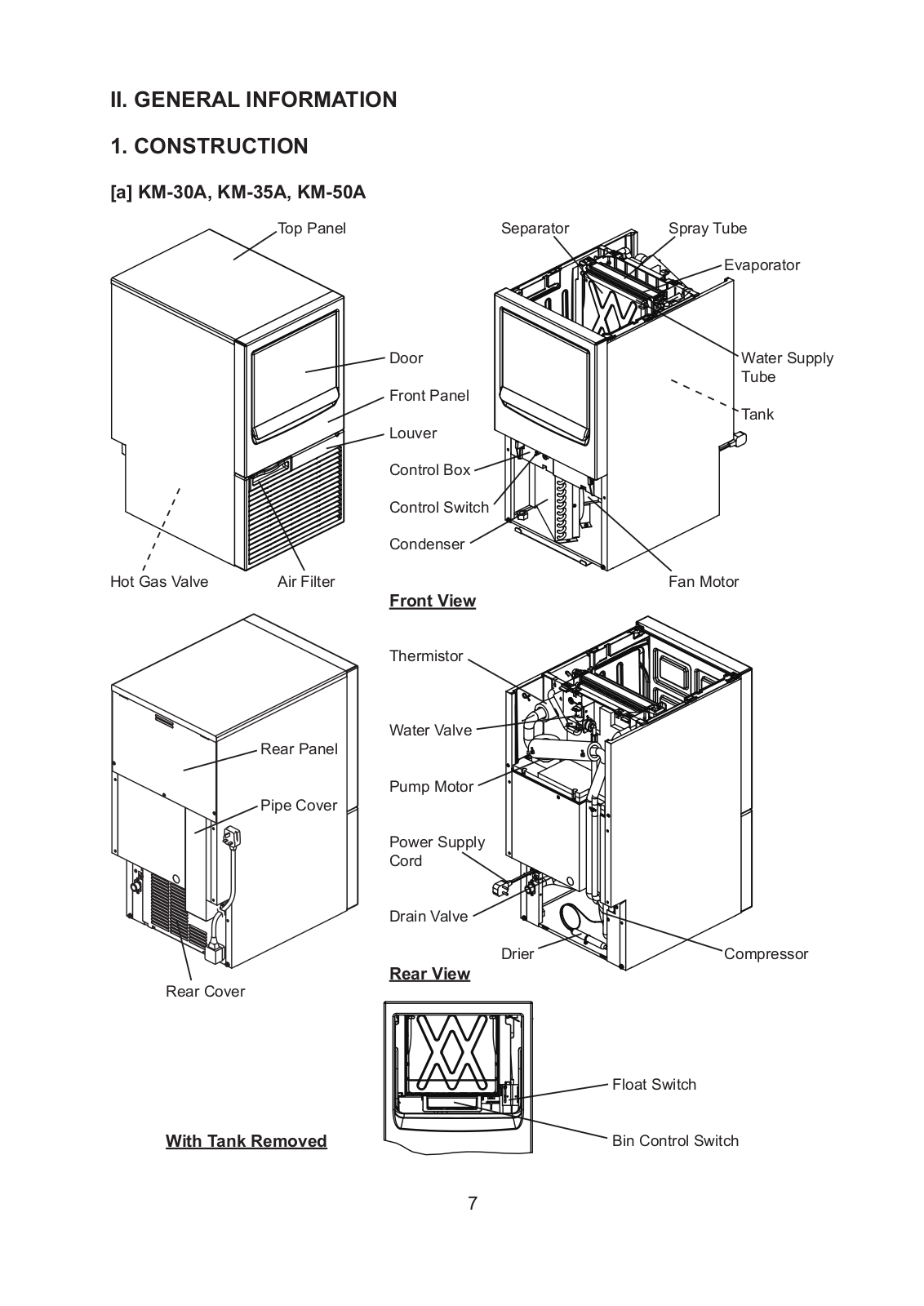
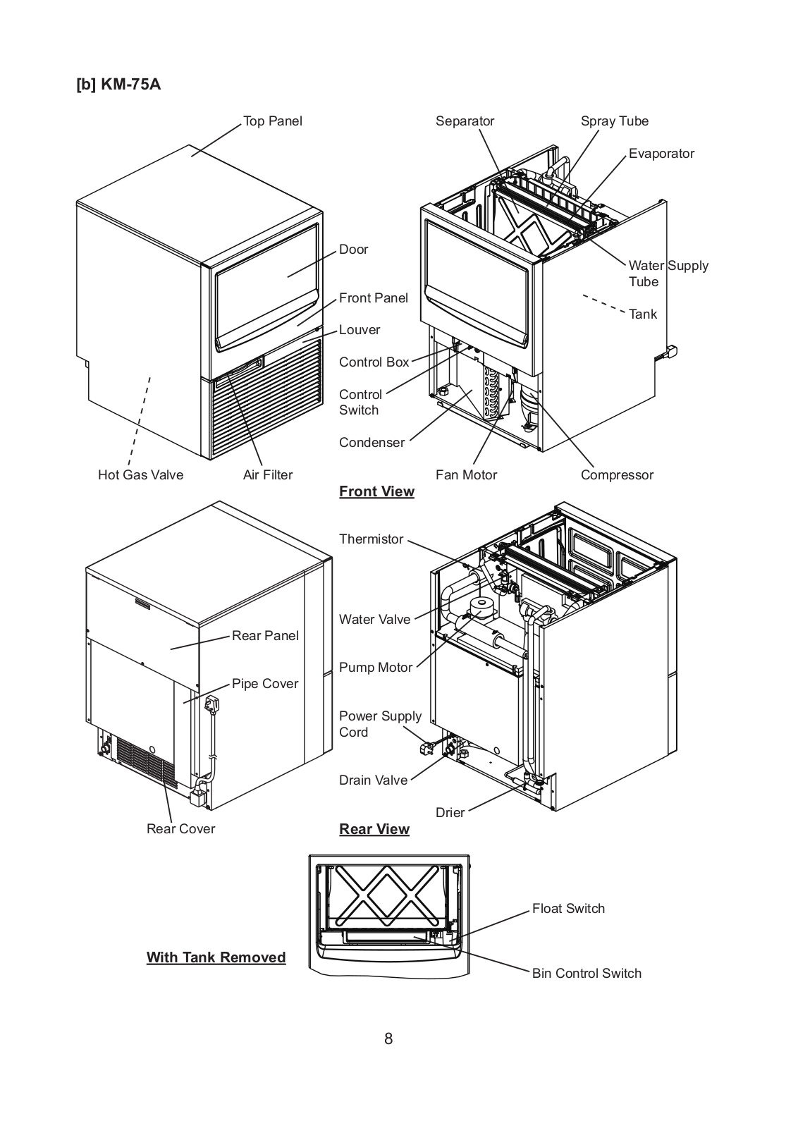
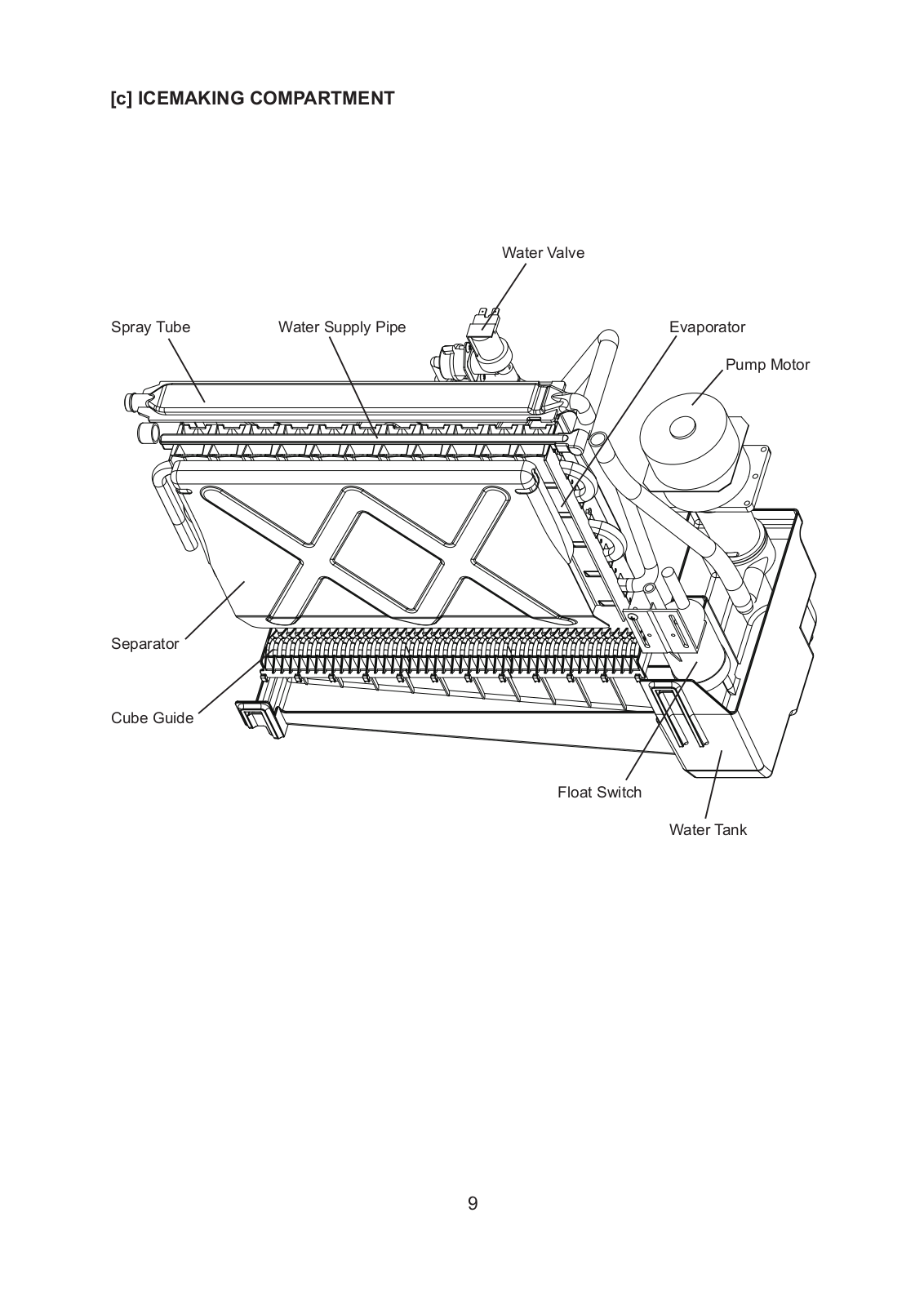
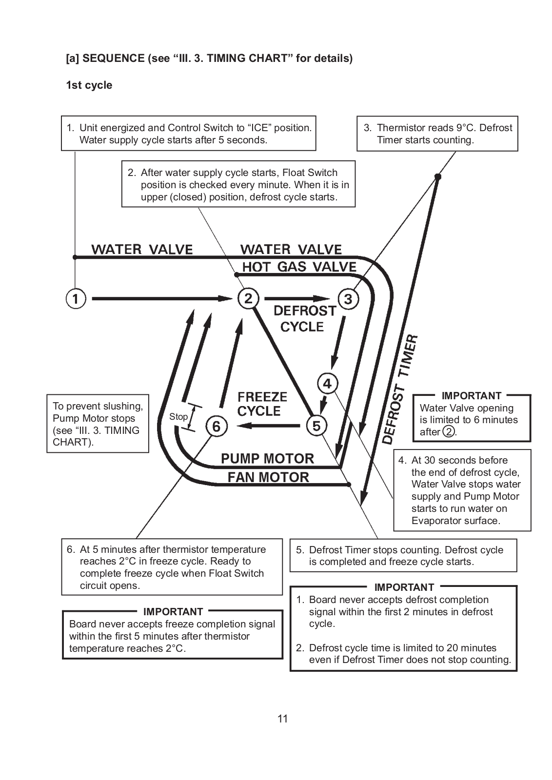
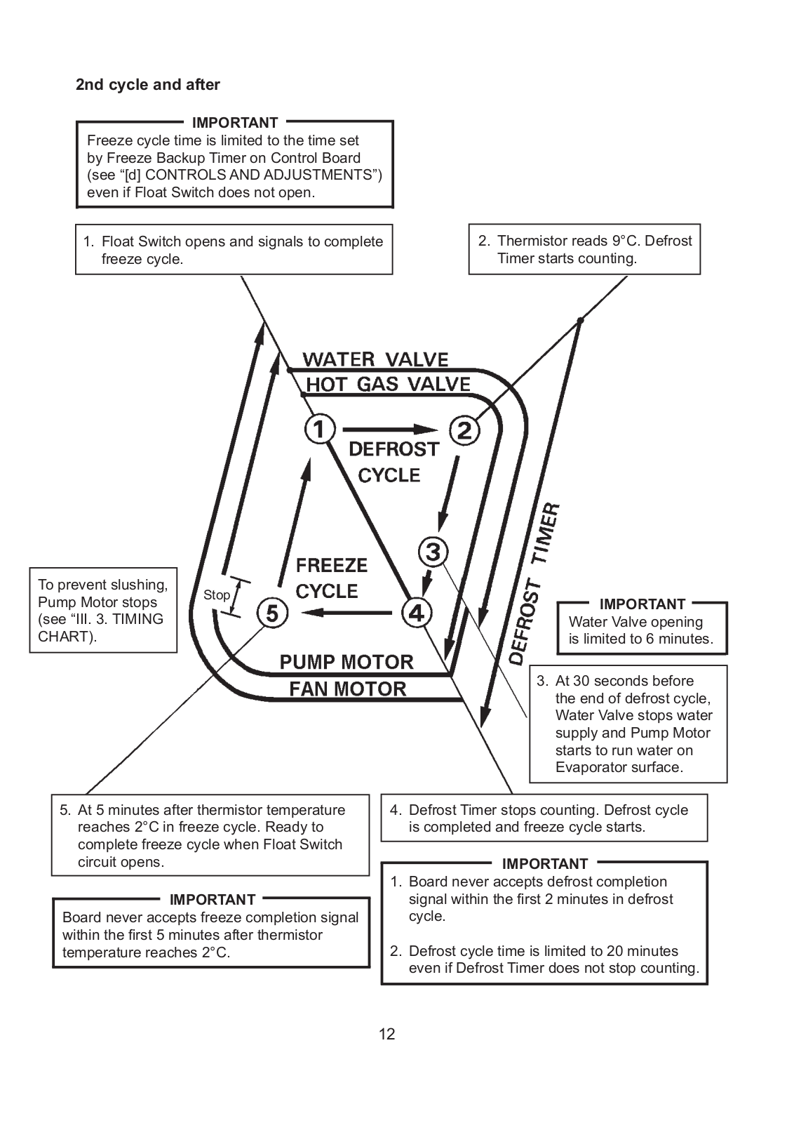
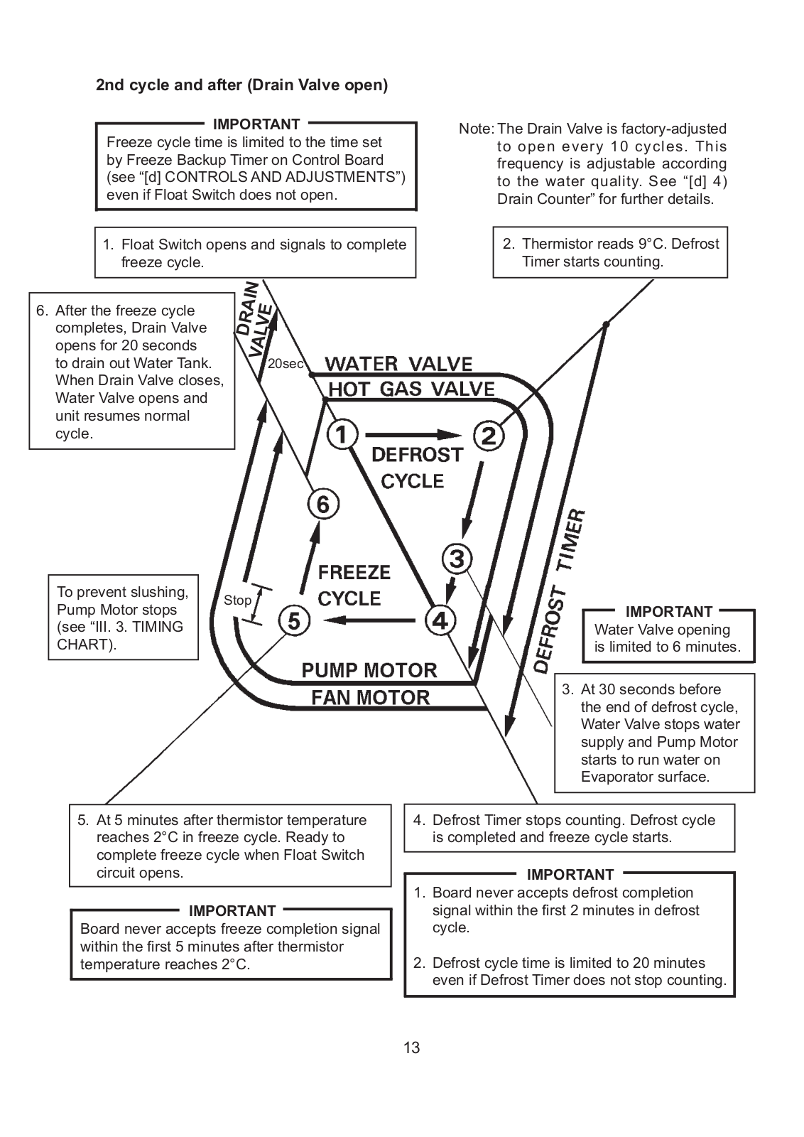
Hoshizaki KM-30A, KM-35A, KM-50A, KM-75A SERVICE MANUAL
...
Hoshizaki SERVICE MANUAL
Download
Specifications and Main Features
Frequently Asked Questions
User Manual
Download
Loading...
+
45
hidden pages
Unhide
You need points to download manuals.
1 point = 1 manual.
You can buy points or you can get point for every manual you upload.
Buy points
Upload your manuals
 Loading...