

Page 1
Parts List
Stackable Crescent Cuber
Models
KM-1900SAJ/3
KM-1900SWJ/3
KM-1900SRJ/3
hoshizakiamerica.com
Number: 71384
Issued: 8-31-2017
Revised: 3-26-2018
Page 2

CONTENTS
Auxiliary Codes ...................................................................................................................... 3
Note About Ordering Parts .................................................................................................... 3
A. Main Assembly & Refrigeration Circuit .............................................................................. 4
KM-1900SAJ/3 .................................................................................................................. 4
KM-1900SWJ/3 ................................................................................................................. 6
KM-1900SRJ/3 .................................................................................................................. 8
B. Water Circuit .................................................................................................................... 10
C. Control Box Assembly ..................................................................................................... 13
D. Accessories & Labels ...................................................................................................... 14
2
Page 3

Auxiliary Codes
KM-1900SAJ
G-0 May 2017
G-1 October 2017
H-0 January 2018
KM-1900SAJ3
G-0 May 2017
G-1 October 2017
H-0 January 2018
KM-1900SWJ
G-0 May 2017
G-1 October 2017
H-0 March 2018
KM-1900SWJ3
G-0 May 2017
G-1 October 2017
KM-1900SRJ
G-0 May 2017
G-1 October 2017
H-0 January 2018
KM-1900SRJ3
G-0 May 2017
G-1 November 2017
H-0 January 2018
Auxiliary Code Breakdown
The auxiliary code is the rst two characters in the serial number. The rst character
indicates the year. Years progress or regress in alphabetical order. The series runs from
"A" through "V" and the letters "I" and "O" are skipped. The second character indicates
signicant part changes within a year. Base is "0" and this number advances for each
change. In cases where there is a letter in parentheses, this designates the month. This is
the last character in the serial number. The series runs from "(A)" through "(M)" and the
letter "(I)" is skipped. This designation is only included when identifying a parts change
within an auxiliary code.
Note About Ordering Parts
Most assemblies cannot be ordered as complete units; parts in the assemblies generally
must be ordered separately.
3
Page 4
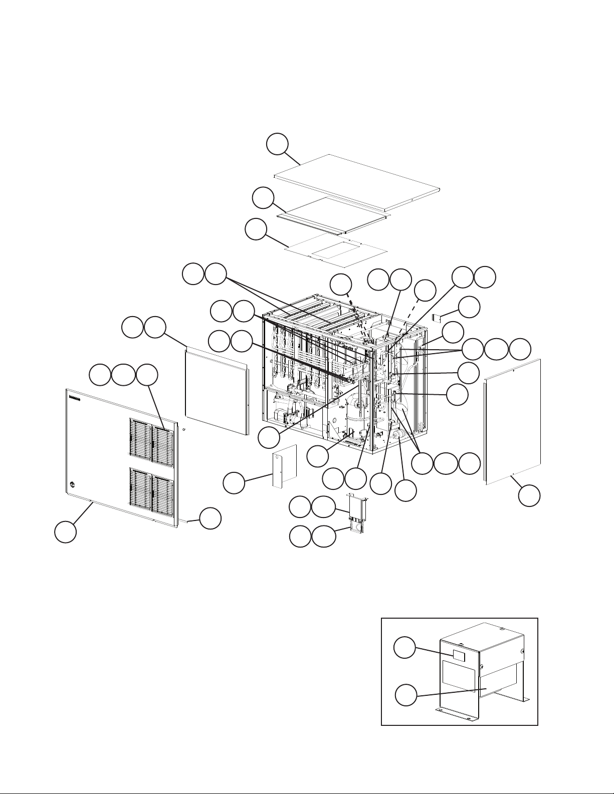
A. Main Assembly & Refrigeration Circuit
KM-1900SAJ/3
G-0 to H-0
3
6
7
10 10a 11
18 19
28
21
22
5a5
23
24
25 27
29
17
3231
9
3433 33a
35
30
20
16
8
13
26 27
13a
35
36
33a
3433
4
2
1
12
12a
Model Shown: KM-1900SAJ
4
15
14
KM-1900SAJ3
Page 5
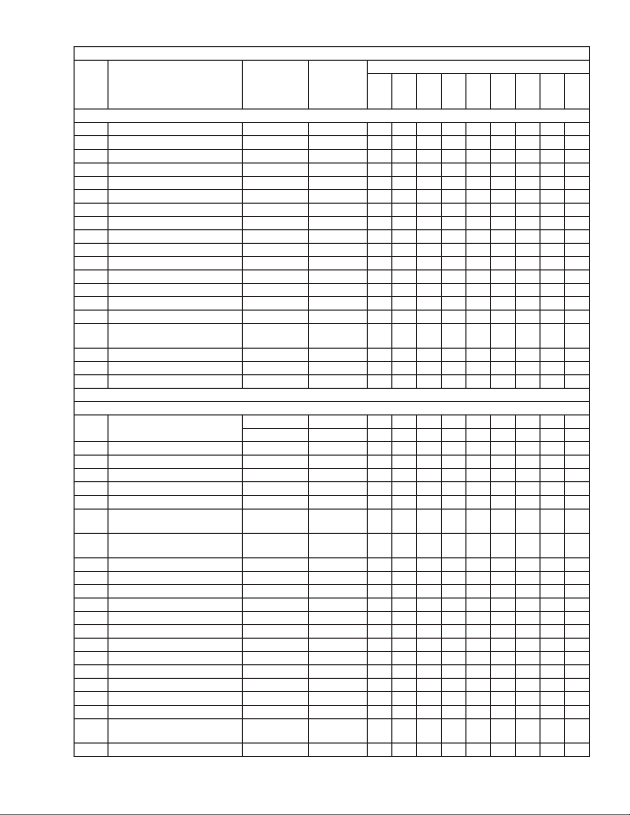
Title: A. Main Assembly & Refrigeration Circuit Model: KM-1900SAJ/3
G-0
Index
No. Description
1 Front Panel 3A1800G01 1
2 Gasket L=1219 mm 4A0808L02 1
3 Top Panel 2A2255-01 1
4 Right Side Panel 215381G02 1
5 Front Insulation 326041G01 1
5a Thumbscrew 415949G10 1
6 Top Insulation 324216G01 1
7 Spacer 324321-01 1
8 Control Box Cover 3A2386-01 1
9 Junction Box Cover 433410-01 1
10 Louver 1A0548-01 4
10a Push Retainer 4A2414-01 12
11 Air Filter 2A2063G01 4
12 Mechanical Bin Control 2A4393G01 1
12a Thumbscrew 415949G10 2
13 Mechanical Bin Control
Mounting Bracket
13a Thumbscrew 415949G10 2
14 Main Transformer KM-1900SAJ3 4A5695-01 1
15 Voltage Tap Switch KM-1900SAJ3 4A1477-01 1
Material or
Model Number Part Number
Main Assembly
3A5726-01 1
to
H-0
Required Number
Refrigeration Circuit
16 Compressor KM-1900SAJ 4A4581-01 1
KM-1900SAJ3 4A4582-01 1
17 Condenser 2A1991-01 1
18 Evaporator Bank (Right or Left) SP-5261 2
19 Separator Hook 324152-01 8
20 Heat Exchanger 1A4462G01 1
21 Thermostatic Expansion Valve 4A1414-01 3
22 Thermostatic Expansion Valve
Cover
23 Thermostatic Expansion Valve
Bulb Holder
24 Clamp 443461-02 3
25 Hot Gas Valve Body 4A3978-01 1
26 Liquid Line Valve Body 4A3276-01 1
27 Valve Coil 4A3277-01 2
28 Check Valve 4A1373-01 3
29 Strainer 441569-02 1
30 High-Pressure Switch 463180-04 1
31 Thermistor 429006-03 1
32 Thermistor Holder 438247-01 1
33 Fan Motor 4A3158-01 2
33a Self-Locking Nut 7N21I0832 8
34 Fan Blade 4A0197-01 2
35 Fan Motor Capacitor 5.0MFD,
250VAC
36 Drier 4A1338-01 1
3A0944-01 3
3A0107-01 3
443192-02 2
5
Page 6

A. Main Assembly & Refrigeration Circuit
KM-1900SWJ/3
G-0 to H-0
3
6
7
29
20
9
3231
18 19
5a
5
2221
25 27
28
2423
16
17
30
15
8
14
33
26 27
11
11a
4
2
1
10 10a
Model Shown: KM-1900SWJ
12
13
6
KM-1900SWJ3
Page 7

Title: A. Main Assembly & Refrigeration Circuit Model: KM-1900SWJ/3
G-0
Index
No. Description
1 Front Panel 3A1838G01 1
2 Gasket L=1219 mm 4A0808L02 1
3 Top Panel 2A2255-01 1
4 Right Side Panel 215381G02 1
5 Front Insulation 326041G01 1
5a Thumbscrew 415949G10 1
6 Top Insulation 324216G01 1
7 Spacer 324321-01 1
8 Control Box Cover 3A2386-01 1
9 Junction Box Cover 433410-01 1
10 Mechanical Bin Control 2A4393G01 1
10a Thumbscrew 415949G10 2
11 Mechanical Bin Control
Mounting Bracket
11a Thumbscrew 415949G10 1
12 Main Transformer KM-1900SWJ3 4A5695-01 1
13 Voltage Tap Switch KM-1900SWJ3 4A1477-01 1
Material or
Model Number Part Number
Main Assembly
3A5726-01 1
to
H-0
Required Number
Refrigeration Circuit
14 Compressor KM-1900SWJ 4A4581-01 1
KM-1900SWJ3 4A4582-01 1
15 Water-Cooled Condenser 3A7324-01 1
16 Water Regulating Valve 4A0911-07 1
17 Male Connector 4A1087-01 1
18 Evaporator Bank (Right or Left) SP-5261 2
19 Separator Hook 324152-01 8
20 Heat Exchanger 1A4467G01 1
21 Thermostatic Expansion Valve 4A1414-01 3
22 Thermostatic Expansion Valve
Cover
23 Thermostatic Expansion Valve
Bulb Holder
24 Clamp 443461-02 1
25 Hot Gas Valve Body 4A3978-01 1
26 Liquid Line Valve Body 4A3276-01 1
27 Valve Coil 4A3277-01 2
28 Check Valve 4A1373-01 3
29 Strainer 441569-02 1
30 High-Pressure Switch 463180-05 1
31 Thermistor L=1050 mm 429006-03 1
32 Thermistor Holder 438247-01 1
33 Drier 4A1338-01 1
3A0944-01 3
3A0107-01 3
7
Page 8

A. Main Assembly & Refrigeration Circuit
KM-1900SRJ/3
G-0 to H-0
3
34
6
35
7
Rear View
18 19
28
25 27
29
10
2221
5a
5
23
24
9
3231
30
17
20
8
15
16
26 27
33
4
2
12 12a
1
11 11a
Model Shown: KM-1900SRJ
13
14
KM-1900SRJ3
8
Page 9

Title: A. Main Assembly & Refrigeration Circuit Model: KM-1900SRJ/3
G-0
Index
No. Description
1 Front Panel 3A1838G01 1
2 Gasket L=1219 mm 4A0808L02 1
3 Top Panel 2A8390-01 1
4 Right Side Panel 2A8391-01 1
5 Front Insulation 326041G01 1
5a Thumbscrew 415949G10 1
6 Top Insulation 324216G01 1
7 Spacer 324321-01 1
8 Control Box Cover 3A2386-01 1
9 Junction Box Cover A 433410-01 1
10 Junction Box Cover B 4A4704-01 1
11 Mechanical Bin Control 2A4393G01 1
11a Thumbscrew 415949G10 2
12 Mechanical Bin Control
Mounting Bracket
12a Thumbscrew 415949G10 1
13 Main Transformer KM-1900SRJ3 4A5695-01 1
14 Voltage Tap Switch KM-1900SRJ3 4A1477-01 1
Material or
Model Number Part Number
Main Assembly
3A5726-01 1
to
H-0
Required Number
Refrigeration Circuit
15 Compressor KM-1900SRJ 4A4581-01 1
KM-1900SRJ3 4A4582-01 1
16 Crankcase Heater 4A5397-02 1
17 Receiver 440366-01 1
18 Evaporator Bank (Right or Left) SP-5261 2
19 Separator Hook 324152-01 8
20 Heat Exchanger 1A4462G01 1
21 Thermostatic Expansion Valve 4A1414-01 3
22 Thermostatic Expansion Valve
Cover
23 Thermostatic Expansion Valve
Bulb Holder
24 Clamp 443461-02 3
25 Hot Gas Valve Body 4A3978-01 1
26 Liquid Line Valve Body 4A3276-01 1
27 Valve Coil 4A3277-01 2
28 Check Valve 4A1373-01 3
29 Strainer 441569-02 1
30 High-Pressure Switch 463180-04 1
31 Thermistor L=1050 mm 429006-03 1
32 Thermistor Holder 438247-01 1
33 Drier 4A1338-01 1
34 Liquid Line Coupling 426554-01 1
35 Discharge Line Coupling 434072-01 1
3A0944-01 3
3A0107-01 3
9
Page 10

B. Water Circuit
KM-1900S_J/3
G-0 to H-0
21
34
13
15
24
26
16
46
14
25
37
38
49
45
17
18
19
10
11
12
48
40
41
47
27
28
29
33
23
39
3a
3c
42
3
3b
49
5
8
4b
7
4
6
20
44
1
22
31
10
32
30
43
36
3e
21
40
35
Pump Motor Assembly
2
9
4a
3d
Page 11

Title: B. Water Circuit Model: KM-1900S_J/3
Index
No. Description
1 Pump Motor Assembly
(includes items 2 through 9b)
2 Pump Motor 2U0106-01 1
3 Pump Flange 215662-01 1
3a Tooth Washer 7R22-0600 2
3b Hex Head Bolt 6×40 7B02-0640 4
3c Flat Washer 7W22-0600 4
3d Split Lock Washer 7L22-0600 4
3e Hex Nut 7N12-0600 4
4 Pump Housing 213687-01 1
4a Hex Head Bolt 4×55 7B02-0455 4
4b Hex Flange Nut 7J02-0400 4
5 Mechanical Seal 4A3820-01 1
6 Packing 428547-01 1
7 Impeller 436584-01 1
8 Pin 4A0648-01 1
9 Pump Motor Bracket 323904-01 1
10 Water Supply Pipe KM-1900SAJ/3
11 Rubber Gasket 413854-03 1
12 Inlet Water Valve 3 U0111- 01 1
13 Distributor Hose A 325738-01 1
14 Distributor Hose B 325738-02 1
15 Distributor Hose C 325739-01 2
16 Joint Pipe 439297-01 1
17 Spray Tube 437049G01 6
18 Spray Guide 2A4282-02 6
19 Separator A 215046-01 2
20 Vinyl Hose L=230 mm 7716-2732 1
21 Cube Guide 214243-01 2
22 Hose A 435091-01 1
23 Hose B 325867-01 1
24 Distributor A 439266-01 1
25 Distributor B (Tee) 439239-01 1
26 Distributor C 439238-01 1
27 Drain Valve Housing 323613-01 1
28 Spring 322110-01 1
29 Valve Seat 433705-01 1
30 Overow Cap 325866-01 1
31 Float Switch Connector 426799-04 1
32 Float Switch 4A3624-01 1
33 O-Ring 7611-G035 1
34 Drain Hose 325869-01 1
35 Drain Plug 309246-01 1
36 O-Ring 7611-P015 1
Material or
Model Number Part Number
S-0730 215692A03 1
4A0768G04 1
KM-1900SWJ/3
KM-1900SRJ/3 4A0768G11 1
Required Number
G-0
to
H-0
11
Page 12

Title: B. Water Circuit Model: KM-1900S_J/3
Index
No. Description
37 Joint Hose 439309-01 1
38 Bypass Hose 439237-02 1
39 Control Valve Ball Valve S-0761 439293-01 1
40 Control Valve Male Adaptor 325826-01 2
41 Control Valve Microswitch 4A2546-01 1
42 Control Valve Handle 215383-01 1
43 Silicone Hose L=190 mm 7730I3812 1
44 Silicone Hose L=430 mm 7730I3896 1
45 Vinyl Hose L=40 mm 7716-1519 1
46 Vinyl Hose L=550 mm 7716-2732 1
47 Splash Guard 4A6141-01 2
48 Splash Curtain 1A4890-01 2
49 Separator 3A9811-01 24
Hose Clamp 25 mm 427443-03 9
Hose Clamp 13.5 mm 427443-07 6
Hose Clamp 32 mm 427443-09 6
Hose Clamp 17-21 mm 4A2017-05 1
Material or
Model Number Part Number
Hose Clamps
Required Number
G-0
to
H-0
12
Page 13

C. Control Box Assembly
KM-1900S_J/3
G-0 to H-0
4
12
1
3
4a
6 7
4a
4
1
3
6 7
8
X10 X 11 X12
10
Title: C. Control Box Assembly Model: KM-1900S_J/3
Index
No. Description
1 Compressor Relay KM-1900SAJ
2 Pump Motor Capacitor 15MFD,
3 Control Transformer 3A0172-01 1
4 Control Board 2A7664-02 1
4a Control Board Support 4A0336-03 4
5 Toggle Switch (control) 443119-01 1
6 Fuse Holder 4A5443-01 1
7 Fuse AGC-10A,
8 Wire Harness 4A5197G01 1
9 Relay
10 Start Capacitor 189-227MFD,
11 Run Capacitor 35MFD,
12 Start Relay 4A1107-09 1
11
KM-1900SRJ
Magnetic Contactor KM-1900SAJ3
X10 = Pump Direction Relay
X11 = X10 Control Relay
X12 = Anti-Slush Control Relay
X13 = Crankcase Heater KM-1900SRJ 1
2
X13
9
5
Material or
Model Number Part Number
4A3140-01 1
KM-1900SWJ
KM-1900SRJ
4A0794-02 1
KM-1900SWJ3
KM-1900SRJ3 4A0794-01 1
439705-01 1
240VAC
4A0893-07 1
250VAC
All Models 406132-07 3
3A0076-12 1
330VAC
3A2005-12 1
440VAC
G-0
to
H-0
X10 X 11 X12
2
KM-1900SRJ3
Required Number
9
5
13
Page 14

D. Accessories & Labels
KM-1900S_J/3
G-0 to H-0
1
2
Title: D. Accessories & Labels Model: KM-1900S_J/3
Index
No. Description
1 Hoshizaki Emblem Label 4A0560-01 1
2 Penguin Label 475552L02 1
3 Universal Brace 4A0363-01 2
3a Hex Bolt 5×12, SS 7B02-0512 4
Material or
Model Number Part Number
Required Number
G-0
to
H-0
14
 Loading...