

Hoshizaki HR24A User Manual

Hoshizaki
Hoshizaki America, Inc.
Undercounter Refrigerator
Model
HR24A
“A Superior Degree
of Reliability”
www.hoshizaki.com
SERVICE MANUAL
Number: 73187
Issued: 12-7-2011

WARNING
Only qualied service technicians should install and service the appliance. To
obtain the name and phone number of your local Hoshizaki Certied Service
Representative, visit www.hoshizaki.com. No service should be undertaken until
the technician has thoroughly read this Service Manual. Failure to service and
maintain the appliance in accordance with this manual will adversely affect safety,
performance, component life, and warranty coverage. Proper installation is the
responsibility of the installer. Product failure or property damage due to improper
installation is not covered under warranty.
Hoshizaki provides this manual primarily to assist qualied service technicians in the
service of this appliance.
Should the reader have any questions or concerns which have not been satisfactorily
addressed, please call, send an e-mail message, or write to the Hoshizaki Technical
Support Department for assistance.
Phone: 1-800-233-1940; (770) 487-2331
Fax: 1-800-843-1056; (770) 487-3360
E-mail: techsupport@hoshizaki.com
HOSHIZAKI AMERICA, INC.
618 Highway 74 South
Peachtree City, GA 30269
Attn: Hoshizaki Technical Support Department
Web Site: www.hoshizaki.com
NOTE: To expedite assistance, all correspondence/communication MUST include the
following information:
• Model Number
• Serial Number
• Complete and detailed explanation of the problem.
2

IMPORTANT
This manual should be read carefully before the appliance is serviced. Read
the warnings and guidelines contained in this booklet carefully as they provide
essential information for the continued safe use, service, and maintenance of the
appliance. Retain this booklet for any further reference that may be necessary.
CONTENTS
Important Safety Information ................................................................................................. 5
I. Specications ...................................................................................................................... 7
A. Electrical and Refrigerant Data ..................................................................................... 7
B. Storage Capacity and Dimensions ................................................................................ 7
1. Storage Capacity ...................................................................................................... 7
2. Dimensions .............................................................................................................. 8
II. General Information ........................................................................................................... 9
A. Construction .................................................................................................................. 9
B. Sequence of Operation ............................................................................................... 10
1. Sequence Cycles and Shutdown ........................................................................... 10
2. Sequence Flow Chart ............................................................................................ 12
C. Control Board and Display Module.............................................................................. 13
1. Control Board Layout ............................................................................................. 14
2. Display Module Layout .......................................................................................... 14
D. Cabinet Temperature ................................................................................................... 15
E. Display Module Icons .................................................................................................. 16
F. Control Panel Lockout .................................................................................................. 16
G. Alarm Safeties ............................................................................................................. 17
H. Service Menu .............................................................................................................. 18
III. Technical Data ................................................................................................................ 24
A. Refrigeration Circuit .................................................................................................... 24
B. Wiring Diagram ............................................................................................................ 25
IV. Service Diagnosis ........................................................................................................... 26
A. Diagnostic Procedure .................................................................................................. 26
B. Control Board Check ................................................................................................... 29
C. Thermistor Check ........................................................................................................ 30
D. Diagnostic Chart ......................................................................................................... 31
V. Replacement of Components .......................................................................................... 33
A. Service for Refrigerant Lines ....................................................................................... 33
1. Refrigerant Recovery ............................................................................................. 33
2. Brazing .................................................................................................................. 34
3. Evacuation and Recharge (R-134a) ...................................................................... 34
B. Important Notes for Component Replacement ............................................................ 35
C. Door Reversal ............................................................................................................. 36
3

VI. Cleaning and Maintenance Instructions ......................................................................... 37
A. Cleaning ...................................................................................................................... 37
1. Exterior ................................................................................................................... 37
2. Cabinet Interior ...................................................................................................... 37
3. Door Gasket .......................................................................................................... 37
4. Shelves .................................................................................................................. 37
B. Maintenance ................................................................................................................ 37
VII. Preparing the Appliance for Periods of Non-Use ........................................................... 38
VIII. Disposal ........................................................................................................................ 39
4
Important Safety Information
Throughout this manual, notices appear to bring your attention to situations which could
result in death, serious injury, damage to the appliance, or damage to property.
WARNING Indicates a hazardous situation which could result in death or
serious injury.
NOTICE Indicates a situation which could result in damage to the
appliance or property.
IMPORTANT Indicates important information about the use and care of the
appliance.
WARNING
This appliance should be destined only to the use for which it has been expressly
conceived. Any other use should be considered improper and therefore dangerous.
The manufacturer cannot be held responsible for injury or damage resulting from
improper, incorrect, and unreasonable use. Failure to service and maintain the
appliance in accordance with this manual will adversely affect safety, performance,
component life, and warranty coverage.
To reduce the risk of death, electric shock, serious injury, or re, follow basic
precautions including the following:
• Only qualied service technicians should install and service this appliance.
• This appliance must be installed in accordance with applicable national, state, and
local codes and regulations.
• This appliance requires an independent power supply of proper capacity. See
the nameplate for electrical specications. Failure to use an independent power
supply of proper capacity can result in a tripped breaker, blown fuse, damage to
existing wiring, or component failure. This could lead to heat generation or re.
• THIS APPLIANCE MUST BE GROUNDED. This appliance is equipped with a
NEMA 5-15 three-prong grounding plug to reduce the risk of potential shock
hazards. It must be plugged into a properly grounded, independent 3-prong wall
outlet. If the outlet is a 2-prong outlet, it is your personal responsibility to have a
qualied electrician replace it with a properly grounded, independent 3-prong wall
outlet. Do not remove the ground prong from the power cord and do not use an
adapter plug.
• Do not use an extension cord.
• To reduce the risk of electric shock, turn off the appliance before unplugging.
• To reduce the risk of electric shock, do not touch the plug with damp hands.
• Do not use an appliance with a damaged power cord. The power cord should not
be altered, jerked, bundled, weighed down, pinched, or tangled. Such actions
could result in electric shock or re. To unplug the appliance, be sure to pull the
plug, not the cord, and do not jerk the cord.
• Do not make any alterations to the appliance. Alterations could result in electric
shock, injury, re, or damage to the appliance.
5

WARNING, continued
• This appliance is not intended for use by persons (including children) with reduced
physical, sensory, or mental capabilities, or lack of experience and knowledge,
unless they have been given supervision or instruction concerning use of the
appliance by a person responsible for their safety.
• Children should be properly supervised around this appliance.
• Do not climb, stand, or hang on the appliance or door or allow children or animals
to do so. Do not climb into the appliance or allow children or animals to do so.
Death or serious injury could occur or the appliance could be damaged.
• Be careful not to pinch ngers when opening and closing the door. Be careful
when opening and closing the door when children are in the area.
• Do not use combustible spray or place volatile or ammable substances near the
appliance. They might catch re.
• Keep the area around the appliance clean. Dirt, dust, or insects in the appliance
could cause harm to individuals or damage to the appliance.
NOTICE
• Protect the oor when moving the appliance to prevent damage to the oor.
• Keep ventilation openings, in the appliance enclosure or in the built-in structure,
clear of obstruction. Do not place anything on top of the appliance. Blockage of
airow could negatively affect performance and damage the equipment.
• Do not tightly pack the cabinet. Allow some space between items to ensure good
air ow. Also allow space between items and interior surfaces.
• Do not store items near the air outlet. They might freeze up and crack or break.
• To prevent deformation or cracks, do not spray insecticide onto the plastic parts or
let them come into contact with oil.
• To avoid damage to the gasket, use only the door handle when opening and
closing.
6
I. Specications
A. Electrical and Refrigerant Data
See the nameplate for electrical and refrigerant data. The nameplate is located inside
the cabinet.
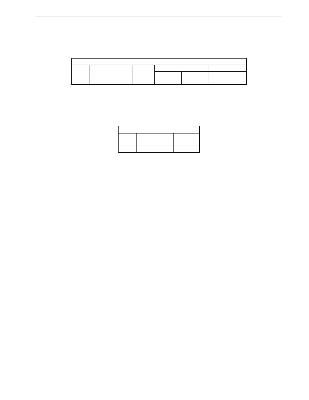
Electrical and Refrigerant Data
Design Pressure (PSIG) Refrigerant (oz.)
Model AC Supply Voltage Amperes
HR24A 115/60/1 4 360 120 2.80
HIGH LOW 134a
We reserve the right to make changes in specications and design without prior notice.
B. Storage Capacity and Dimensions
1. Storage Capacity
Storage Capacity
Interior Storage
Model
HR24A 3.67 2.26
Capacity (ft
We reserve the right to make changes in specications and design without prior notice.
3
)
Total Shelf
Space (ft
2
)
7
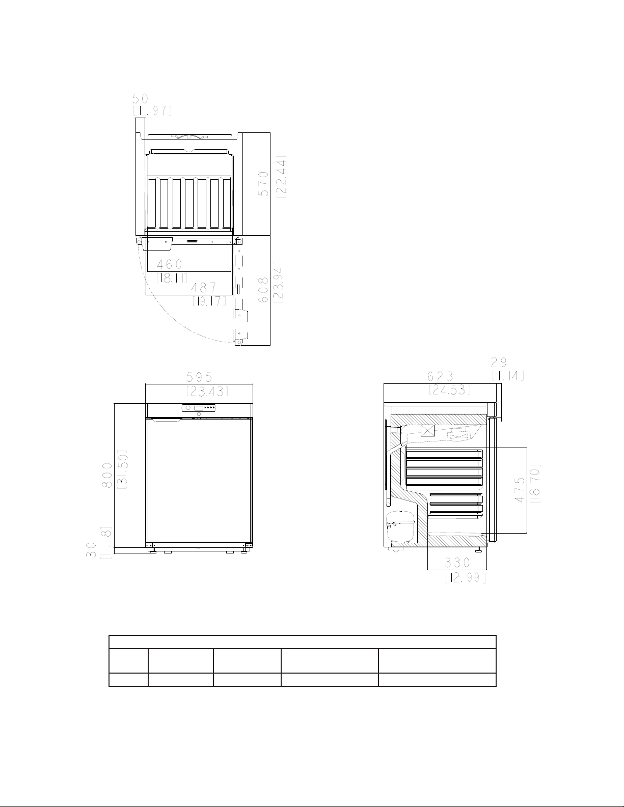
2. Dimensions
Unit: mm [in.]
Top View
Front View Side View
Additional Dimensions (mm [in.])
Model Interior Width Interior Height Interior Depth Door Stay Open Position
HR24A 460 [18.11] 475 [18.70] 450/330 [17.72/13.00] 616 [24.25]
We reserve the right to make changes in specications and design without prior notice.
8

II. General Information
A. Construction
1. HR24A
Door Lock
Display Module/Control Board
Door Switch
Door
Wire Shelves
Compressor
Wire Harness
Power Cord
• Evaporator Fan
• Evaporator
• Cabinet Thermistor
• Evaporator Fan Shroud
Door Gasket
Condenser
Condensate
Drain Line
Condensate Drain
Pan
Drier
Compressor
Capillary Tube
Start Relay
9

B. Sequence of Operation
1. Sequence Cycles and Shutdown
The steps in the sequence are as outlined below. When power is supplied to CB,
DMLEDs ash 3 times, then °F LED turns on. Press the power button for 2sec., the
cabinet temperature and EvapFM icon turn on and EvapFM starts. 2-min. Comp delay
timer starts. Comp icon ashes during the 2-min. Comp delay. When the 2-min. Comp
delay timer terminates, Comp icon turns steady and Comp starts.
Note: • EvapFM de-energizes when door is opened.
• There is a Comp delay of 2 min. at startup.
• There is a minimum Comp run time of 3 min.
• There is a Comp delay of 2 min. after a power interruption.
Power
Button
Alarm Icon
Compressor Icon
Defrost Icon
Cabinet Temperature LEDs
Evaporator Fan Motor Icon
"-" Down
Button
°C
°F
"+" Up
Button
°F LED
"P" Set
Button
a) Refrigerator
• The °F and CT LEDs remain on throughout the sequence of operation.
• This appliance uses a time-initiated/time-terminated Comp off cycle defrost. The factory
default defrost setting is once every 6 hours for 30min.
• 6-hr. defrost timer starts the very rst time CB is energized (factory testing). Defrost time
is cumulative power on time, therefore time may vary between starting the appliance
and the rst defrost. After the rst defrost, defrost can be monitored for activation every
6 hours.
• Cabinet temperature is displayed during defrost.
1. Startup
EvapFM icon is on and Comp icon is ashing. EvapFM energizes. 2-min.Comp delay
timer starts. Comp icon ashes until 2-min. Comp delay timer terminates.
2. Cool Down
EvapFM icon is on and Comp icon turns steady. EvapFM continues. 2-min. Comp
delay timer terminates. Comp energizes and 3-min. Comp run timer starts.
3. Cool Down Achieved
EvapFM icon is on. CTh cools to setpoint (default 39°F). EvapFM continues. If Comp run
time > 3-min., Comp icon turns off and Comp de-energizes. If Comp run time<3-min.,
Comp continues until 3-min. Comp run timer terminates, then Comp icon turns off and
Comp de-energizes.
10

4. Cool Down Restart
EvapFM and Comp icons are on. CTh warms to 4°F above setpoint. Comp icon turns
on and Compenergizes. 3-min. Comp run timer starts.
5. Defrost Initiation
EvapFM and Defrost icons are on.
a) Automatic Defrost Initiation: EvapFM and Defrost icons are on. EvapFM continues.
6-hr.DTterminates. 30-min. DT starts. If Comp run time <3min., Comp icon and
Comp continue until 3-min. Comp run timer terminates. Once 3-min. Comp run timer
terminates, Comp icon turns off, Comp de-energizes, and defrost starts.
b) Manual Defrost Initiation: EvapFM and Defrost icons are on. To initiate a manual
defrost, press and hold the "+" button until the defrost icon turns on. EvapFM
continues. 30-min.DTstarts. If Comp run time < 3 min., Comp icon and Comp
continue until 3-min. Comp run timer terminates. Once 3-min. Comp run timer
terminates, Comp icon turns off, Comp de-energizes, and 30-min. DT starts.
Note: If the display module panel is locked, press and hold the "-" button and the power
button until "UnL" appears briey on the display module.
6. Defrost Termination
Comp icon is on. EvapFM icon ashing. 30-min. DT terminates. 6-hr. DTstarts. Comp
icon turns on and Comp energizes. 3-min. Comp run timer starts. 2-min. EvapFM timer
starts, EvapFM icon starts ashing, and EvapFM de-energizes. When 2-min. EvapFM
timer terminates, EvapFM icon turns steady and EvapFM energizes.
7. Energy Saving Mode
ESM initiates during periods of inactivity. Once CTh cools to setpoint, 20-min. ESM timer
starts. DS must remain engaged without activation (door open) for 20 min. after CTh
has achieved setpoint for ESM to initiate. Once 20-min. ESM timer terminates, EvapFM
operates on ESM cycle. See "EvapFM ESM Cycle" below.
Note: If DS is activated (door open) before 20-min. ESM timer terminates, ESM timer
resets and 20-min. ESM timer re-starts once CTh cools to setpoint again.
EvapFM ESM Cycle:
• If Comp is de-energized when 20-min. ESM timer terminates, EvapFM de-energizes.
• If Comp is energized when 20-min. ESM timer terminates, EvapFM continues and
cycles off with Comp.
• During ESM Comp off time, EvapFM operation is 1 min. on and 5 min. off. EvapFM
operates on and off with Comp.
Legend: CB–control board; Comp–compressor; CTh–cabinet thermistor; CT–cabinet
temperature; DM–display module; DS–door switch; DT–defrost timer; ESM–energy
saving mode; EvapFM–evaporator fan motor
11

2. Sequence Flow Chart
<3min., Comp icon
and Comp continue
until 3-min. Comp run
4. Defrost
• Defrost icon turns on.
• If Comp run time
timer terminates. Once
3-min. Comp run timer
terminates, Comp
de-energizes and defrost
above setpoint
CTh 4°F
30-min. DT terminates
6-hr. DT starts
starts.
EvapFM continues
above setpoint
CTh warms to 4°F
Comp de-energized
Door Switch activated (door open):
20-min. ESM Timer resets
EvapFM energizes
3. Cool Down Achieved
• CTh cools to setpoint.
Factory default is 39°F.
• 3-min. Comp run timer
terminates.
• 2-min. Comp off timer
starts.
CTh in control
EvapFM continues
Comp de-energized
operates 1 min. on, 5 min. off.
• When Comp de-energized, EvapFM
20-Min. ESM Timer Terminates
Comp cycles on and off as
required by CTh
EvapFM energizes on and off
with Comp cycle
• EvapFM de-energizes when door is open.
• There is a Comp delay of 2 min. at startup.
Note:
EvapFM when Comp de-energized:
1 min. on, 5 min. off
defrost icon turns on the display module.
• There is a minimum Comp run time of 3 min.
• There is a Comp delay of 2 min. after a power interruption.
• To initiate manual defrost, press and hold the "+" button until the
• Defrost lasts 30 min.
HR24A Sequence Flow Chart
2. Cool Down
1. Startup
3-min. Comp
run timer starts.
• 2-min. Comp delay.
• Comp icon ashes
EvapFM continues
Comp energized
Legend:
Comp-compressor
CTh-cabinet thermistor
ESM-energy saving mode
EvapFM-evaporator fan motor
DT-defrost timer
during Comp delay.
closed for 20min. after
EvapFM energized
setpoint achieved.
• Door must remain
Energy Saving Mode
20-Min. ESM Timer Starts
EvapFM continues
Comp cycles on and off as
required by CTh
Power on
Setpoint
Achieved
12
 Loading...