

Page 1
Parts List
Modular Flaker
Serenity Series
Models
FS-1001MLJ-C
hoshizakiamerica.com
Number: 71405
Issued: 3-29-2018
Page 2

CONTENTS
Auxiliary Codes ...................................................................................................................... 3
Note About Ordering Parts .................................................................................................... 3
A. Main Assembly & Refrigeration Circuit .............................................................................. 4
B. Icemaking Unit ................................................................................................................... 6
C. Water Circuit ...................................................................................................................... 8
D. Control Box Assembly ...................................................................................................... 10
E. Accessories & Labels ...................................................................................................... 12
2
Page 3

Auxiliary Codes
FS-1001MLJ-C
G-0 September 2017
H-0 April 2018
Auxiliary Code Breakdown
The auxiliary code is the rst two characters in the serial number. The rst character
indicates the year. Years progress or regress in alphabetical order. The series runs from
"A" through "V" and the letters "I" and "O" are skipped. The second character indicates
signicant part changes within a year. Base is "0" and this number advances for each
change. In cases where there is a letter in parentheses, this designates the month. This is
the last character in the serial number. The series runs from "(A)" through "(M)" and the
letter "(I)" is skipped. This designation is only included when identifying a parts change
within an auxiliary code.
Note About Ordering Parts
Most assemblies cannot be ordered as complete units; parts in the assemblies generally
must be ordered separately.
3
Page 4
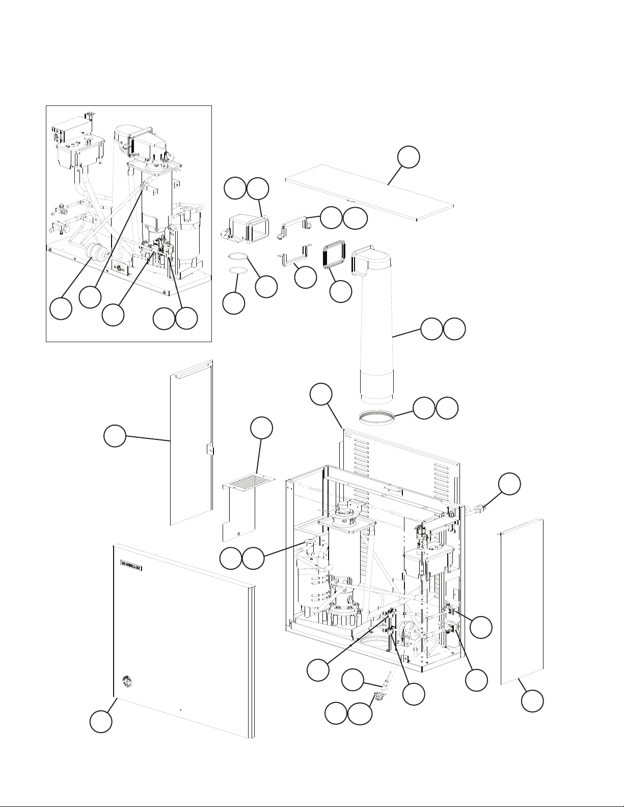
A. Main Assembly & Refrigeration Circuit
FS-1001MLJ-C
G-0, H-0
7a
7
11
2
11a
23
22
24
Rear View
4
27
28
8
9
6
2120
12
10
16 17
5
1918
15
26
30
1
4
14
13
14a
29
25
3
Page 5

Title: A. Main Assembly & Refrigeration Circuit Model: FS-1001MLJ-C
Index
No. Description
1 Front Panel 2A3145-01 1
2 Top Panel 2A3140-01 1
3 Right Side Panel 3A3328G01 1
4 Left Side Panel 3A3329G01 1
5 Rear Panel 1A2762-01 1
6 Control Box Cover 4A3675-01 1
7 Spout 104797-01 1
7a Thumbscrew 415949G08 3
8 O-Ring 4A4755-03 1
9 Nylon Ring 432661-02 1
10 Spout-to-Chute Packing 321037-01 1
11 Upper Strap 328703-02 1
11a Wing Nut 7E12-0600 2
12 Lower Strap 321038G02 1
13 Bin Control
(infrared sensor)
14 Bin Control Housing
(infrared sensor)
14a Thumbscrew 415949G10 1
15 Power Cord 4A1773-01 1
16 Chute 2A1919-03 1
17 Chute Insulation 2A1920-01 1
18 Chute Packing 432877-01 1
19 Ring 3A1017-01 1
Material or
Model Number Part Number
Main Assembly
4A4469-01 1
3A3478-01 1
G-0
H-0
Required Number
Refrigeration Circuit
20 Thermostatic Expansion Valve 4A3493-01 1
21 Thermostatic Expansion Valve
Cover
22 Clamp 4A5641-01 1
23 Drier 4A1338-01 1
24 Strainer 4A1385-01 1
25 Suction Line Shutoff Valve 4A3490-01 1
26 Liquid Line Shutoff Valve 4A3491-01 1
27 Liquid Line Valve Body 4A3276-01 1
28 Valve Coil 4A3277-01 1
29 Suction Line Service Valve 4A3420-01 1
30 Liquid Line Service Valve 1
4A1168-01 1
5
Page 6

B. Icemaking Unit
FS-1001MLJ-C
G-0, H-0
11
10
9
8
2
2a 2b
1
10a 10b
7
7b
7a
6
5
4a
7a
7b
4
4a
3
6
Page 7

Title: B. Icemaking Unit Model: FS-1001MLJ-C
Index
No. Description
1 Gear Motor 4A2007-01 1
2 Gear Motor Barrier 4A3441-01 1
2a Screw 7C32-0408 2
2b Washer 4A5268-01 2
3 Spline Coupling 414137-01 1
4 Housing 2A1977G01 1
4a Hex Head Bolt w/Washer 8×30, SS 7B0230830 6
5 O-Ring 4A4755-02 1
6 Mechanical Seal 432492-01 1
7 Evaporator 2A3314G01 1
7a Socket Head Cap Screw 8×12, SS 7S12-0812 4
7b Split Lock Washer M8, SS 7L22-0800 4
8 Evaporator Heater 4A2292-01 1
9 Auger 120863G02 1
10 Extruding Head 216530G07 1
10a Seal Bolt M8, SS P01768-02 4
10b Washer 427184-01 4
11 Cutter 427183G01 1
Material or
Model Number Part Number
Required Number
G-0
H-0
7
Page 8

C. Water Circuit
FS-1001MLJ-C
G-0, H-0
15
17
16
7
8
5
4
11
18
6
3
2
1
14
19
13
10
12
8
9
Page 9

Title: C. Water Circuit Model: FS-1001MLJ-C
Index
No. Description
1 Reservoir 2A0753-01 1
2 Reservoir Cover 214810-01 1
3 Float Switch 435490-01 1
4 Reservoir Separator 4A1255-01 1
5 Reservoir Inlet 4A0869-01 1
6 Water Supply Pipe 3A7478G01 1
7 Rubber Gasket 413854-03 1
8 Inlet Water Valve 4A5309-01 1
9 Silicone Hose L=575 mm 7730-1822 1
10 Reservoir Hose 4A1165-06 1
11 Vinyl Hose L=450 mm 7725-1923 1
12 Drain Fitting 4A5527-01 1
13 Vinyl Hose L=45 mm 7716-2025 1
14 Silicone Hose L=320 mm 7730I3896 1
15 Drain Valve 4A2772-01 1
16 Silicone Hose L=75 mm 7730I3896 1
17 Elbow 4A4316-01 1
18 Polyethylene Tube L=320 mm 4A4317L01 1
19 Drain Pan Assembly 3A3231G01 1
Hose Clamp 17-21 mm 4A2017-05 1
Hose Clamp 22-25 mm 4A2017-09 1
Hose Clamp 14-15 mm 4A2017-08 4
Material or
Model Number Part Number
Clamps
Required Number
G-0
H-0
9
Page 10

D. Control Box Assembly
FS-1001MLJ-C
G-0, H-0
10
9
8
1
2
3 4
5
6
10
7
7a
Page 11

Title: D. Control Box Assembly Model: FS-1001MLJ-C
Index
No. Description
1 Control Switch 4A0558-01 1
2 Power Switch 4A2332-01 1
3 Fuse Holder 4A5443-01 1
4 Control Board Fuse AGC-1A,
5 Fuse Holder 4A6101-01 1
6 Gear Motor Fuse GMD-3A,
7 Control Board 2A8054-01 1
7a Control Board Support 4A0336-03 4
8 Water Control Relay 406132-07 1
9 Gear Motor Capacitor 24MFD,
10 Control Transformer 4A0557-01 1
Material or
Model Number Part Number
4A0893-01 1
250VAC
4A0893-06 1
250VAC
Slow Blow
4A2273-01 1
250VAC
G-0
H-0
11
Page 12

E. Accessories & Labels
FS-1001MLH-C
G-0, H-0
1
2
Title: E. Accessories & Labels Model: FS-1001MLH-C
Index
No. Description
1 Hoshizaki Emblem Label 4A0560-01 1
2 Penguin Label 475552L02 1
3 Universal Bracket 4A3668-01 2
3a Hex Bolt 5×12, SS 7B02-0512 4
4 Self-Drilling Screw 7P11I1234 4
Material or
Model Number Part Number
Required Number
G-0
H-0
12
 Loading...