

Page 1
Hoshizaki
Hoshizaki America, Inc.
Modular Flaker
Serenity Series
Model
FS-1001MLH-C
“A Superior Degree
of Reliability”
www.hoshizaki.com
PARTS LIST
Number:
Issued: 5-23-2005
Revised: 7-18-2011
71233
Page 2

CONTENTS
Auxiliary Codes ...................................................................................................................... 3
Note About Ordering Parts .................................................................................................... 3
A. Ice Flaker Assembly .......................................................................................................... 4
B. Ice Making Unit .................................................................................................................. 7
C. Refrigeration Circuit ........................................................................................................... 9
D. Water Circuit .....................................................................................................................11
E. Control Box Assembly...................................................................................................... 13
F. Chute Assembly ............................................................................................................... 15
G. Label Location ................................................................................................................. 17
H. Accessories & Packaging ................................................................................................ 19
2
Page 3

Auxiliary Codes
FS-1001MLH-C
P-0 July 2004
Q-0 July 2005
S-0 February 2007
T-0 April 2008
T-1 October 2008
U-0 January 2009
U-1 December 2009
V-0 January 2010
V-1 February 2010
V-2 October 2010
V-3 November 2010
A-0 January 2011
Auxiliary Code Breakdown
The auxiliary code is the rst two characters in the serial number. The rst character
indicates the year. Years progress or regress in alphabetical order. The series runs from
"A" through "V" and the letters "I" and "O" are skipped. The second character indicates
signicant part changes within a year. Base is "0" and this number advances for each
change. In cases where there is a letter in parentheses, this designates the month. This is
the last character in the serial number. The series runs from "(A)" through "(M)" and the
letter "(I)" is skipped. This designation is only included when identifying a parts change
within an auxiliary code.
Note About Ordering Parts
Most assemblies cannot be ordered as complete units; parts in the assemblies generally
must be ordered separately.
3
Page 4
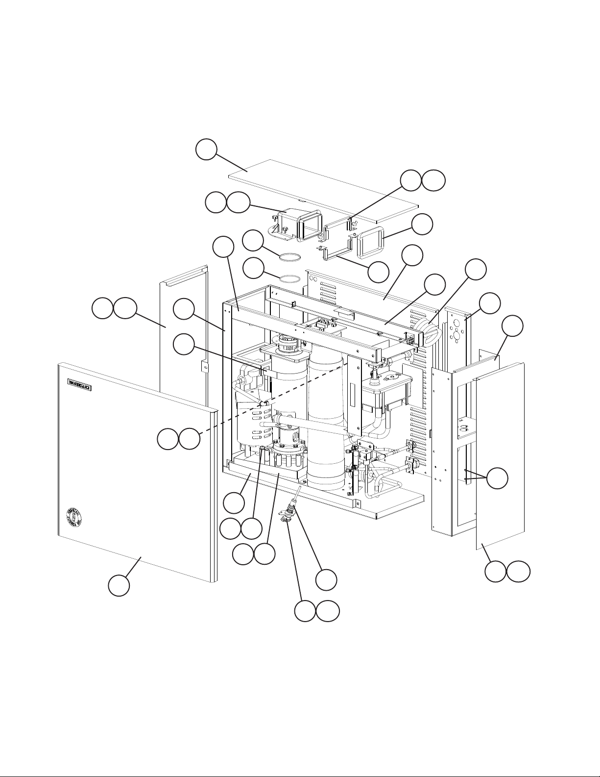
A. Ice Flaker Assembly
FS-1001MLH-C
P-0 to A-0
18
13
8
13a
10
11
14
15
15a
12
5
25
22
17
17a
19
21
9
3a
3
23
2
1
4a
4
20
24
16
7
6
16a
26
4
26a
Page 5
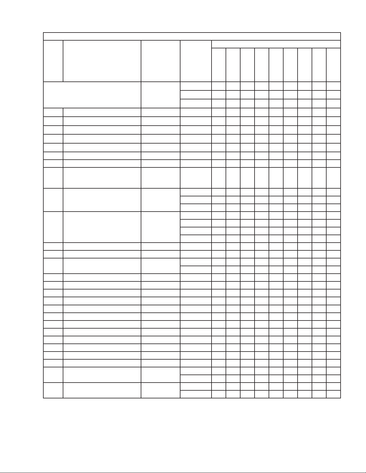
Title: A. Ice Flaker Assembly Model: FS-1001MLH-C
Required Number
P-0
P-0
Q-0
(G)
(M)
(K)
to
to
to
Index
No. Description
Ice Flaker Assembly
Order Assembly Parts Individually
1 Socket Head Cap Screw 8×90, SS 7S12-0890 3 3 3 3 3 3 3
2 Split Lock Washer M8, SS 7L22-0800 3 3 3 3 3 3 3
3 Taper Collar 4H0171-01 2 2 2 2 2 2 2
3a Flat Head Screw 4×8 7C21-0408 2 2 2 2 2 2 2
4 Drain Pan Assembly 3A3231G01 1 1 1 1 1 1 1
4a Hex Head Bolt 5×10, SS (LF) 7B02-0510 2 2 2 2 2 2 2
5 Rear Panel 2A3146-01 1 1 1 1 1 1 1
6 Hex Head Bolt w/ Washer
(Dispenser Unit/Storage Bin
Attachment Bolts)
7 Side Frame (R) 2A3138-01 1 -
8 Front Frame Assembly 3A3210G01 1 1 -
9 Evaporator Strap 4A3431-01 1 1 1 1 1 1 1
10 Ring 432661-02 1 1 1 1 1 1 1
11 "O" Ring 7616-G070 1 1 1 -
12 Spout Packing 321037-01 1 1 1 1 1 1 1
13 Spout 104797-01 1 1 1 1 1 1 1
13a Thumbscrew 415949G08 3 3 3 3 3 3 3
14 Lower Spout Strap 321038G02 1 1 1 1 1 1 1
15 Upper Spout Strap 328703-02 1 1 1 1 1 1 1
15a Wing Nut 6, SS 7E12-0600 2 2 2 2 2 2 2
16 Side Panel Assembly (R) 3A3328G01 1 1 1 1 1 1 1
16a Thumbscrew 415949G10 1 1 1 1 1 1 1
17 Side Panel Assembly (L) 3A3329G01 1 1 1 1 1 1 1
17a Thumbscrew 415949G10 1 1 1 1 1 1 1
18 Top Panel 2A3140-01 1 1 1 1 1 1 1
19 Front Panel 2A3145-01 1 1 1 1 1 1 1
20 Infrared Sensor-Bin Control 4A3773-01 1 1 1 1 -
21 Side Frame (L) 2A3139-01 1 1 1 1 1 -
Material or
Model Number
5×12, SS (LF) 7B0130512 4 4 4 4 4 4 4
Part
Number
1A0946A01 1 1 1 1 -
1A0946A02 1 -
1A1952A01 1 1
2A3395-01 1 1 1 1 2A5484-01 1 1
3A3816G01 1 3A5419-01 1 1 3A5814G01 1 1
4A4755-03 1 1 1 1
4A4469-01 1 1 1
2A5483-01 1 1
P-0
(L)
Q-0
(J)
U-0
(D)
U-0
(E)
U-1
V-0
V-1
(B)
to
V-1
(H)
V-1
(J)
to
A-0
5
Page 6
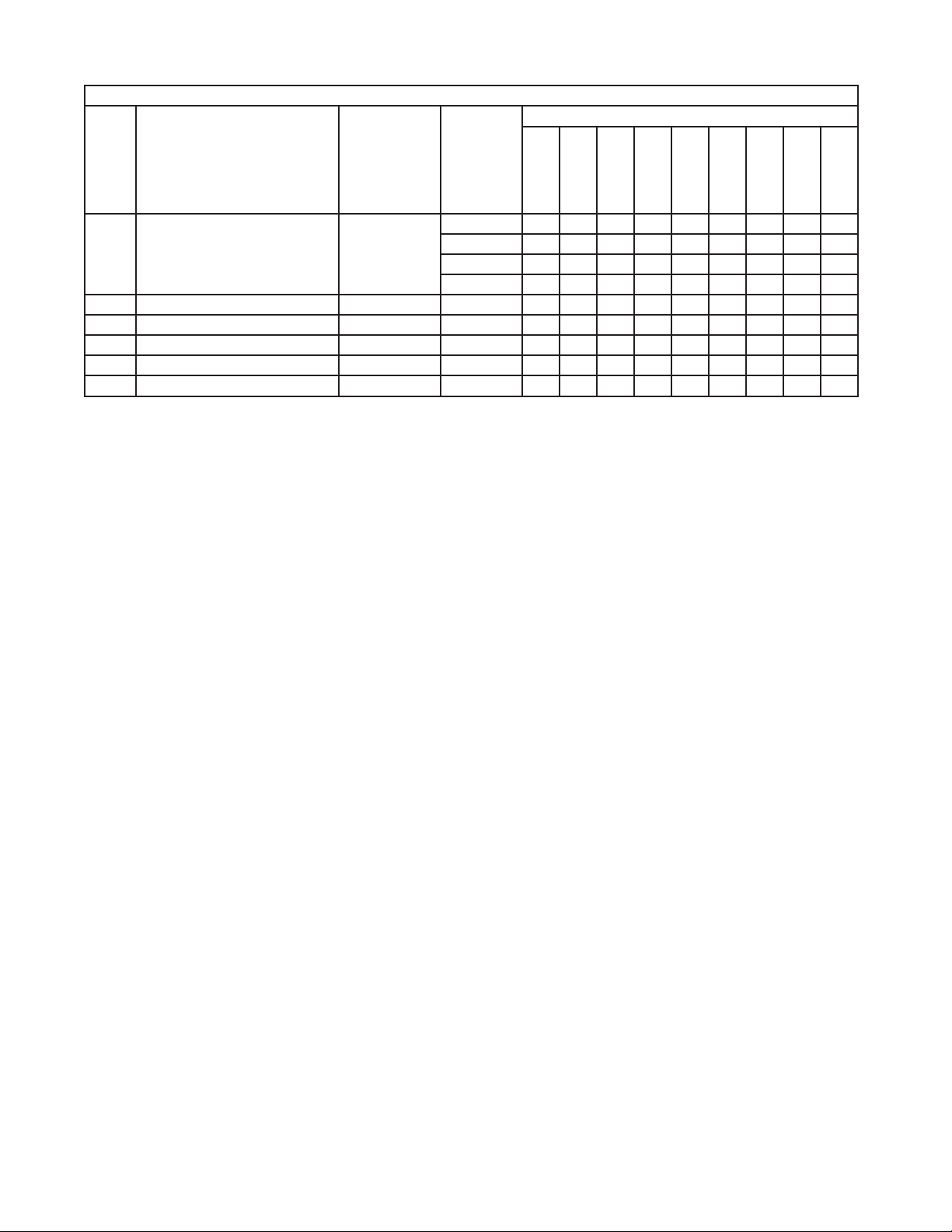
Title: A. Ice Flaker Assembly Model: FS-1001MLH-C
Required Number
P-0
P-0
Q-0
(G)
(M)
(K)
to
to
to
Index
No. Description
22 Rear Frame Assembly 3A3211G01 1 1 -
23 Front Bracket 3A3240-01 1 1 1 1 1 1 1
24 Rear Panel Cover 2A3396-01 1 1 1 1 1 1 1
25 Power Cord 4A1773-01 1 1 1 1 1 1 1
26 Infrared Sensor Housing 3A3478-01 1 1 1 1 1 1 1
26a Thumbscrew 415949G10 1 1 1 1 1 1 1
Material or
Model Number
Part
Number
3A3815G01 1 3A5418-01 1 1 3A5813G01 1 1
P-0
(L)
Q-0
(J)
U-0
(D)
U-0
(E)
U-1
V-0
V-1
(B)
to
V-1
(H)
V-1
(J)
to
A-0
6
Page 7

B. Ice Making Unit
FS-1001MLH-C
P-0 to A-0
13a
13
14
5
12
10
12b
3
4
12a
11
11a
11b
9
8
7
2
7a 7b 7c
1
6
7
Page 8

Title: B. Ice Making Unit Model: FS-1001MLH-C
Required Number
T-1
U-0
P-0
to
(E)
Index
No. Description
Ice Making Unit
Order Assembly Parts Individually
1 Gear Motor (for mounting
hardware, see section "A" items
1 and 2)
2 Gear Motor Barrier 4A3441-01 1 1 1 1 1
3 Heater 4A2292-01 1 1 1 1 1
4 Spring 4A2292F01 1 1 1 1 1
5 Washer 4A3418-01 1 1 1 1 1
6 Spline Coupling 414137-01 1 1 1 1 1
7 Housing 2A1977G01 1 1 1 1 1
7a Hex Head Bolt 8×30, SS 7B02-0830 6 6 6 6 6
7b Flat Washer M8, SS 7W22-0800 6 6 6 6 6
7c Split Lock Washer M8, SS 7L22-0800 6 6 6 6 6
8 "O" Ring 7616-G065 1 1 -
9 Mechanical Seal 432492-01 1 1 1 1 1
10 Auger 2A2151G03 1 -
11 Evaporator 2A1733G01 1 1 1 1 1
11a Socket Head Cap Screw 8×12, SS 7S12-0812 4 4 4 4 4
11b Split Lock Washer M8, SS 7L22-0800 4 4 4 4 4
12 Extruding Head 216530G04 1 1 1 1 1
12a Seal Bolt M8, SS P01768-01 4 4 4 4 4
12b Washer 427184-01 4 4 4 4 4
13 Cutter 4A3443G02 1 1 1 1 1
13a Hex Head Bolt 10×40, SS 7B02-1040 1 1 1 1 1
14 Dowel Pin 713S-0416 1 1 1 1 1
Material or
Model Number Part Number
3A3157A01 1 1 1 1 1
4A2007-01 1 1 1 1 1
4A4755-02 1 1 1
1A1541G02 1 1 1A2037G02 1 120863G02 1
T- 0
to
U-0
(D)
to
V-1 V-2
V-3
A-0
8
Page 9

C. Refrigeration Circuit
FS-1001MLH-C
P-0 to A-0
2
3
4
5
7 8
6
1
8a
1211
109
13
9
Page 10

Title: C. Refrigeration Circuit Model: FS-1001MLH-C
P-0
to
Index
No. Description
Refrigeration Circuit
Order Assembly Parts Individually
1 Drier 4A1338-01 1 1
2 Expansion Valve 4A3493-01 1 1
3 Expansion Valve Cover 4A1168-01 1 1
4 Expansion Valve Bulb Holder 3A0112-01 1 1
5 Clamp 443461-01 1 1
6 Service Valve 4A3420-01 2 2
7 Line Valve Body 440352-01 1 -
8 Valve Coil 440353-01 1 -
8a Bolt 440353F01 1 -
9 Coupling 434072-01 1 1
10 Tube Holder-L 438245-01 1 1
11 Coupling 426554-01 1 1
12 Tube Holder-S 438246-01 1 1
13 Strainer 4A1385-01 1 1
Material or
Model Number Part Number
1A0947A01 1 1
4A3276-01 1
4A3277-01 1
4A3277F01 1
Q-0
(J)
Required Number
Q-0
(K)
to
A-0
10
Page 11

D. Water Circuit
FS-1001MLH-C
P-0 to A-0
9
19
18
20
16
7
6
8
3
5
2
1
4
12
21
17
11
10
15
13
14
11
Page 12

Title: D. Water Circuit Model: FS-1001MLH-C
Q-0
P-0
(K)
to
to
Index
No. Description
Water Circuit
Order Assembly Parts Individually
1 Reservoir 2A0753-01 1 1 1
2 Reservoir Cover 214810-01 1 1 1
3 Float Switch 435490-01 1 1 1
4 Reservoir Separator 4A1255-01 1 1 1
5 Reservoir Inlet 4A0869-01 1 1 1
6 Water Supply Pipe 3A3161G01 1 1 1
7 Washer 4A0867-01 1 1 1
8 Inlet Water Valve 4A0865-01 1 1 1
9 Inlet Water Valve Bracket 4A3728-01 1 1 1
10 Silicone Hose L=575mm 7730-1822 1 1 1
11 Reservoir Hose 4A1165-06 1 1 1
12 Vinyl Hose L=450mm 7725-1923 1 1 1
13 Fitting 4A0776G01 1 1 1
14 Vinyl Hose L=45mm 7716-2025 1 1 1
15 Drain Fitting Bracket 4A3447-01 1 1 1
16 Drain Valve Bracket 4A3667-01 1 1 1
17 Vinyl Hose L=320mm 7716-1216 1 -
Silicone Hose 7730I3896 1 1
18 Drain Valve 4A2772-01 1 1 1
19 Vinyl Hose L=65mm 7716-0913 1 -
20 Elbow 4A3671-01 1 1 -
21 Reservoir Tube L=320mm 4A3672-01 1 1 -
Polyethylene Tube 4A4317L01 1
Hose Clamp 17.1 - 20.6mm 4A2017-05 1 1 1
Hose Clamp 22.2 - 25.4mm 4A2017-09 5 5 5
Hose Clamp 13.5 - 15.1mm 4A2017-08 2 2 2
Material or
Model Number Part Number
2A3137A01 1 1 2A3137A02 1
L=115mm 7716-1216 1 1
4A4316-01 1
Clamps
Q-0
(J)
S-0
(F)
Required Number
S-0
(G)
to
A-0
12
Page 13

E. Control Box Assembly
FS-1001MLH-C
P-0 to A-0
13
10
8
9
12
14
13a
P-0 to U-0
1
11
2
3 4
5
7 7a
6
10
12
13a
U-1 to A-0
13
1
11
2
3 4
5
7 7a
6
13
Page 14

Title: E. Control Box Assembly Model: FS-1001MLH-C
P-0
Q-0
to
(K)
U-1
Index
No. Description
Control Box Assembly
Order Assembly Parts Individually
(for mounting hardware, see section
"A" items 4 and 4a)
1 Rocker Switch (Flush) 4A0558-01 1 1 1 1
2 Toggle Switch (Power) 4A2332-01 1 1 1 1
3 Fuse Holder 4A0892-01 1 1 1 -
4 Control (Timer) Board Fuse 1A, 250VAC 4A0893-01 1 1 1 1
5 Fuse Holder 4A0892-02 1 1 1 -
6 Gear Motor Fuse 3A, 250VAC 4A0893-06 1 1 1 1
7 Control (Timer) Board 437305-01 1 1 -
7a Board Support 4A0336-03 4 4 4 4
8 Water Control Relay 406132-03 1 1 9 Cam Timer 4A2157-01 1 1 -
10 Gear Motor Capacitor 24MFD,
11 Control Transformer 4A0557-01 1 1 1 1
12 Gear Motor Protect Relay 406132-07 1 1 -
13 Control Box Cover 4A3675-01 1 1 1 1
13a Thumbscrew 415949G10 1 1 1 1
14 Time Delay Relay 4A3761-01 1 -
Material or
Model Number Part Number
3A3501A01 1 1 -
3A5547A01 1 1
4A3449-01 1
4A3449-02 1
2A4296-01 1 1
4A2273-01 1 1 1 1
250VAC
418271-03 1 1
4A3940-01 1 -
Q-0
(J)
to
U-0
to
V-3 A-0
14
Page 15

F. Chute Assembly
FS-1001MLH-C
P-0 to A-0
10a
10
12a
12
13
11
6
5a
9
8
5
7
4
4a
3
1
2
15
Page 16

Title: F. Chute Assembly Model: FS-1001MLH-C
P-0
to
Index
No. Description
Chute Assembly
Order Assembly Parts Individually
1 Chute 2A1919-01 1 1
2 Chute Insulation 2A1920-01 1 1
3 Tie 436531G01 3 3
4 Chute Baffle A 3A0400G01 1 1
4a Wing Nut 4, SS 7E12-0400 3 3
5 Chute Baffle B 3A0399G01 1 1
5a Wing Nut 4, SS 7E12-0400 3 3
6 Bin Control Bracket 3A1744G01 1 1
7 Actuator 436848G01 1 1
8 Shaft 436851-01 1 1
9 Snap Pin 715S-0005 2 2
10 Mechanical Bin Control
Proximity Switch
10a Thumbscrew 415949G08 2 2
11 Packing 441217-01 1 12 Plate 4A2039-01 1 1
12a Thumbscrew 415949G10 2 2
13 Ground Screw 4×8, SS 7C32-0408 1 1
Material or
Model Number Part Number
HS-2024 2A1705A04 1 1
4A2033-01 1 1
T- 0
(E)
Required Number
T- 0
(F)
to
A-0
16
Page 17

G. Label Location
FS-1001MLH-C
P-0 to A-0
9
7
10
4
2
13
1
5
8
11
6
12
3
17
14
Page 18

Title: G. Label Location Model: FS-1001MLH-C
P-0
T-0
Index
No. Description
Label Location
Order Assembly Parts Individually
1 Instruction Sheet 2A3222-01 1 1 2 Emblem 4A0560-01 1 1 1
3 Penguin-HA-R Label 4A0526-01 1 1 1
4 Cleaning Label 2A3445-01 1 1 1
5 Nameplate 3A3241-01 1 1 1
6 Rating Label 3A3242-01 1 1 1
7 Control Label 4A2234-01 1 1 1
8 R-404A Label 4A0960-01 1 1 9 Wiring Label 3A3505-01 1 1 -
10 Caution Label 4A3932-01 1 1 1
11 Fuse Label (GM) 4A2835-01 1 -
12 Caution Label (E) 439145-01 1 1 1
13 Instruction Label 326371-01 1 1 1
14 Instruction Sheet 433523-01 1 1 1
Material or
Model Number
Part
Number
2A3180A01 1 1 1
3A5548-01 1
4A4278-01 1 1
to
S-0
to
U-0
Required Number
U-1
to
A-0
18
Page 19

H. Accessories & Packaging
FS-1001MLH-C
P-0 to A-0
Title: H. Accessories & Packaging Model: FS-1001MLH-C
Index
No. Description
1 Instruction Manual 91A2PB10B 1
2 Bracket 4A3668-01 2
2a Hex Bolt 5×12, SS 7B02-0512 4
2b Self-Tapping Bolts 7P11I1234 4
Packaging 1A1046A01
Material or
Model Number Part Number
Required Number
P-0
to
A-0
19
 Loading...