

Page 1

Hoshizaki
Hoshizaki America, Inc.
Commercial Series
Refrigerated Kitchen Equipment
Models
CR1B-FG/FS/HS
“A Superior Degree
of Reliability”
www.hoshizaki.com
CF1B-FG/FS/HS
CR2B-FG/FS/HS
CF2B-FG/FS/HS
CR3B-FS/HS
CF3B-FS/HS
PARTS LIST
Number: 71344
Issued: 3-20-2012
Revised: 5-7-2012
Page 2

CONTENTS
Auxiliary Codes ...................................................................................................................... 3
Note About Ordering Parts .................................................................................................... 3
A. Main Assembly .................................................................................................................. 4
CR1B-FG/FS/HS, CF1B-FG/FS/HS .................................................................................. 4
CR2B-FG/FS/HS, CF2B-FG/FS/HS .................................................................................. 6
CR3B-FS/HS, CF3B-FS/HS .............................................................................................. 8
B. Refrigeration Circuit ......................................................................................................... 10
CR1B-FG/FS/HS, CR3B-FS/HS ...................................................................................... 10
CF1B-FG/FS/HS, CF3B-FS/HS ...................................................................................... 12
CR2B-FG/FS/HS, CR3B-FS/HS ...................................................................................... 14
CF2B-FG/FS/HS, CF3B-FS/HS ...................................................................................... 16
C. Control Box Assembly ..................................................................................................... 18
CR1B-FG/FS/HS, CF1B-FG/FS/HS, CR2B-FG/FS/HS, CR3B-FS/HS, CF3B-FS/HS .... 18
CF2B-FG/FS/HS, CF3B-FS/HS ...................................................................................... 19
D. Door-Right Hinged ........................................................................................................... 20
Full Glass: CR1B-FG, CF1B-FG, CR2B-FG, CF2B-FG .................................................. 20
Full Solid: CR1B-FS, CF1B-FS, CR2B-FS, CF2B-FS, CR3B-FS, CF3B-FS ................... 21
Half Solid: CR1B-HS, CF1B-HS, CR2B-HS, CF2B-HS, CR3B-HS, CF3B-HS ................ 22
E. Door-Left Hinged ............................................................................................................. 24
Full Glass: CR2B-FG, CF2B-FG ..................................................................................... 24
Full Solid: CR2B-FS, CF2B-FS, CR3B-FS, CF3B-FS ..................................................... 25
Half Solid: CR2B-HS, CF2B-HS, CR3B-HS, CF3B-HS ................................................... 26
F. Accessories & Packaging ................................................................................................. 28
2
Page 3
Auxiliary Codes
CR1B-FG
A-5 September 2011
B-5 January 2012
B-6 May 2012
CR1B-FS
V-5 December 2010
A-5 February 2011
B-5 January 2012
B-6 May 2012
CR1B-HS
A-5 February 2011
B-5 January 2012
B-6 May 2012
CF1B-FG
B-5 January 2012
B-6 May 2012
CF1B-FS
A-5 January 2011
B-5 January 2012
B-6 May 2012
CF1B-HS
A-5 February 2011
B-5 February 2012
B-6 May 2012
CR2B-FG
A-5 October 2011
B-6 May 2012
CR2B-FS
V-5 December 2010
A-5 February 2011
B-5 January 2012
B-6 May 2012
CR2B-HS
A-5 February 2011
B-5 January 2012
B-6 May 2012
CF2B-FG
B-6 May 2012
CF2B-FS
A-5 January 2011
B-5 January 2012
B-6 May 2012
CF2B-HS
A-5 February 2011
B-6 May 2012
CR3B-FS
A-5 February 2011
B-5 January 2012
B-6 May 2012
CR3B-HS
A-5 March 2011
B-5 April 2012
B-6 May 2012
CF3B-FS
A-5 January 2011
B-5 January 2012
B-6 May 2012
CF3B-HS
B-6 May 2012
Beginning Serial Numbers for Control Module Change
CR1B-FG B50031B
CR1B-FS B50602B
CR1B-HS B50046B
CF1B-FG B50004D
CF1B-FS B50482C
CF1B-HS B50101B
CR2B-FG B6 and later
CR2B-FS B50722C
CR2B-HS B50011B
CF2B-FS B50642B
CF2B-HS B6 and later
CR3B-FS B50082C
CR3B-HS B50001D
CF3B-FS B50053B
CF3B-HS B6 and later
Auxiliary Code Breakdown
The auxiliary code is the rst two characters in the serial number. The rst character indicates the year. Years progress
or regress in alphabetical order. The series runs from "A" through "V" and the letters "I" and "O" are skipped. The second
character indicates signicant part changes within a year. Base is "5" and this number advances for each change. In cases
where there is a letter in parentheses, this designates the month. This is the last character in the serial number. The series
runs from "(A)" through "(M)" and the letter "(I)" is skipped. This designation is only included when identifying a parts
change within an auxiliary code.
Note About Ordering Parts
Most assemblies cannot be ordered as complete units; parts in the assemblies generally must be ordered separately.
3
Page 4
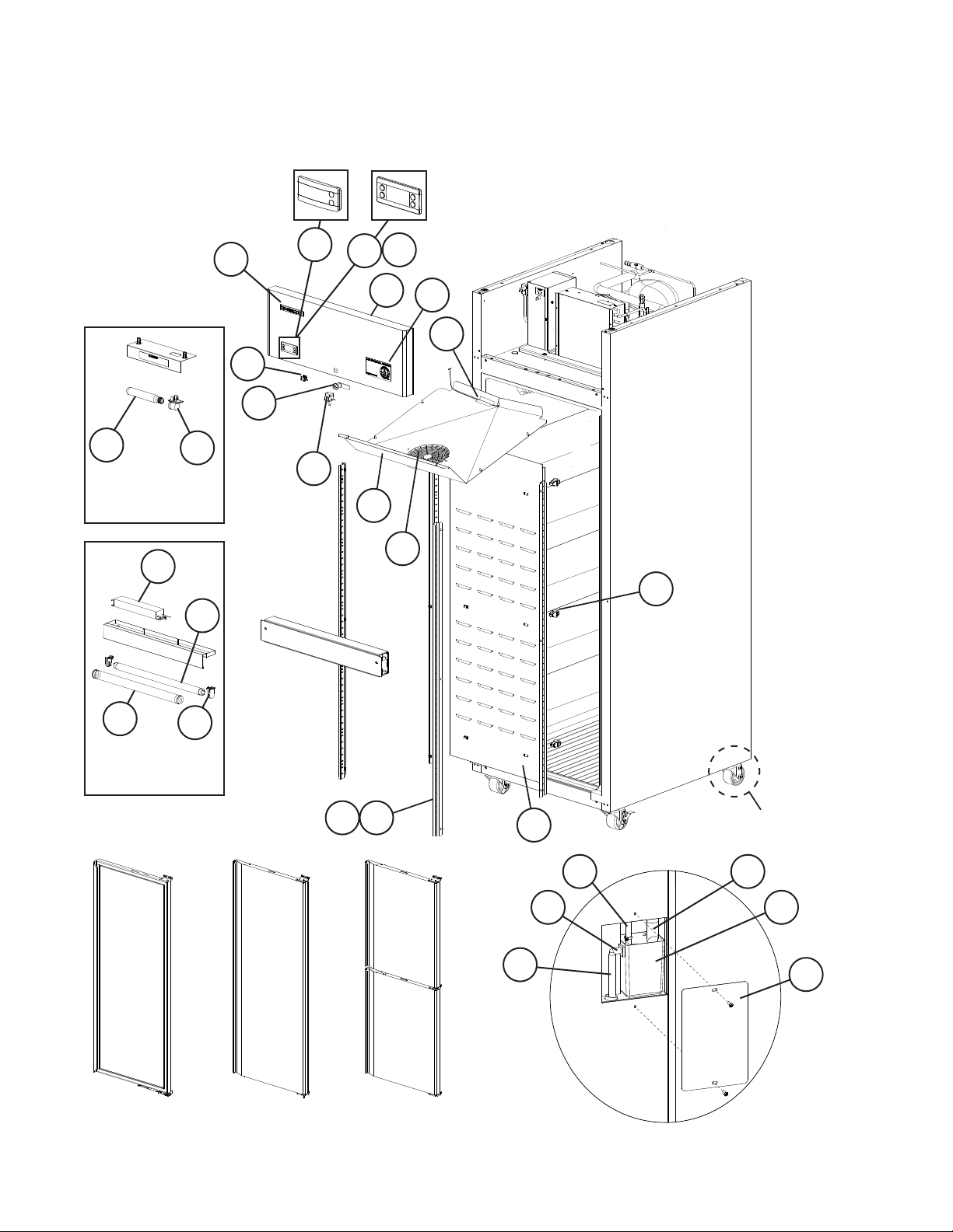
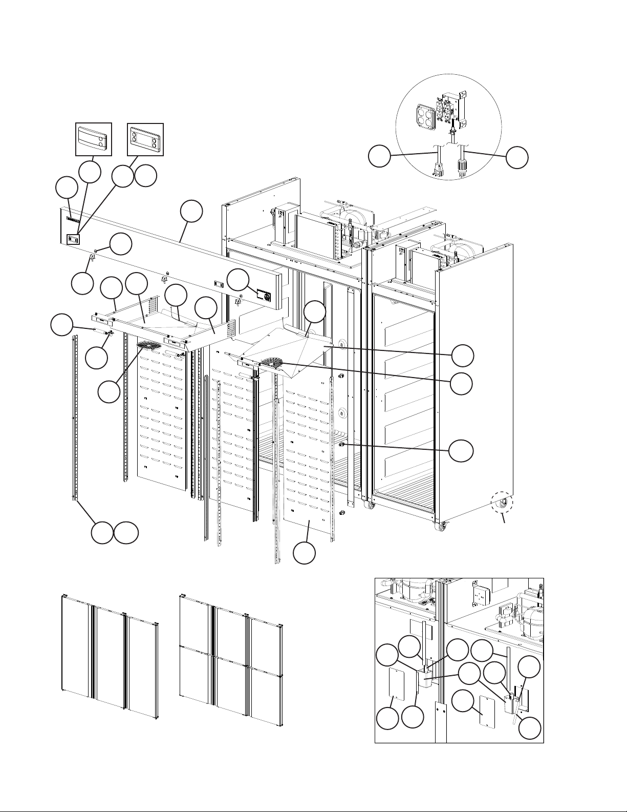
A. Main Assembly
CR1B-FG/FS/HS, CF1B-FG/FS/HS
V-5 to B-6
B-5(A) and
Earlier
B-5(B)
and Later
15
Incandescent Light
Assembly for Solid
Door Models
14
13
11
7
2
2a
2
1
6
17
4
5
3
16
18
8a
12
Fluorescent Light
Assembly for Glass
Door Models
Full Glass
10
For Doors, see Section "D"
Full Solid
9
9a
Half Solid
8
For Casters, see
Section "F"
2223
21
24
For Float Switch, see Condensate
Water Pump in Section "B"
20
19
4
Page 5
Title: A. Main Assembly Models: CR1B-FG/FS/HS, CF1B-FG/FS/HS
A-5
V-5
(G)
to
to
Index
No. Description
Main Assembly
Order Assembly Parts Individually
Assembly Number for Reference Only
Material or
Model Number Part Number
A-5
(F)
B-5
(A)
CR1B-FG 1A2295A01 1 1 1
CR1B-FS 1A2173A01 1 1 1
CR1B-HS 1A2174A01 1 1 1
CF1B-FG 1A2333A01 1 1
CF1B-FS 1A2175A01 1 1 1
CF1B-HS 1A2176A01 1 1 1
1 Front Panel CR1B-FG
2A6705-01 1 1 1
CF1B-FG
CR1B-FS/HS
2A5219-01 1 1 1
CF1B-FS/HS
2 Display Module (includes
4A4862-01 1 1 - See Page 3 for Exact Beginning
mounting clips)
Control Module
CR1B-FG/FS/HS
CF1B-FG/FS/HS
4A5500G01 1 Earlier Aux Codes: See "C. Control
4A5501G01 1
2a Control Module Mounting Clip 4A5502-01 2
3 Door Switch 3A1826-01 1 1 1
4 Fluorescent Light Switch CR1B-FG
4A0418-01 1 1 1
CF1B-FG
5 Lock (includes 2 keys) 4A4924-01 1 1 1
6 Commercial Label
CR1B-FG/FS/HS
CF1B-FG/FS/HS
3A5816-01 1 1 1
3A5816-02 1 1 1
7 Hoshizaki Emblem Label 4A0560-01 1 1 1
8 Rear Duct Panel 2A5205-01 1 1 1
8a Duct Stand Off 4A4874-01 6 6 6
9 Pilaster 3A0145-22 4 4 4
9a Truss Head Screw 5×10, SS 7C32-0510 12 12 12
10 Fluorescent Light Mount CR1B-FG
11 Fluorescent Light Bulb 4A4347-02 1 1 1
CF1B-FG
4A4346-01 2 2 2
12 Fluorescent Light Bulb Guard 4A4348-02 1 1 1
13 Fluorescent Light Ballast 4A4350-01 1 1 1
14 Incandescent Light Socket CR1B-FS/HS
15 Incandescent Light Bulb 4A4444-01 1 1 1
CF1B-FS/HS
4A4443-01 1 1 1
16 Evaporator Fan Shroud 3A6446G01 1 1 1
17 Drain Heater
CF1B-FG/FS/HS
4A2975-05 1 1
18 Evaporator Fan Guard 4A4860-01 1 1 1
19 Reservoir Cover 3A5898-01 1 1 1
20 Drain Reservoir 3A5565-01 1 1 1
21 Drain Fitting 4A2792-01 1 1 1
22 Drain Boot 4A4938-01 1 1 1
23 PVC Tubing L=650 7716I1438 1 1 1
24 Silicone Hose L=150 7730I3812 1 1 1
Required Number
B-5
(B)
to
B-6
Serial Numbers for Control Module
Change
Box Assembly" for Control Module
5
Page 6
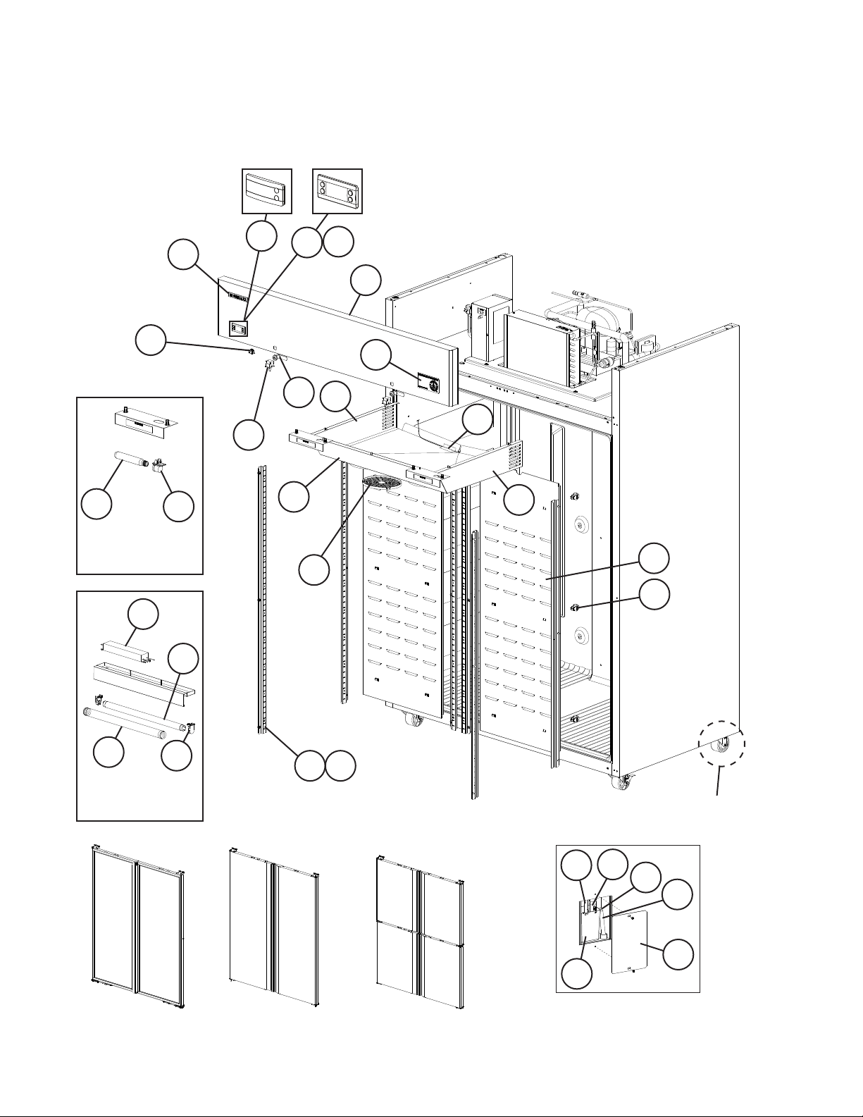
A. Main Assembly
CR2B-FG/FS/HS, CF2B-FG/FS/HS
V-5 to B-6
B-5(A) and
Earlier
B-5(B)
and Later
7
4
15
Incandescent Light
Assembly for Solid
Door Models
14
13
2
2a
2
1
6
5
19
17
3
16
18
8
20
8a
11
12
Fluorescent Light
Assembly for Glass
Door Models
Full Glass
10
For Doors, see Sections "D" and "E"
Full Solid
9
9a
For Casters, see
Section "F"
24
25
23
26
21
22
Half Solid
For Float Switch, see Condensate
Water Pump in Section "B"
6
Page 7
Title: A. Main Assembly Models: CR2B-FG/FS/HS, CF2B-FG/FS/HS
A-5
V-5
(G)
to
to
Index
No. Description
Main Assembly
Order Assembly Parts Individually
Assembly Number for Reference Only
Material or
Model Number Part Number
A-5
(F)
B-5
(A)
CR2B-FG 1A2304A01 1 1 1
CR2B-FS 1A2178A01 1 1 1
CR2B-HS 1A2180A01 1 1 1
CF2B-FG 1A2459A01 1
CF2B-FS 1A2182A01 1 1 1
CF2B-HS 1A2184A01 1 1 1
1 Front Panel CR2B-FG 2A6706-01 1 1
CR2B-FS/HS
2A5884-01 1 1 1
CF2B-FS/HS
2 Display Module (includes
4A4862-01 1 1 - See Page 3 for Exact Beginning
mounting clips)
Control Module
CR2B-FG/FS/HS
CF2B-FG/FS/HS
4A5500G01 1 Earlier Aux Codes: See "C. Control
4A5501G01 1
2a Control Module Mounting Clip 4A5502-01 2
3 Door Switch 3A1826-01 2 2 2
4 Fluorescent Light Switch CR2B-FG
4A0418-01 1 1 1
CF2B-FG
5 Lock (includes 2 keys) 4A4924-01 2 2 2
6 Commercial Label
CR2B-FG/FS/HS
CF2B-FG/FS/HS
3A5816-01 1 1 1
3A5816-02 1 1 1
7 Hoshizaki Emblem Label 4A0560-01 1 1 1
8 Rear Duct Panel 2A5205-01 2 2 2
8a Duct Stand Off 4A4874-01 12 12 12
9 Pilaster 3A0145-22 8 8 8
9a Truss Head Screw 5×10, SS 7C32-0510 24 24 24
10 Fluorescent Light Mount CR2B-FG
11 Fluorescent Light Bulb 4A4347-02 2 2 2
CF2B-FG
4A4346-01 4 4 4
12 Fluorescent Light Bulb Guard 4A4348-02 2 2 2
13 Fluorescent Light Ballast 4A4350-01 1 1 1
14 Incandescent Light Socket CR2B-FS/HS
15 Incandescent Light Bulb 4A4444-01 2 2 2
CF2B-FS/HS
4A4443-01 2 2 2
16 Evaporator Fan Shroud 3A6212G01 1 1 1
17 Drain Heater
18 Right Evaporator Fan Shroud
CF2B-FG/FS/HS
4A2975-05 1 1
3A6629G01 1 1 1
Side
19 Left Evaporator Fan Shroud
3A6638G01 1 1 1
Side
20 Evaporator Fan Guard 4A4860-01 3 3 3
21 Reservoir Cover 3A5898-01 1 1 1
22 Drain Reservoir 3A5565-01 1 1 1
23 Drain Fitting 4A2792-01 1 1 1
24 Drain Boot 4A4938-01 1 1 1
25 PVC Tubing L=860 7716I1438 1 1 1
26 Silicone Hose L=150 7730I3812 1 1 1
Required Number
B-5
(B)
to
B-6
Serial Numbers for Control Module
Change
Box Assembly" for Control Module
7
Page 8
A. Main Assembly
CR3B-FS/HS, CF3B-FS/HS
A-5 to B-6
B-5(A) and
Earlier
B-5(B)
and Later
10
22
2
2a
2
CR3B-FS/HS
22
CF3B-FS/HS
6
1
4
3
14
11
12
13
9
15
5
12
11
15
7a
8a
8
Half SolidFull Solid
For Doors, see Sections "D" and "E"
For Casters, see
Section "F"
7
20
18
19
17
20
19
18
16
21
16
21
For Float Switch, see Condensate
Water Pump in Section "B"
8
Page 9
Title: A. Main Assembly Models: CR3B-FS/HS, CF3B-FS/HS
A-5
(G)
to
Index
No. Description
Main Assembly
Order Assembly Parts Individually
Assembly Number for Reference Only
1 Front Panel 2A6416-01 1 1 1
2 Display Module (includes
mounting clips)
Control Module CR3B-FS/HS 4A5500G01 2 Earlier Aux Codes: See "C. Control
2a Control Module Mounting Clip 4A5502-01 4
3 Door Switch 3A1826-01 3 3 3
4 Lock (includes 2 keys) 4A4924-01 3 3 3
5 Commercial Label CR3B-FS/HS 3A5816-01 1 1 1
6 Hoshizaki Emblem Label 4A0560-01 1 1 1
7 Rear Duct Panel 2A5205-01 3 3 3
7a Duct Stand Off 4A4874-01 18 18 18
8 Pilaster 3A0145-22 12 12 12
8a Truss Head Screw 5×10, SS 7C32-0510 36 36 36
9 Incandescent Light Socket 4A4443-01 3 3 3
10 Incandescent Light Bulb 4A4444-01 3 3 3
11 Evaporator Fan Shroud: One
Section
Evaporator Fan Shroud: Two
Section
12 Drain Heater CF3B-FS/HS 4A2975-05 2 2
13 Right Evaporator Fan Shroud
Side
14 Left Evaporator Fan Shroud
Side
15 Evaporator Fan Guard 4A4860-01 4 4 4
16 Reservoir Cover 3A5898-01 2 2 2
17 Drain Reservoir 3A5565-01 2 2 2
18 Drain Fitting 4A2792-01 2 2 2
19 Drain Boot 4A4938-01 2 2 2
20 PVC Tubing: One Section L=650 7716I1438 1 1 1
PVC Tubing: Two Section L=860 7716I1438 1 1 1
21 Silicone Hose L=150 7730I3812 2 2 2
22 Power Cord CR3B-FS/HS 4A5379-01 1 1 1
Material or
Model Number Part Number
CR3B-FS 1A2148A01 1 1 1
CR3B-HS 1A2152A01 1 1 1
CF3B-FS 1A2150A01 1 1 1
CF3B-HS 1A2154A01 1
4A4862-01 2 2 - See Page 3 for Exact Beginning
CF3B-FS/HS 4A5501G01 2
CF3B-FS/HS 3A5816-02 1 1 1
3A6446G01 1 1 1
3A6212G01 1 1 1
3A6629G01 1 1 1
3A6638G01 1 1 1
CF3B-FS/HS 4A5318-01 1 1 1
A-5
(A-F)
B-5
(A)
Required Number
B-5
(B)
to
B-6
Serial Numbers for Control Module
Change
Box Assembly" for Control Module
9
Page 10

B. Refrigeration Circuit
CR1B-FG/FS/HS, CR3B-FS/HS
V-5 to B-6
4
10
17
3
15
16
13
18
1
1a 1b
12
6
6a
14
2
1c
11
5
7 7a
8
20
21
19
9
10
Page 11

Title: B. Refrigeration Circuit Model: CR1B-FG/FS/HS, CR3B-FS/HS
A-5
V-5
(H)
to
to
Index
No. Description
Refrigeration Circuit
Order Assembly Parts Individually
Assembly Number for Reference Only
1 Compressor 4A3177-01 1 1 1
1a Rubber Grommet 4A1452-01 4 4 4
1b Compressor Clip 4A4867-01 4 4 4
1c Screw 4A4993-01 4 4 4
2 Start Relay 4A2135-03 1 1 1
3 Start Capacitor 280MFD,
4 Condenser 2A6415-01 1 1 1
5 Condenser Fan Guard 2A5187-01 1 1 1
6 Condenser Fan Motor 4A4869-01 1 1 -
6a Self-Locking Nut 8-32 7N21I0832 4 4 4
7 Condenser Fan Blade 3A5817-01 1 1 1
7a Washer 3A6852-01 1 1
8 Condensate Coil 3A6465G01 1 1 1
9 Evaporator 2A6463-01 1 1 1
10 Defrost Thermistor 4A4865-02 1 1 1
11 Thermistor Clip 4A3248G01 1 1 1
12 Evaporator Fan 4A5343-01 2 2 2
13 Drier 4A1113-01 1 1 1
14 High-Pressure Switch 4A2516-01 1 1 1
15 Thermostatic Expansion Valve 4A4597-01 1 1 1
16 Thermostatic Expansion Valve
Cover
17 Thermostatic Expansion Valve
Bulb Holder
18 Clamp 443461-01 1 1 1
19 Condensate Water Pump
(includes oat switch)
20 PVC Tubing L=350 7716I1438 1 1 1
21 Cabinet Thermistor 4A4864-01 1 1 1
Material or
Model Number Part Number
1A2160A01 1 1 1
4A2134-01 1 1 1
125/165VAC
4A5498-01 1
4A4646-01 1 1 1
3A0107-01 1 1 1
3A6339G01 1 1 1
A-5
(G)
B-5
(A)
Required Number
B-5
(B)
to
B-6
11
Page 12

B. Refrigeration Circuit
CF1B-FG/FS/HS, CF3B-FS/HS
A-5 to B-6
4
10
16
17
14
18 19
6
13
15
1c
1b
1a
1
2
6a
5
7 7a
8
3
21
20
22
9
12
12
11
Page 13

Title: B. Refrigeration Circuit Model: CF1B-FG/FS/HS, CF3B-FS/HS
A-5
(H)
to
Index
No. Description
Refrigeration Circuit
Order Assembly Parts Individually
Assembly Number for Reference Only
1 Compressor 4A3808-01 1 1 1
1a Rubber Grommet 4A1452-01 4 4 4
1b Compressor Clip 4A4867-01 4 4 4
1c Screw 4A4993-01 4 4 4
2 Start Relay 4A3113-01 1 1 1
3 Start Capacitor 240MFD,
4 Condenser 2A6415-01 1 1 1
5 Condenser Fan Guard 2A5187-01 1 1 1
6 Condenser Fan Motor 4A4869-01 1 1 -
6a Self-Locking Nut 8-32 7N21I0832 4 4 4
7 Condenser Fan Blade 3A5817-01 1 1 1
7a Washer 3A6852-01 1 1
8 Condensate Coil 3A6465G01 1 1 1
9 Evaporator 2A6463-01 1 1 1
10 Defrost Thermistor 4A4865-01 1 1 1
11 Defrost Heater 2A5378-01 1 1 1
12 Defrost Thermostat 4A0954-02 1 1 1
13 Evaporator Fan 4A5343-01 2 2 2
14 Drier 4A1113-01 1 1 1
15 High-Pressure Switch 4A2516-02 1 1 1
16 Thermostatic Expansion Valve 4A5344-01 1 1 1
17 Thermostatic Expansion Valve
Cover
18 Thermostatic Expansion Valve
Bulb Holder
19 Clamp 443461-01 1 1 1
20 Condensate Water Pump
(includes Float Switch)
21 PVC Tubing L=350 7716I1438 1 1 1
22 Cabinet Thermistor 4A4864-01 1 1 1
Material or
Model Number Part Number
CF1B-FG 1A2416A01 1 1
CF1B-FS/HS
CF3B-FS/HS
125/165VAC
1A2157A01 1 1 1
4A2134-03 1 1 1
4A5498-01 1
4A4646-01 1 1 1
3A0107-01 1 1 1
3A6339G01 1 1 1
A-5
(A-G)
B-5
(A)
Required Number
B-5
(B)
to
B-6
13
Page 14

B. Refrigeration Circuit
CR2B-FG/FS/HS, CR3B-FS/HS
V-5 to B-6
1
1a 1b
3
1c
2
12
14
17 18
7
7a
5
16
15
13
4
10
11
6
6a
8
20
19
21
9
14
Page 15

Title: B. Refrigeration Circuit Model: CR2B-FG/FS/HS, CR3B-FS/HS
A-5
(H)
V-5
to
Index
No. Description
Refrigeration Circuit
Order Assembly Parts Individually
Assembly Number for Reference Only
1 Compressor 4A3958-01 1 1 1
1a Rubber Grommet 4A1452-01 4 4 4
1b Compressor Clip 4A4867-01 4 4 4
1c Screw 4A4993-01 4 4 4
2 Start Relay 4A2135-04 1 1 1
3 Start Capacitor 4A2134-01 1 1 1
4 Condenser 2A5862-01 1 1 1
5 Condenser Fan Guard 2A5187-01 1 1 1
6 Condenser Fan Motor 4A4869-01 1 1 -
6a Self-Locking Nut 8-32 7N21I0832 4 4 4
7 Condenser Fan Blade 3A5817-01 1 1 1
7a Washer 3A6852-01 1 1
8 Condensate Coil 3A6511G01 1 1 1
9 Evaporator 2A6464-01 1 1 1
10 Defrost Thermistor 4A4865-01 1 1 1
11 Thermistor Clip 4A3248G01 1 1 1
12 Evaporator Fan 4A5343-01 3 3 3
13 Drier 4A1113-01 1 1 1
14 High-Pressure Switch 4A2516-01 1 1 1
15 Thermostatic Expansion Valve 4A4598-01 1 1 1
16 Thermostatic Expansion Valve
Cover
17 Thermostatic Expansion Valve
Bulb Holder
18 Clamp 443461-01 1 1 1
19 Condensate Water Pump
(includes oat switch)
20 PVC Tubing L=350 7716I1438 1 1 1
21 Cabinet Thermistor 4A4864-01 1 1 1
Material or
Model Number Part Number
CR2B-FG 1A2319A01 1 1
CR2B-FS/HS
CR3B-FS/HS
1A2161A01 1 1 1
4A5498-01 1
4A4646-01 1 1 1
3A0107-01 1 1 1
3A6339G01 1 1 1
to
A-5
(G)
B-5
(A)
Required Number
B-5
(B)
to
B-6
15
Page 16

B. Refrigeration Circuit
CF2B-FG/FS/HS, CF3B-FS/HS
A-5 to B-6
10
13
15
18
16
17
14
19
7a
7
5
1b
1a
1
3
2
9
1c
8
22
4
20
6a
6
21
11
12
16
Page 17

Title: B. Refrigeration Circuit Model: CF2B-FG/FS/HS, CF3B-FS/HS
A-5
(H)
to
Index
No. Description
Refrigeration Circuit
Order Assembly Parts Individually
Assembly Number for Reference Only
1 Compressor (includes items 2
and 3)
1a Rubber Grommet 4A1452-01 4 4 4
1b Compressor Clip 4A4867-01 4 4 4
1c Screw 4A4993-01 4 4 4
2 Protector 4A3679-01 1 1 1
3 Protector Holder 4A3680-01 1 1 1
4 Condenser 2A5902-01 1 1 1
5 Condenser Fan Guard 2A5187-01 1 1 1
6 Condenser Fan Motor 4A4869-01 1 1 -
6a Self-Locking Nut 8-32 7N21I0832 4 4 4
7 Condenser Fan Blade 3A5817-01 1 1 1
7a Washer 3A6852-01 1 1
8 Condensate Coil 3A6025-01 1 1 1
9 Evaporator 2A6464-01 1 1 1
10 Defrost Thermistor 4A4865-01 1 1 1
11 Defrost Heater 2A5991-01 1 1 1
12 Defrost Thermostat 4A0954-02 1 1 1
13 Evaporator Fan 4A5343-01 3 3 3
14 Drier 4A0924-01 1 1 1
15 High-Pressure Switch 4A2516-02 1 1 1
16 Thermostatic Expansion Valve 4A5161-01 1 1 1
17 Thermostatic Expansion Valve
Cover
18 Thermostatic Expansion Valve
Bulb Holder
19 Clamp 443461-01 1 1 1
20 Condensate Water Pump
(includes oat switch)
21 PVC Tubing L=350 7716I1438 1 1 1
22 Cabinet Thermistor 4A4864-01 1 1 1
Material or
Model Number Part Number
1A2019A01 1 1 1
4A3815-01 1 1 1
4A5498-01 1
4A4646-01 1 1 1
3A0107-01 1 1 1
3A6339G01 1 1 1
A-5
(A-G)
B-5
(A)
Required Number
B-5
(B)
to
B-6
17
Page 18

C. Control Box Assembly
CR1B-FG/FS/HS, CF1B-FG/FS/HS, CR2B-FG/FS/HS, CR3B-FS/HS,
CF3B-FS/HS
V-5 to B-6
B-5(A) and
2
Earlier
5
3
1
7
6
8
Title: C. Control Box Assembly Model: CR1B-FG/FS/HS, CF1B-FG/FS/HS, CR2B-FG/FS/HS, CR3B-FS/HS, CF3B-FS/HS
V-5
B-5
to
(B)
Index
No. Description
Control Box Assembly
Order Assembly Parts Individually
Assembly Number for Reference Only
1 Power Switch 4A0424-01 1 1
2 Control Module
3 Display Cable 4A4863-01 1 4 Power Cord 4A0520-01 1 1
5 Door Switch Relay 120VAC 406132-07 1 1
6 Terminal Block 4A2619-01 1 1
7 Compressor Relay 120VAC 4A1307-01 1 1
8 Control Box Cover 2A5209-01 1 -
Material or
Model Number Part Number
CR1B-FG/FS/HS
CR2B-FG/FS/HS
CR3B-FS/HS
CF1B-FG/FS/HS
CF3B-FS/HS
CR1B-FG/FS/HS
CR2B-FG/FS/HS
CR3B-FS/HS
CF1B-FG/FS/HS
CF3B-FS/HS
2A6115A01 1 1
2A5346A01 1 2A6115A01 1
4A4861-03 1 - See Page 3 for Exact Beginning Serial
4A5101-03 1 -
2A6750-01 1
B-5
(A)
2 2
to
B-6
Numbers for Control Module Change.
Later Aux Codes: See "A. Main Assembly"
4
Required Number
for Control Module
18
Page 19

C. Control Box Assembly
CF2B-FG/FS/HS, CF3B-FS/HS
A-5 to B-6
3
1
B-5(A) and
2
Earlier
7
5
4
8
6
10
11
9
Title: C. Control Box Assembly Model: CF2B-FG/FS/HS, CF3B-FS/HS
Required Number
A-5
B-5
to
(B)
Index
No. Description
Control Box Assembly
Order Assembly Parts Individually
Assembly Number for Reference Only
1 Power Switch 4A0424-01 1 1
2 Control Module 4A5101-03 1 - See Page 3 for Exact Beginning Serial
3 Display Cable 4A4863-01 1 4 Power Cord 4A0520-01 1 1
5 Door Switch Relay 120VAC 406132-07 1 1
6 Terminal Block 4A2619-01 1 1
7 Compressor Relay 120VAC 4A1307-01 1 1
8 Start Relay 4A3683-01 1 1
9 Run Capacitor 23.5MFD,
10 Start Capacitor 410MFD,
11 Control Box Cover 2A6176-01 1 -
Material or
Model Number Part Number
CF2B-FG/FS/HS
CF3B-FS/HS
280VAC
125/165VAC
2A6195A01 1 1
4A4208-01 1 1
4A2134-02 1 1
2A6751-01 1
B-5
(A)
to
B-6
Numbers for Control Module Change.
Later Aux Codes: See "A. Main Assembly"
for Control Module
19
Page 20

D. Door-Right Hinged
Full Glass: CR1B-FG, CF1B-FG, CR2B-FG, CF2B-FG
A-5 to B-6
5
2
3
2a
1
4a4
Title: D. Door-Right Hinged Model: Full Glass: CR1B-FG, CF1B-FG, CR2B-FG, CF2B-FG
Required Number
A-5
Index
No. Description
Door-Right Hinged; Full Glass
Order Assembly Parts Individually
Assembly Number for Reference Only
1 Right Glass Door CR1B-FG
2 Upper Hinge 3A6844-01 1
2a Countersunk Screw 5×20, SS 7C42-0520 3
3 Hinge Pin 3A6867-01 1
4 Lower Right Hinge 3A6845-01 1
4a Screw Countersunk 5×20, SS 7C42-0520 3
5 Truss Head Screw (ller
screws)
6 Door Gasket 3A6843-01 1
Material or
Model Number Part Number
CR1B-FG
CR2B-FG
CF1B-FG
CF2B-FG
CR2B-FG
CF1B-FG
CF2B-FG
5×10, SS 7C32-0510 8
1A2300A01 1
1A2368A01 1
1A2296-01 1
1A2367-01 1
B-6
to
6
20
Page 21

D. Door-Right Hinged
Full Solid: CR1B-FS, CF1B-FS, CR2B-FS, CF2B-FS, CR3B-FS, CF3B-FS
V-5 to B-6
6
9
9a
5
4
3a
3
8
7
6
1
1a
10
11
2
Title: D. Door-Right Hinged Model: Full Solid: CR1B-FS, CF1B-FS, CR2B-FS, CF2B-FS, CR3B-FS, CF3B-FS
Required Number
V-5
Index
No. Description
Door-Right Hinged; Full Solid
Order Assembly Parts Individually
Assembly Number for Reference Only
1 Right Hinge Bracket 3A6250G01 1
1a Countersunk Screw 5×20, SS 7C42-0520 3
2 Thrust Washer 4A5234-01 1
3 Hinge Bracket 3A6249-01 1
3a Countersunk Screw 5×20, SS 7C42-0520 3
4 Lock Washer 4A5231-01 1
5 Screw 4A5230-01 1
6 Truss Head Screw (ller
screws)
7 Right Door Assembly
(includes items 8 through 11)
8 Door Gasket 2A5192-01 1
9 Hinge Cartridge 3A6258-01 1
9a Countersunk Screw 5×20, SS 7C42-0520 2
10 Truss Head Screw (ller
screws)
11 Bearing 4A5232-01 1
Material or
Model Number Part Number
CR1B-FS
CF1B-FS
CR2B-FS
CF2B-FS
CR3B-FS
CF3B-FS
5×10, SS 7C32-0510 8
5×10, SS 7C32-0510 2
2A6257A01 1
2A6258G01 1
B-6
to
2
21
Page 22

D. Door-Right Hinged
Half Solid: CR1B-HS, CF1B-HS, CR2B-HS, CF2B-HS, CR3B-HS,
CF3B-HS
A-5 to B-6
1a
1
8
12a
12
9
4
3
14
11
7a
7
8
10
8
13
6
13
5a
11
5
14
12a
12
2
1
3
4
22
1a
Page 23

Title: D. Door-Right Hinged Model: Half Solid: CR1B-HS, CF1B-HS, CR2B-HS, CF2B-HS, CR3B-HS, CF3B-HS
Required Number
A-5
Index
No. Description
Door-Right Hinged; Half Solid
Order Assembly Parts Individually
Assembly Number for Reference Only
1 Hinge Bracket 3A6249-01 2
1a Countersunk Screw 5×20, SS 7C42-0520 6
2 Thrust Washer 4A5233-01 2
3 Lock Washer 4A5231-01 2
4 Screw 4A5230-01 2
5 Right Hinge Bracket 3A6250G01 1
5a Countersunk Screw 5×20, SS 7C42-0520 2
6 Thrust Washer 4A5234-01 1
7 Half-Door Lock 4A5249-01 1
7a Bolt 449879-08 1
8 Truss Head Screw (ller
screws)
9 Upper Right / Lower Left Door
Assembly
(includes half the quantity of
items 11 through 14)
10 Lower Right / Upper Left Door
Assembly
(includes half the quantity of
items 11 through 14)
11 Truss Head Screw (ller
screws)
12 Hinge Cartridge 3A6258-01 2
12a Countersunk Screw 5×20, SS 7C42-0520 4
13 Bearing 4A5232-01 2
14 Door Gasket 2A5192-02 2
Material or
Model Number Part Number
CR1B-HS
CF1B-HS
CR2B-HS
CF2B-HS
CR3B-HS
CF3B-HS
5×10, SS 7C32-0510 11
5×10, SS 7C32-0510 4
2A6251A01 1
2A6252G01 1
2A6253G01 1
B-6
to
2
23
Page 24

E. Door-Left Hinged
Full Glass: CR2B-FG, CF2B-FG
A-5 to B-6
2a
2
5
3
1
4
4a
Title: E. Door-Left Hinged Model: Full Glass: CR2B-FG, CF2B-FG
Index
No. Description
Door-Left Hinged; Full Glass
Order Assembly Parts Individually
Assembly Number for Reference Only
1 Left Glass Door CR2B-FG 1A2296-02 1
2 Upper Hinge 3A6844-01 1
2a Countersunk Screw 5×20, SS 7C42-0520 3
3 Hinge Pin 3A6867-01 1
4 Lower Left Hinge 3A6845-02 1
4a Screw Countersunk 5×20, SS 7C42-0520 3
5 Truss Head Screw (ller
screws)
6 Door Gasket 3A6843-01 1
Material or
Model Number Part Number
CR2B-FG 1A2301A01 1
CF2B-FG 1A2461A01 1
CF2B-FG 1A2367-02 1
5×10, SS 7C32-0510 8
6
Required Number
A-5
to
B-6
24
Page 25

E. Door-Left Hinged
Full Solid: CR2B-FS, CF2B-FS, CR3B-FS, CF3B-FS
V-5 to B-6
5
4
3a
3
8
9
9a
6
7
11
10
2
1a
1
Title: E. Door-Left Hinged Model: Full Solid: CR2B-FS, CF2B-FS, CR3B-FS, CF3B-FS
Index
No. Description
Door-Left Hinged; Full Solid
Order Assembly Parts Individually
Assembly Number for Reference Only
1 Hinge Bracket (L) 3A6250G02 1
1a Countersunk Screw 5×20, SS 7C42-0520 3
2 Thrust Washer 4A5234-01 1
3 Hinge Bracket 3A6249-01 1
3a Countersunk Screw 5×20, SS 7C42-0520 3
4 Lock Washer 4A5231-01 1
5 Screw 4A5230-01 1
6 Truss Head Screw (ller
screws)
7 Door Assembly (L)
(includes items 8 through 11)
8 Door Gasket 2A5192-01 1
9 Hinge Cartridge 3A6258-01 1
9a Countersunk Screw 5×20, SS 7C42-0520 2
10 Truss Head Screw (ller
screws)
11 Bearing 4A5232-01 1
Material or
Model Number Part Number
CR2B-FS
CF2B-FS
CR3B-FS
CF3B-FS
5×10, SS 7C32-0510 8
5×10, SS 7C32-0510 2
6
Required Number
V-5
to
B-6
2A6263A01 1
2A6264G01 1
25
Page 26

E. Door-Left Hinged
Half Solid: CR2B-HS, CF2B-HS, CR3B-HS, CF3B-HS
A-5 to B-6
4
3
1a
1
18
16
14
17
6
5a
5
12
16a
15
10
7
7a
8
13
8
9
11
2
3
4
11a
1a
1
26
8
Page 27

Title: E. Door-Left Hinged Model: Half Solid: CR2B-HS, CF2B-HS, CR3B-HS, CF3B-HS
A-5
Index
No. Description
Door-Left Hinged; Half Solid
Order Assembly Parts Individually
Assembly Number for Reference Only
1 Hinge Bracket 3A6249-01 2
1a Countersunk Screw 5×20, SS 7C42-0520 6
2 Thrust Washer 4A5233-01 2
3 Lock Washer 4A5231-01 2
4 Screw 4A5230-01 2
5 Hinge Bracket (L) 3A6250G02 1
5a Countersunk Screw 5×20, SS 7C42-0520 2
6 Thrust Washer 4A5234-01 1
7 Half-Door Lock 4A5249-01 1
7a Bolt 5×16, SS 449879-08 1
8 Truss Head Screw (ller
screws)
9 Door Assembly (UR, LL)
(includes items 10 through 13)
10 Truss Head Screw (ller
screws)
11 Hinge Cartridge 3A6258-01 1
11a Countersunk Screw 5×20, SS 7C42-0520 2
12 Bearing 4A5232-01 1
13 Door Gasket 2A5192-02 1
14 Door Assembly (LR, UL)
(includes items 15 through 18)
15 Truss Head Screw (ller
screws)
16 Hinge Cartridge 3A6258-01 1
16a Countersunk Screw 5×20, SS 7C42-0520 2
17 Bearing 4A5232-01 1
18 Door Gasket 2A5192-02 1
Material or
Model Number Part Number
CR2B-HS
CF2B-HS
CR3B-HS
CF3B-HS
5×10, SS 7C32-0510 11
5×10, SS 7C32-0510 2
5×10, SS 7C32-0510 2
2A6256A01 1
2A6252G01 1
2A6253G01 1
B-6
to
Required Number
27
Page 28

F. Accessories & Packaging
CR1B-FG/FS/HS, CF1B-FG/FS/HS, CR2B-FG/FS/HS, CF2B-FG/FS/HS,
CR3B-FS/HS, CF3B-FS/HS
V-5 to B-6
1
2
Shelf Kit
Includes 3 shelves
3
and 12 clips
4a
4
5a
5
6
Title: F. Accessories & Packaging Model: CR1B-FG/FS/HS, CF1B-FG/FS/HS, CR2B-FG/FS/HS, CF2B-FG/FS/HS,
CR3B-FS/HS, CF3B-FS/HS
Required Number
V-5
Index
No. Description
1 Shelf Kit (3 Pack) (includes
items 2 and 3)
Shelf Kit (3 Pack) (one kit
includes half of items 2 and 3)
2 Shelf
3 Shelf Clip
Material or
Model Number Part Number
CR1B-FG/FS/HS
CF1B-FG/FS/HS
CR3B-FS/HS
CF3B-FS/HS
HS-5053
CR2B-FG/FS/HS
CF2B-FG/FS/HS
CR3B-FS/HS
CF3B-FS/HS
HS-5048
CR1B-FG/FS/HS
CF1B-FG/FS/HS
CR3B-FS/HS
CF3B-FS/HS
CR2B-FG/FS/HS
CF2B-FG/FS/HS
CR3B-FS/HS
CF3B-FS/HS
CR1B-FG/FS/HS
CF1B-FG/FS/HS
CR3B-FS/HS
CF3B-FS/HS
CR2B-FG/FS/HS
CF2B-FG/FS/HS
CR3B-FS/HS
CF3B-FS/HS
3A6902A01 1
3A6874A01 2
3A6876-03 3
3A6876-01 6
428957-01 12
to
B-6
24
28
Page 29

Title: F. Accessories & Packaging Model: CR1B-FG/FS/HS, CF1B-FG/FS/HS, CR2B-FG/FS/HS, CF2B-FG/FS/HS,
CR3B-FS/HS, CF3B-FS/HS
Required Number
V-5
Index
No. Description
4 4-Inch Locking Caster
4a Hex Head Tapping Bolt
5 4-Inch Non-Locking Caster
5a Hex Head Tapping Bolt
Material or
Model Number Part Number
CR1B-FG/FS/HS
CF1B-FG/FS/HS
CR2B-FG/FS/HS
CF2B-FG/FS/HS
CR3B-FS/HS
CF3B-FS/HS
CR1B-FG/FS/HS
CF1B-FG/FS/HS
CR2B-FG/FS/HS
CF2B-FG/FS/HS
CR3B-FS/HS
CF3B-FS/HS
CR1B-FG/FS/HS
CF1B-FG/FS/HS
CR2B-FG/FS/HS
CF2B-FG/FS/HS
CR3B-FS/HS
CF3B-FS/HS
CR1B-FG/FS/HS
CF1B-FG/FS/HS
CR2B-FG/FS/HS
CF2B-FG/FS/HS
CR3B-FS/HS
CF3B-FS/HS
4A4275-01 2
4A5213-01 8
4A4275-02 2
4A5213-01 8
to
B-6
3
12
3
12
6 Caster Shim Kit HS-3724 3A6341A01 1
Packaging CR1B-FG 2A6646A01
CR1B-FS 2A6501A01
CR1B-HS 2A6502A01
CF1B-FG 2A6692A01
CF1B-FS 2A6503A01
CF1B-HS 2A6504A01
CR2B-FG 1A2303A01
CR2B-FS 1A2177A01
CR2B-HS 1A2179A01
CF2B-FG 1A2458A01
CF2B-FS 1A2181A01
CF2B-HS 1A2183A01
CR3B-FS 1A2147A01
CR3B-HS 1A2151A01
CF3B-FS 1A2149A01
CF3B-HS 1A2153A01
29
 Loading...