

Page 1
Hoshizaki
Hoshizaki America, Inc.
Commercial Series
Refrigerated Kitchen Equipment
Models
CR1A-FS
“A Superior Degree
of Reliability”
www.hoshizaki.com
CR1A-HS
CF1A-FS
CF1A-HS
PARTS LIST
Number: 71307
Issued: 5-5-2010
Revised: 5-17-2010
Page 2
CONTENTS
Auxiliary Codes ...................................................................................................................... 3
Note About Ordering Parts .................................................................................................... 3
Material Abbreviations ........................................................................................................... 4
A. Reach-In Assembly ............................................................................................................ 5
CR1A-FS ........................................................................................................................... 5
CR1A-HS ........................................................................................................................... 7
CF1A-FS ........................................................................................................................... 9
CF1A-HS ..........................................................................................................................11
B. Refrigeration Circuit ......................................................................................................... 13
CR1A-FS, CR1A-HS ....................................................................................................... 13
CF1A-FS, CF1A-HS ........................................................................................................ 17
C. Control Box Assembly ..................................................................................................... 21
D. Reservoir Assembly ......................................................................................................... 23
E. Front Panel Assembly ...................................................................................................... 24
F. Interior Group ................................................................................................................... 25
G. Door-Right ....................................................................................................................... 27
Full Solid: CR1A-FS, CF1A-FS ........................................................................................ 27
Half Solid: CR1A-HS, CF1A-HS ...................................................................................... 28
H. Accessories & Packaging ................................................................................................ 29
2
Page 3
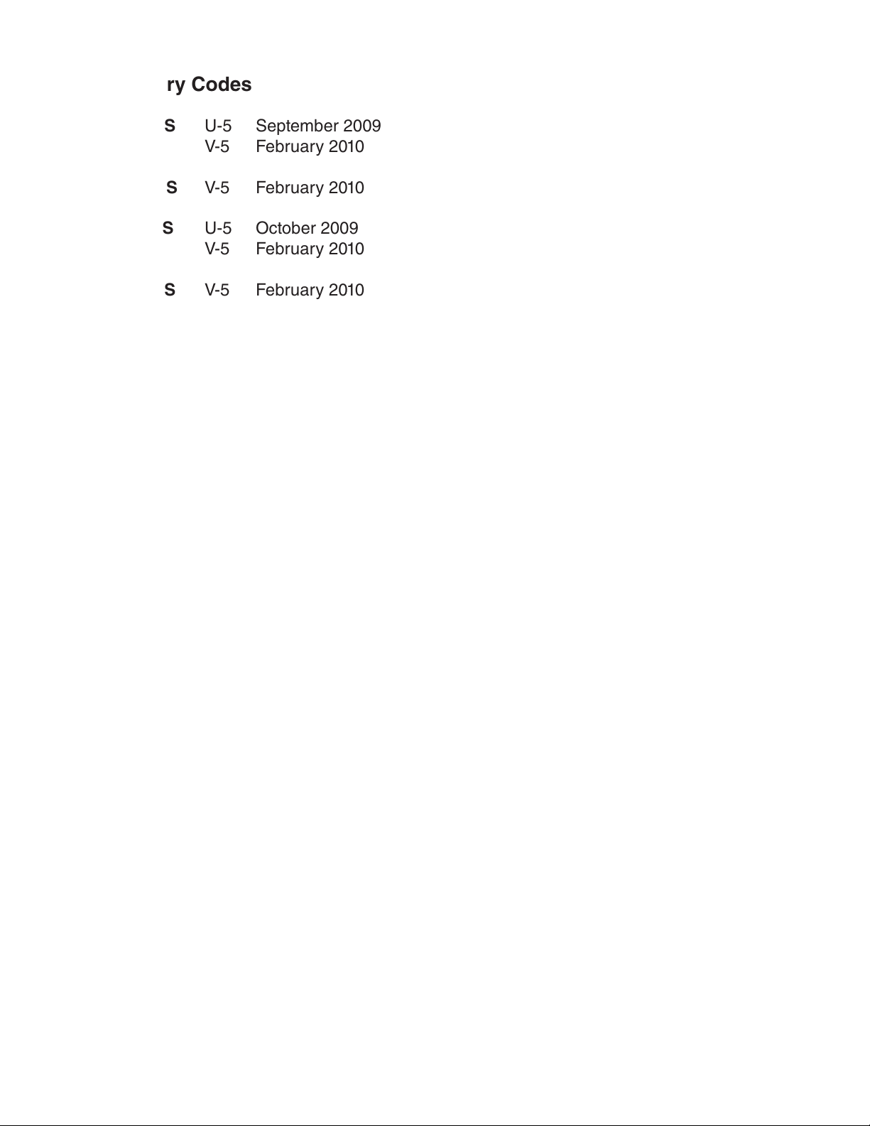
Auxiliary Codes
CR1A-FS U-5 September 2009
V-5 February 2010
CR1A-HS V-5 February 2010
CF1A-FS U-5 October 2009
V-5 February 2010
CF1A-HS V-5 February 2010
Auxiliary Code Breakdown
The auxiliary code is the rst two characters in the serial number. The rst character
indicates the year. Years progress or regress in alphabetical order. The series runs from
"A" through "V" and the letters "I" and "O" are skipped. The second character indicates
signicant part changes within a year. Base is "5" and this number advances for each
change.
Note About Ordering Parts
Most assemblies cannot be ordered as complete units; parts in the assemblies generally
must be ordered separately.
3
Page 4
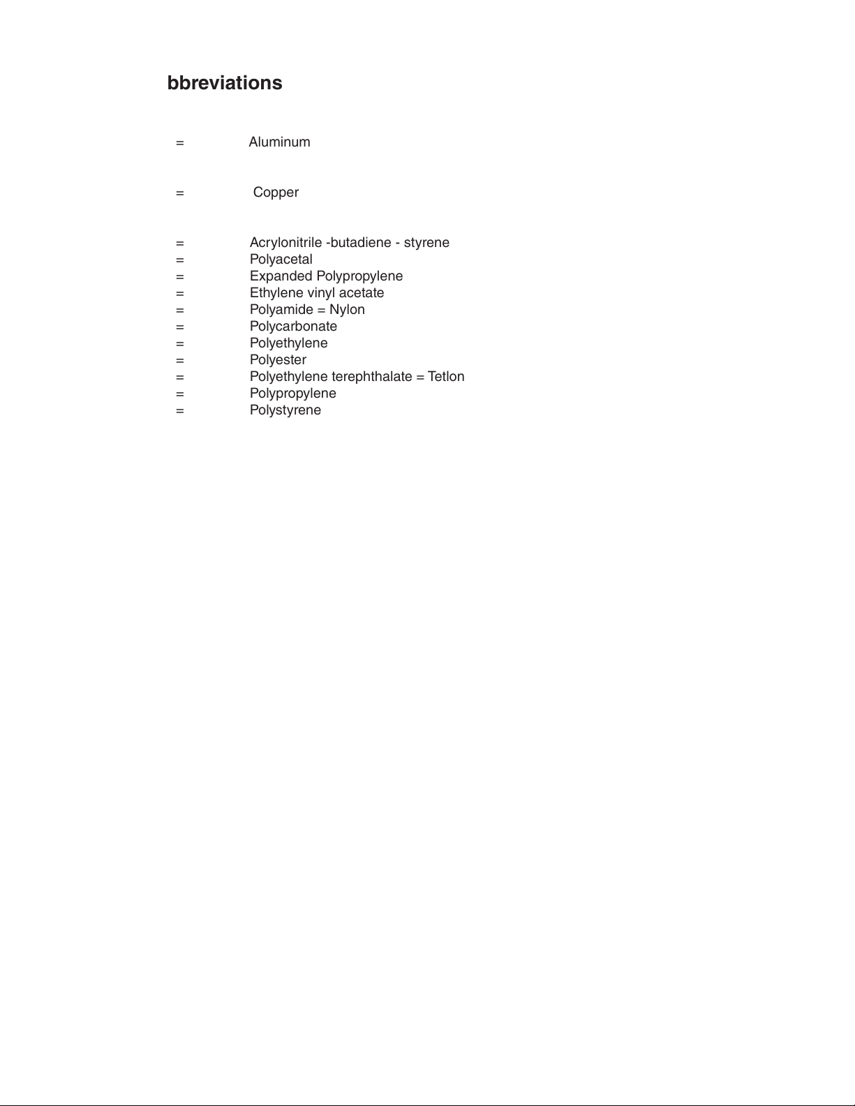
Material Abbreviations
ALUMINUM
AL = Aluminum
COPPER
CU = Copper
PLASTIC
ABS = Acrylonitrile -butadiene - styrene
AC = Polyacetal
EPP = Expanded Polypropylene
EVA = Ethylene vinyl acetate
PA = Polyamide = Nylon
PC = Polycarbonate
PE = Polyethylene
PES = Polyester
PETP = Polyethylene terephthalate = Tetlon
PP = Polypropylene
PS = Polystyrene
PTFE = Polytetrauoroethylene = Teon
PUR = Polyurethane
PVC = Polyvinyl chloride
RUBBER
EPDM = EP rubber
EPH = Epichlorohydrin
NBR = Nitrile butadiene rubber
NP = Neoprene
NR = Natural rubber
SI.R = Silicone rubber
SY.R = Synthetic rubber
VN = Vinyl Nitrile
STEEL
GS = Galvanized steel
PAS = Primed steel
PS = Plated steel
SS = Stainless steel
4
Page 5
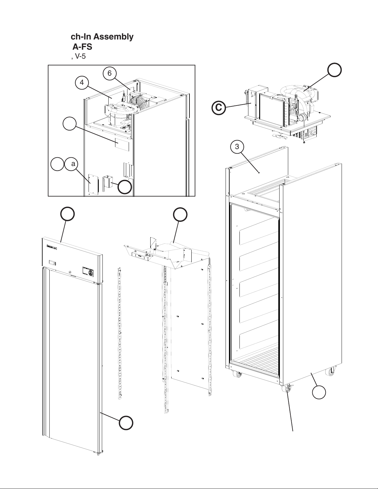
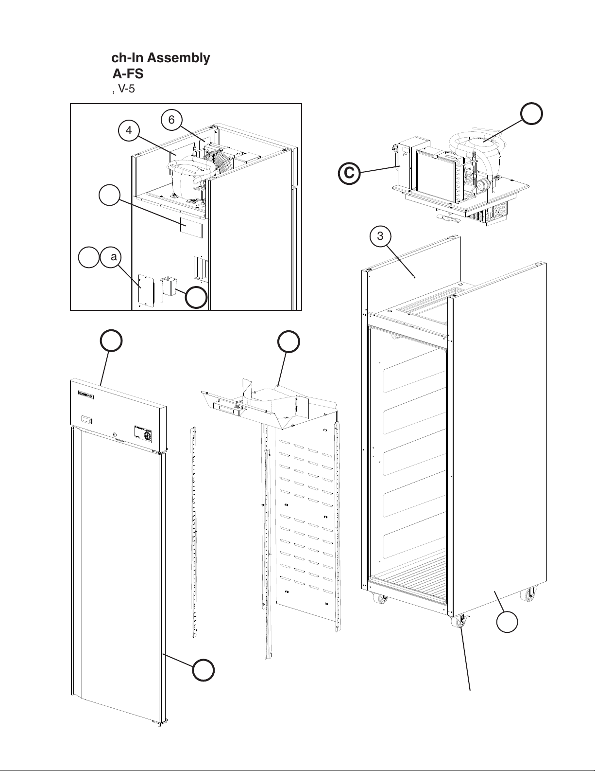
A. Reach-In Assembly
CR1A-FS
U-5, V-5
6
4
B
C
5
3
2a
2
D
E
F
G
1
For casters, see
section "H"
5
Page 6
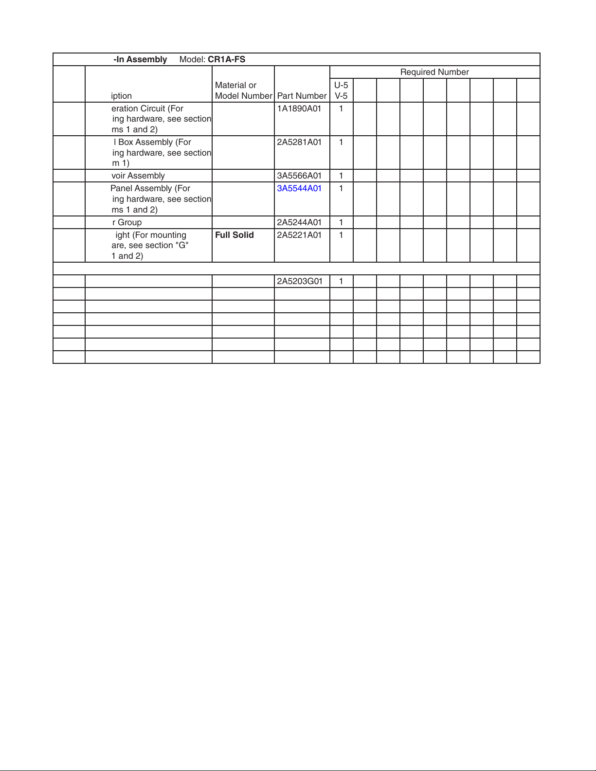
Title: A. Reach-In Assembly Model: CR1A-FS
Index
No. Description
B Refrigeration Circuit (For
mounting hardware, see section
"B" items 1 and 2)
C Control Box Assembly (For
mounting hardware, see section
"C" item 1)
D Reservoir Assembly 3A5566A01 1
E Front Panel Assembly (For
mounting hardware, see section
"E" items 1 and 2)
F Interior Group 2A5244A01 1
G Door-Right (For mounting
hardware, see section "G"
items1 and 2)
1 Body 2A5203G01 1
2 Reservoir Cover 3A5555-01 1
2a T2 Screw 4×8, SS 7P32-0408 2
3 Grounding Screw 5×8, BRASS 433304-02 1
4 Wiring Label 2A5335-01 1
5 Caution Label 4A1931-01 1
6 Nameplate 2A5306-01 1
Material or
Model Number Part Number
1A1890A01 1
2A5281A01 1
3A5544A01 1
Full Solid 2A5221A01 1
Required Number
U-5
V-5
6
Page 7
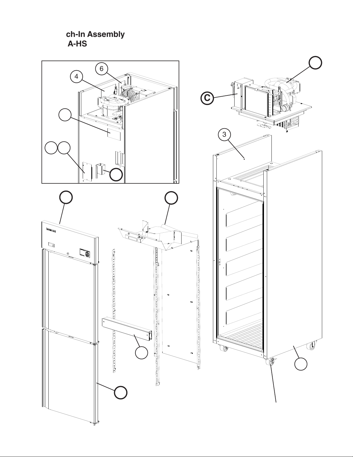
A. Reach-In Assembly
CR1A-HS
V-5
6
4
C
B
5
3
2a
2
D
E
F
G
7
1
For casters, see
section "H"
7
Page 8
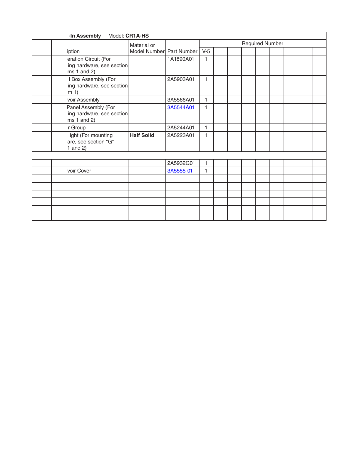
Title: A. Reach-In Assembly Model: CR1A-HS
Index
No. Description
B Refrigeration Circuit (For
mounting hardware, see section
"B" items 1 and 2)
C Control Box Assembly (For
mounting hardware, see section
"C" item 1)
D Reservoir Assembly 3A5566A01 1
E Front Panel Assembly (For
mounting hardware, see section
"E" items 1 and 2)
F Interior Group 2A5244A01 1
G Door-Right (For mounting
hardware, see section "G"
items1 and 2)
1 Body 2A5932G01 1
2 Reservoir Cover 3A5555-01 1
2a T2 Screw 4×8, SS 7P32-0408 2
3 Grounding Screw 5×8, BRASS 433304-02 1
4 Wiring Label 2A5335-01 1
5 Caution Label 4A1931-01 1
6 Nameplate 2A5306-02 1
7 Mullion 2A5350A01 1
Material or
Model Number Part Number
1A1890A01 1
2A5903A01 1
3A5544A01 1
Half Solid 2A5223A01 1
Required Number
V-5
8
Page 9
A. Reach-In Assembly
CF1A-FS
U-5, V-5
6
4
B
C
5
3
2a
2
D
E
F
G
1
For casters, see
section "H"
9
Page 10

Title: A. Reach-In Assembly Model: CF1A-FS
Index
No. Description
B Refrigeration Circuit (For
mounting hardware, see section
"B" items 1 and 2)
C Control Box Assembly (For
mounting hardware, see section
"C" item 1)
D Reservoir Assembly 3A5566A01 1
E Front Panel Assembly (For
mounting hardware, see section
"E" items 1 and 2)
F Interior Group 2A5344A01 1
G Door-Right (For mounting
hardware, see section "G"
items1 and 2)
1 Body 2A5865G01 1
2 Reservoir Cover 3A5555-01 1
2a T2 Screw 4×8, SS 7P32-0408 2
3 Grounding Screw 5×8, BRASS 433304-02 1
4 Wiring Label 2A5345-01 1
5 Caution Label 4A1931-01 1
6 Nameplate 2A5306-03 1
Material or
Model Number Part Number
1A1891A01 1
2A5346A01 1
3A5823A01 1
Full Solid 2A5221A01 1
Required Number
U-5
V-5
10
Page 11

A. Reach-In Assembly
CF1A-HS
V-5
6
4
5
2a
2
D
B
C
3
E
F
7
1
G
For casters, see
section "H"
11
Page 12

Title: A. Reach-In Assembly Model: CF1A-HS
Index
No. Description
B Refrigeration Circuit (For
mounting hardware, see section
"B" items 1 and 2)
C Control Box Assembly (For
mounting hardware, see section
"C" item 1)
D Reservoir Assembly 3A5566A01 1
E Front Panel Assembly (For
mounting hardware, see section
"E" items 1 and 2)
F Interior Group 2A5344A01 1
G Door-Right (For mounting
hardware, see section "G"
items1 and 2)
1 Body 2A5348G01 1
2 Reservoir Cover 3A5555-01 1
2a T2 Screw 4×8, SS 7P32-0408 2
3 Grounding Screw 5×8, BRASS 433304-02 1
4 Wiring Label 2A5345-01 1
5 Caution Label 4A1931-01 1
6 Nameplate 2A5306-04 1
7 Mullion 2A5350A01 1
Material or
Model Number Part Number
1A1891A01 1
2A5346A01 1
3A5823A01 1
Half Solid 2A5223A01 1
Required Number
V-5
12
Page 13

B. Refrigeration Circuit
1/2
CR1A-FS, CR1A-HS
U-5, V-5
34
2
1
20a
20
21
35 36
3
37
3a
7
8
37a
3c 3d
3b
5 6
4
10 11
9
38
23
22
22a
22b
13
Page 14

B. Refrigeration Circuit
2/2
CR1A-FS, CR1A-HS
U-5, V-5
33 34
27
27a
32
31
31a
26
26a
28
29
30
29a
19
19a
17
40
39
39a
12
42 43
12a
13
24
41
24a
25
14
15 16
14
18
18a
Page 15

Title: B. Refrigeration Circuit Model: CR1A-FS, CR1A-HS
Index
No. Description
1 Truss Head Screw 5×25, SS 7C32-0525 4
2 Washer 4A0655-03 4
3 Compressor NF5.5FX 4A3177-01 1
3a Screw 10×3 4A4993-01 4
3b Compressor Clip 4A4867-01 4
3c Rubber Grommet 4A1452-01 4
3d Compressor Mount Insert 4A4875-01 4
4 Terminal Cover (includes clip) 4A2141-01 1
5 Cord Relief 4A2152-01 2
6 Start Relay 4A2135-03 1
7 Start Capacitor 280MFD,
8 Condenser-Capillary Assembly
(items 9 through 11; order
assembly parts individually)
9 Drier 4A0924-01 1
10 Nylon Tie 8911-0300 1
11 Nylon Tie Mount 437618-01 1
12 Evaporator Assembly (items
12a through 18a; order
assembly parts individually)
12a Screw 4A4993-02 2
13 Evaporator 2A5183-01 1
14 Defrost Thermistor 4A4865-02 1
15 Thermistor Tie Clip 4A3248G01 1
16 Nylon Tie 8911-0150 1
17 Evaporator Bracket 3A5492-01 2
18 Evaporator Drain Bracket 3A5495-01 1
18a T2 Screw 4×8, SS 7P32-0408 4
19 Evaporator Mount Bracket 3A5493-01 2
19a Screw 4A4993-02 4
20 Evaporator Fan Assembly
(items 20a through 23; order
assembly parts individually)
20a Screw 4A4993-02 2
21 Fan Motor Bracket SS 4A4935-01 1
22 Evaporator Fan Motor 4A4942-01 1
22a Split Lock Washer No. 8, SS 7L22I0832 2
22b Hex Nut No. 8-33, SS 7N02I0832 2
23 Evaporator Fan Blade 4A4943-01 1
24 Condenser Assembly (items
24a through 31a; order
assembly parts individually)
24a Screw 4A4993-02 6
25 Condenser 2A5182-01 1
26 Condenser Shroud GS 2A5263-01 1
26a T2 Screw 4×8, SS 7P32-0408 6
Material or
Model Number Part Number
4A2134-01 1
125/165VAC
or120/150VAC
3A5674G01 1
2A5265G01 1
3A5590A01 1
2A5260A01 1
Required Number
U-5
V-5
15
Page 16

Title: B. Refrigeration Circuit Model: CR1A-FS, CR1A-HS
Index
No. Description
27 Condenser Fan Motor (includes
fan blade mounting bolt)
27a Self-Locking Nut No.8-32 7N21I0832 4
28 Condenser Fan Blade 3A5817-01 1
29 Condenser Fan Guard 2A5187-01 1
29a Truss Head Screw 5×12, SS 7C32-0512 4
30 Air Filter 3A0277-01 1
31 Air Filter Retainer SS 4A0790-02 1
31a T2 Screw 4×8, SS 7P32-0408 2
32 R-134a Label 444463-01 1
33 Process Assembly (1 of item
34; order assembly parts
individually)
34 Access Valve 457729-01 2
35 Condensate Pan Assembly
(items 36 through 39; order
assembly parts individually)
36 Condensate Pan 2A5218-01 1
37 Condensate Coil Strap 3A5672-01 1
37a T2 Screw 4×8, SS 7P32-0408 2
38 Condensate Coil Gasket 4A0455-04 1
39 Condensate Pump (includes
3mm ID × 625mm suction
hose and 6mm ID × 375mm
discharge hose)
39a T2 Screw 4×20, SS 7P32-0420 2
40 Capillary Tube/Suction Tube
(Heat Exchanger)
41 Refrigeration Circuit Base EPP 2A5184-01 1
42 Cable Tie Mount 437618-01 1
43 Nylon Tie 8911-0150 1
Material or
Model Number Part Number
4A4869-01 1
3A5597G01 1
2A5337A01 1
4A5111-01 1
2A5285G01 1
Required Number
U-5
V-5
16
Page 17

B. Refrigeration Circuit
1/2
CF1A-FS, CF1A-HS
U-5, V-5
35
2
1
21a
21
22
36 37
3
38
3a
8
38a
12
3b
9
3c 3d
10 11
39
24
23
23a
23b
17
Page 18

B. Refrigeration Circuit
2/2
CF1A-FS, CF1A-HS
U-5, V-5
34 35
28
28a
33
41
32a
32
27a
27
31
29
30a
30
25a
7
5 6
4
25
26
20
20a
19
16
18
18
18a
40
17
40a
15
17a
43 44
13a
13
42
14
Page 19

Title: B. Refrigeration Circuit Model: CF1A-FS, CF1A-HS
Index
No. Description
1 Truss Head Screw 5×25, SS 7C32-0525 4
2 Washer 4A0655-03 4
3 Compressor SC12CLX.2 4A3808-01 1
3a Screw 10×3 4A4993-01 4
3b Compressor Clip 4A4867-01 4
3c Rubber Grommet 4A1452-01 4
3d Compressor Mount Insert 4A4875-01 4
4 Terminal Cover 4A3112-01 1
5 Cord Relief 4A1454-01 2
6 Start Relay 4A3113-01 1
7 Start Capacitor 240MFD,
8 Condenser-Capillary Assembly
(items 9 through 12; order
assembly parts individually)
9 Drier 4A0924-01 1
10 Nylon Tie 8911-0300 1
11 Nylon Tie Mount 437618-01 1
12 Pressure Switch 4A2516-02 1
13 Evaporator Assembly (items
13a through 19; order assembly
parts individually)
13a Screw 4A4993-02 2
14 Evaporator 2A5183-01 1
15 Defrost Thermistor 4A4865-01 1
16 Evaporator Bracket 3A5492-01 2
17 Evaporator Drain Bracket 3A5495-01 1
17a T2 Screw 4×8, SS 7P32-0408 4
18 Defrost Thermostat 4A0954-02 1
18a T2 Screw 4×8, SS 7P32-0408 2
19 Defrost Heater 2A5378-01 1
20 Evaporator Mount Bracket 3A5493-01 2
20a Screw 4A4993-02 4
21 Evaporator Fan Assembly
(items 21a through 24; order
assembly parts individually)
21a Screw 4A4993-02 2
22 Fan Motor Bracket SS 4A4935-01 1
23 Evaporator Fan Motor 4A4942-01 1
23a Split Lock Washer No. 8, SS 7L22I0832 2
23b Hex Nut No.8-33, SS 7N02I0832 2
24 Evaporator Fan Blade 4A4943-01 1
25 Condenser Assembly (items
25a through 32a; order
assembly parts individually)
25a Screw 4A4993-02 6
26 Condenser 2A5182-01 1
Material or
Model Number Part Number
4A2134-03 1
125/165VAC
or120/150VAC
3A5786G01 1
2A5377G01 1
3A5590A01 1
2A5260A01 1
Required Number
U-5
V-5
19
Page 20

Title: B. Refrigeration Circuit Model: CF1A-FS, CF1A-HS
Index
No. Description
27 Condenser Shroud GS 2A5263-01 1
27a T2 Screw 4×8, SS 7P32-0408 6
28 Condenser Fan Motor (includes
fan blade mounting bolt)
28a Self-Locking Nut No.8-32 7N21I0832 4
29 Condenser Fan Blade 3A5817-01 1
30 Condenser Fan Guard 2A5187-01 1
30a Truss Head Screw 5×12, SS 7C32-0512 4
31 Air Filter 3A0277-01 1
32 Air Filter Retainer SS 4A0790-02 1
32a T2 Screw 4×8, SS 7P32-0408 2
33 R-404A Label 4A0960-01 1
34 Process Assembly (1 of item
35; order assembly parts
individually)
35 Access Valve 457729-01 2
36 Condensate Pan Assembly
(items 37 through 40; order
assembly parts individually)
37 Condensate Pan 2A5218-01 1
38 Condensate Coil Strap 3A5672-01 1
38a T2 Screw 4×8, SS 7P32-0408 2
39 Condensate Coil Gasket 4A0455-04 1
40 Condensate Pump (includes
3mm ID × 625mm suction
hose and 6mm ID × 375mm
discharge hose)
40a T2 Screw 4×20, SS 7P32-0420 2
41 Capillary Tube/Suction Tube
(Heat Exchanger)
42 Refrigeration Circuit Base EPP 2A5184-01 1
43 Cable Tie Mount 437618-01 1
44 Nylon Tie 8911-0150 1
Material or
Model Number Part Number
4A4869-01 1
4A5002G01 1
2A5375A01 1
4A5111-01 1
2A5347G01 1
Required Number
U-5
V-5
20
Page 21

C. Control Box Assembly
CR1A-FS, CR1A-HS, CF1A-FS, CF1A-HS
U-5, V-5
17
6
8a
8
5
10
4
7a
7
9a
9
18
15
16
20a
20
10
19
1
Title: C. Control Box Assembly Model: CR1A-FS, CR1A-HS, CF1A-FS, CF1A-HS
Index
No. Description
1 Screw 4A4993-02 2
2 Power Supply Cord 4A0520-01 1
3 Wire Clamp 4A0809-03 1
3a T2 Screw 4×8, SS 7P32-0408 1
4 Control Module (includes
mounting nut)
5 Display Cable 4A4863-01 1
6 Toggle Switch 4A0424-01 1
7 Door Switch Relay 418271-03 1
7a Tapping Screw 3×8 431415-01 2
8 Compressor Relay CF1A-_S 4A1307-01 1
8a Tapping Screw CF1A-_S
9 Terminal Block ESB2-323-424 4A2619-01 1
9a Tapping Screw 3×8 431415-01 2
10 Bushing OCB-875 428394-04 2
11 Plug Housing 3P 4A0425-01 1
12 Receptacle Housing 3P 4A0426-01 1
13 Plug Housing 6P 412832-03 1
14 Receptacle Housing 6P 412831-03 1
Material or
Model Number Part Number
CR1A-_S 4A4861-01 1
CF1A-_S 4A5101-01
431415-01 2
3×8
U-5
V-5
13
11
12
14
Required Number
2
3a
3
21
Page 22

Title: C. Control Box Assembly Model: CR1A-FS, CR1A-HS, CF1A-FS, CF1A-HS
Index
No. Description
15 Plug Housing CR1A-HS
16 Receptacle Housing CR1A-HS
17 Power Label 4A2196-01 1
18 Grounding Screw 433304-02 1
19 Control Box Base GS 2A5208-01 1
20 Control Box Cover GS 2A5209-01 1
20a T2 Screw 4×8, SS 7P32-0408 1
Material or
Model Number Part Number
412832-12 1
CF1A-_S
6P Red
412831-12 1
CF1A-_S
6P Red
U-5
V-5
Required Number
22
Page 23

D. Reservoir Assembly
CR1A-FS, CR1A-HS, CF1A-FS, CF1A-HS
U-5, V-5
3a
3
4
5
2
6
1
Title: D. Reservoir Assembly Model: CR1A-FS, CR1A-HS, CF1A-FS, CF1A-HS
Index
No. Description
1 Reservoir 3A5565-01 1
2 Float Switch 4A4937-01 1
3 Float Switch Bracket 3A5560-01 1
3a T2 Screw 4×8, SS 7P32-0408 1
4 Rubber Gasket 413854-03 1
5 Drain Fitting 4A2792-01 1
6 Silicone Hose L=150mm 7730I3812 1
Material or
Model Number Part Number
U-5
V-5
23
Required Number
Page 24

E. Front Panel Assembly
CR1A-FS, CR1A-HS, CF1A-FS, CF1A-HS
U-5, V-5
1
8
1
3
2
4
5 6
Title: E. Front Panel Assembly Model: CR1A-FS, CR1A-HS, CF1A-FS, CF1A-HS
Index
No. Description
1 T2 Screw 4×8, SS 7P32-0408 2
2 Truss Head Screw 5×10, SS 7C32-0510 2
3 Front Panel 2A5219-01 1
4 Display Module (includes
mounting clips)
5 Door Switch 3A1826-01 1
6 Door Lock Tumbler (includes
2keys)
7 Door Lock Cam 4A4925-01 1
8 Emblem 4A0560-01 1
9 Label-Commercial Series CR1A-_S 3A5816-01 1
Material or
Model Number Part Number
CF1A-_S 3A5816-02 1
7
U-5
V-5
4A4862-01 1
4A4924-01 1
9
Required Number
24
Page 25

F. Interior Group
CR1A-FS, CR1A-HS, CF1A-FS, CF1A-HS
U-5, V-5
4a
4
15
6
7a
7
CR1A-FS, CR1A-HS
CF1A-FS, CF1A-HS
2
14
13
1
5a
11
11a
12
5
3
3
10
8a
8
9
9
1
10
Title: F. Interior Group Model: CR1A-FS, CR1A-HS, CF1A-FS, CF1A-HS
Index
No. Description
1 Cabinet Thermistor 4A4864-01 1
2 Bushing CR1A-_S
3 Twist Wire Tie 4A5113-01 1
4 Evaporator Fan Shroud 3A5543G01 1
4a Truss Head Screw 5×10, SS 7C32-0510 7
5 Fan Guard 4A4860-01 1
5a T2 Screw 4×10, SS 7P32-0410 2
6 Fan Shroud 2A5291-01 1
7 Evaporator Shroud 3A5494-01 1
7a T2 Screw 4×8, SS 7P32-0408 4
Material or
Model Number Part Number
428394-02 1
OCB-500
U-5
V-5
25
Required Number
Page 26

Title: F. Interior Group Model: CR1A-FS, CR1A-HS, CF1A-FS, CF1A-HS
Index
No. Description
8 Pilaster 3A0145-22 4
8a Truss Head Screw 5×10, SS 7C32-0510 12
9 Rear Duct Panel CR1A-_S 2A5205-21 1
10 Duct Stand Off 4A4874-01 6
11 Incandescent Light Assembly
(items 11a through 15; order
assembly parts individually)
11a Truss Head Screw 5×10, SS 7C32-0510 2
12 Light Plate 3A5496-21 1
13 Light Socket 4A4443-01 1
14 Light Bulb 4A4444-01 1
15 Warning Label 4A2968-03 1
Material or
Model Number Part Number
CF1A-_S 2A5205-22 1
3A5564A01 1
U-5
V-5
Required Number
26
Page 27

G. Door-Right
Full Solid: CR1A-FS, CF1A-FS
U-5, V-5
1
3
2
7
5
7
6
7
1
Title: G. Door-Right Model: Full Solid: CR1A-FS, CF1A-FS
Index
No. Description
1 Truss Head Screw 5×10, SS 7C32-0510 6
2 Split Lock Washer M5, SS 7L22-0500 6
3 Hinge Bracket (R) 3A5542G01 2
4 Hinge Collar 339948-01 1
5 Door Subassembly (includes
item6)
6 Door Gasket 2A5192-01 1
7 Truss Head Screw (ller) 5×10, SS 7C32-0510 8
Material or
Model Number Part Number
2A5220G01 1
27
4
3
2
Required Number
U-5
V-5
Page 28

G. Door-Right
Half Solid: CR1A-HS, CF1A-HS
V-5
7
8a
8
7
1
3
2
6
5
4
7
Title: G. Door-Right Model: Half Solid: CR1A-HS, CF1A-HS
Index
No. Description
1 Truss Head Screw 5×10, SS 7C32-0510 8
2 Split Lock Washer M5, SS 7L22-0500 8
3 Hinge Bracket (R) 3A5542G01 3
4 Hinge Collar 339948-01 2
5 Door Subassembly (includes 1
of item6)
6 Door Gasket 2A5192-02 2
7 Truss Head Screw (ller) 5×10, SS 7C32-0510 11
8 Door Latch 4A4934-01 1
8a Screw-Bolt 5×16, SS 449879-08 1
Material or
Model Number Part Number
2A5222G01 2
V-5
1
3
2
6
5
4
1
3
2
Required Number
28
Page 29

H. Accessories & Packaging
CR1A-FS, CR1A-HS, CF1A-FS, CF1A-HS
U-5, V-5
2
Shelf Kit
Includes 3 shelves
and 12 clips
5a
5
Title: H. Accessories & Packaging Model: CR1A-FS, CR1A-HS, CF1A-FS, CF1A-HS
Index
No. Description
1 Instruction Manual 91A3KE10A 1
2 Shelf Kit (3 Pack) (includes
items 3 and 4)
3 Shelf 3A1387-01 3
4 Shelf Clip 428957-01 12
5 4-Inch Locking Caster 4A4275-01 2
5a Hex Head Tapping Bolt 1/4×20×1/2 7B03I1412 8
6 4-Inch Non-Locking Caster 4A4275-02 2
6a Hex Head Tapping Bolt 1/4×20×1/2 7B03I1412 8
3
4
6a
6
Material or
Model Number Part Number
HS-3508 3A1416A03 1
U-5
V-5
Required Number
- Packaging CR1A-FS 2A5302A01
CR1A-HS 2A5303A01
CF1A-FS 2A5304A01
CF1A-HS 2A5305A01
29
 Loading...