

Hosen MH LED 60D User Manual
User Manual
LED MOVING HEAD
MH LED 60D
Please Read over this Manual before Operating the Light Fixture

1.BeforeyouBegin .......................................................................................1
What is Included ...................................................................................................................1
Unpacking Instructions ..........................................................................................................1
Text Conventions ...................................................................................................................1
Icons ...................................................................................................................................1
Safety Notes .........................................................................................................................2
Expected LED Lifespan .......................................................................................................... 2
2. Introduction ..............................................................................................3
Feature Description .....................................................................................................................3
Features.......................................................................................................................................3
Additional Features....................................................................................................................3
DMX Channel Summary ................................................................................................................3
Product Overview .........................................................................................................................4
3.Setup .........................................................................................................5
AC Power................................................................................................................................5
AC Plug ...............................................................................................................................5
Fuse Replacement................................................................................................................5
Gobo Replacement ................................................................................................................6
LED Replacement...................................................................................................................6
DMX Linking .........................................................................................................................6
DMX Modes ........................................................................................................................6
Master/Slave Linking .............................................................................................................6
Mounting .............................................................................................................................. 7
Orientation .........................................................................................................................7
Rigging ...............................................................................................................................7
4. Operation .................................................................................................8
Control Panel Description ......................................................................................................8
Control Options .................................................................................................................... 8
Programming ........................................................................................................................8
DMX Operation ..................................................................................................................8
Stand-alone Operation........................................................................................................8
Master/Slave Operation ......................................................................................................8
Display Mode .....................................................................................................................8
Software Version ................................................................................................................8
Keylock .............................................................................................................................9
Movement Inversion ...........................................................................................................9
Color Wheel Movement .......................................................................................................9
Edit Custom .......................................................................................................................9
Range Limitation.................................................................................................................10
Move-in Black .....................................................................................................................10
Reset Control.....................................................................................................................10
System Default ...................................................................................................................10
Menu Map ......................... ....... ...... ....................................................................................11
DMX Values ..........................................................................................................................12
ADVANCED........................................................................................................................12
ADVANCED (Cont.) ............................................................................................................13
BASIC ...............................................................................................................................13
BASIC (Cont.) ....................................................................................................................14
5. Technical Information...............................................................................15
General Maintenance ..................................................................................................................15
Troubleshooting Guide........... ...... ...... ...... .................................................................................16
Exploded View .............................................................................................................................17
Tableof Contents

Parts List .............................................................................................................................18
Photometrics ........................................................................................................................18
Returns Procedure ...............................................................................................................19
Claims .................................................................................................................................19
Technical Specifications........................................................................................................ 20
6. Appendix................................................................................................... 21
DMX Primer ......................................................................................................................... 21
The Physical Medium............................................................................................................ 21
The Signals ......................................................................................................................... 21
The Functions ......................................................................................................................21
DMX Configuration ................................................................................................................21
Personalities ....................................................................................................................... 21
Starting Address .................................................................................................................. 21
Assigning Addresses ............................................................................................................22
DMX Universes ....................................................................................................................22
DMX Connectivity .................................................................................................................22
Fixture Location ...................................................................................................................22
Number of Fixtures ............................................................................................................... 22
DMX Data Cabling ................................................................................................................ 22
Making your Own DMX Cable................................................................................................. 22
DMX Cable Characteristics ....................................................................................................22
DMX Cable Connectors ........................................................................................................ 23
3-Pin to 5-Pin Conversion Chart ............................................................................................ 23
DMX Connection.................................................................................................................. 23
Master/Slave Linking ............................................................................................................. 24
Master/Slave Connection .....................................................................................................24
ID Addressing .......................................................................................................................25
Single Row Connection......................................................................................................... 25
Standard Block Connection .................................................................................................. 25
Repeated Row Block Connection .......................................................................................... 25
Other Effects .......................................................................................................................25
Sizing the Circuit Breakers .....................................................................................................26
Using the Spec Sticker..........................................................................................................26
Using the Watts/Volts Method................................................................................................ 26
Considering the Power Factor ............................................................................................... 26
Using the Volt Amps Method ..................................................................................................26
Selecting the Circuit Breaker ................................................................................................ 26
1. Before you Begin
What is
Included
Unpacking
Instructions
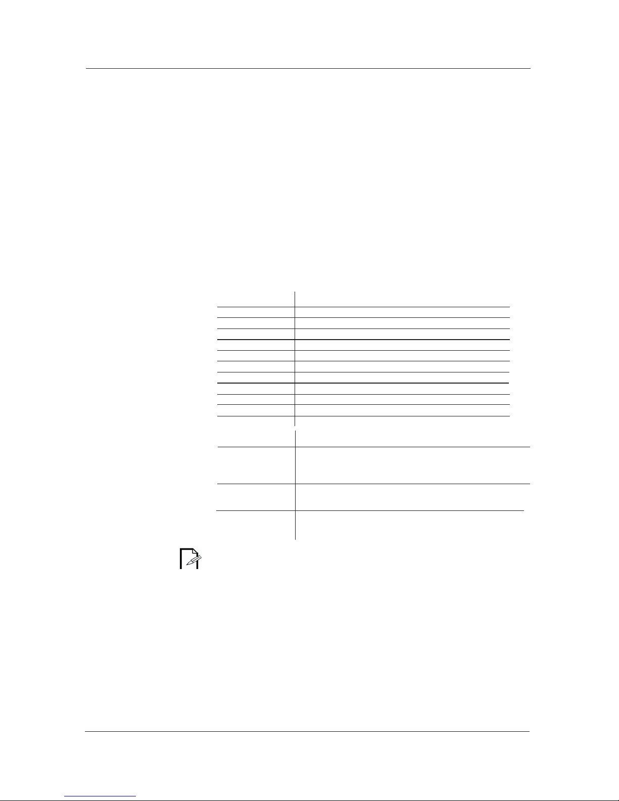
Text
Conventions
Conve nt ion Meaning
1~512
50/60
[10]
Claims
<SET>
Settings
MENU > Settings
[1~10]
Yes/No
ON
“COLORado™ UM ™”
A range of values
A set of mutually exclusive values in the text
A DIP switch to be configured
A fixture function, a new term, a section or a chapter
The name of another publication or manual
A button to be pressed on the fixture's control pan
A menu option that can be selected but not modified
A sequence of menu options to be followed
A range of menu values of which one can be selected
A set of mutually exclusive menu options to choose
A value to be entered
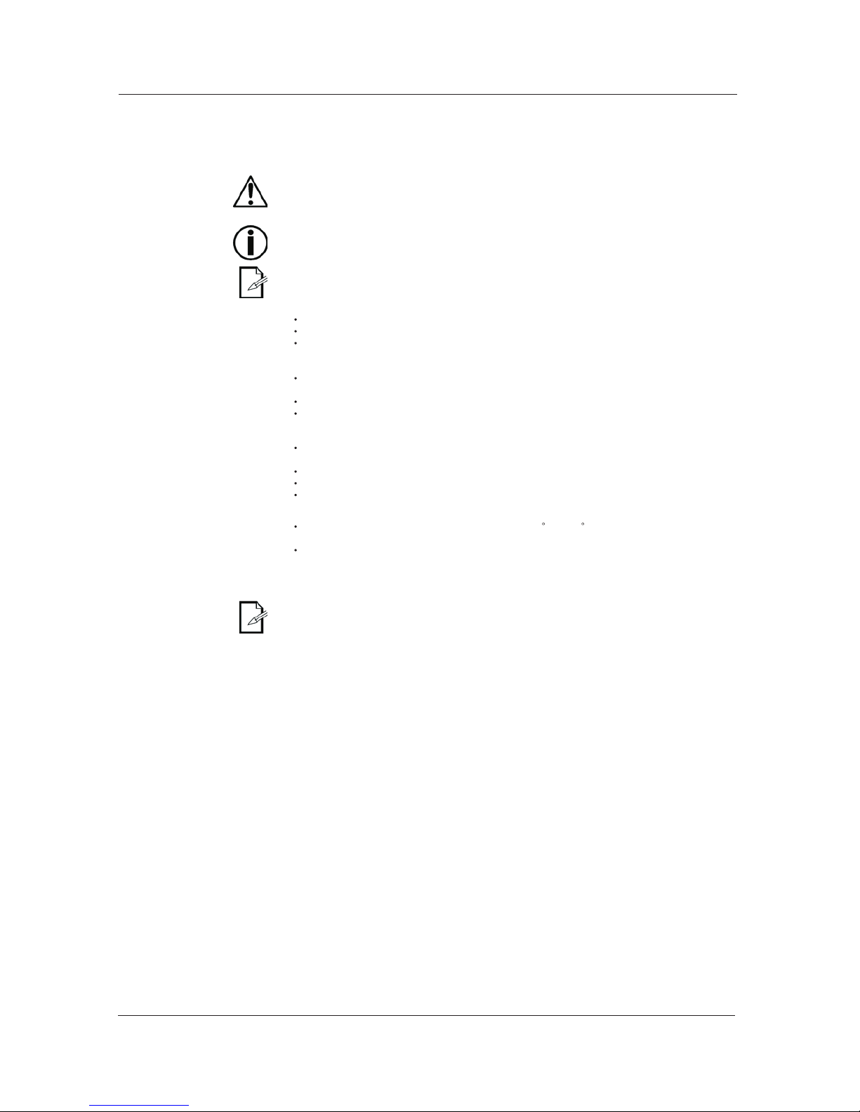
Icons
Icons Meani ng
The te rm “ DMX” used throughout t his document refers t o the USITTD MX512-A
transmission protocol
• One LED Moving head Light
• One power cord with plug
• Two mounting brackets
• Quick Reference Guide
This icon indicates useful, although non-critical information.
This icon indicates important installation or configuration in
formation. Failure to comply with this information may prevent
the fixture from functioning correctly.
This icon indicates critical installation, configuration or operation
information. Failure to comply with this information may render
the fixture partially or completely inoperative, damage thirdparty equipment, or cause harm to the user.
Immediately upon receiving a fixture, carefully unpack the box. Check the box contents
to ensure that all parts are present and that they are in good condition. If any part
appears damaged from shipping, or if the box shows signs of mishandling, notify the
shipper immediately. In addition, retain the box and all the packing material for
inspection.
In any event, save the carton and all packing material because, in case that you have
to return the fixture to the factory, you will have to do so in its original box, with its
original packing. See the Claims section in the Technical Information chapter.
--1--
Safety
Notes
Operation
Expected LED
Lifespan
Please read the following notes carefully because they include important
safety information about the installation, usage and maintenance of this product.
It is important to read all these notes before starting to work with this product.
There are no user serviceable parts inside the light. Any reference to servicing this unit
you may find from now on in this User Manual will only apply to properly C we certified
technicians. Do not o pen the housing or attempt any repairs unless you are one of them.
Please refer to all applicable local codes and regulations for proper installation
of the light.
Keep this manual for future consultation. If you sell the light to another user, make
sure that they also receive this manual.
Personal
Safety
Mounting
and Rigging
Power
and Wiring
Avoid direct eye exposure to the light source while the fixture is on.
Always disconnect the light from its power source before servicing.
Always connect the light to a grounded circuit to avoid the risk of electrocution.
This product is for indoor use only! To prevent risk of fire or shock, do not expose
this product to rain or moisture.
Make sure there are no flammable materials close to the fixture(s) while operating.
When hanging this fixture, always secure it to a fastening device using a safety
cable (not provided).
Always make sure that you are connecting the light to the proper voltage, as per the
specifications in this manual or on the product's sticker.
Never connect the light to a dimmer pack.
Make sure that the power cable is not cracked, crimped or damaged.
Never disconnect the fixture by pulling or tugging on the power cable.
The maximum ambient temperature (Ta) is 104 F (40 C). Do not operate the
fixture at a higher temperature.
In case of a serious operating problem, stop using this product immediately!
In t he unlikely e vent t hat your light may require ser vice, please contact our Technical
Support.
LEDs gradually decline in brightness over time, mostly because of heat. Packaged in
clusters, LEDs exhibit higher operating temperatures than in ideal or singular optimum
conditions. For this reason, using all color .LEDs at their fullest intensity significantly
reduces the LEDs' lifespan. Under normal conditions, this lifespan can be of 40,000 to
50,000 hours. If extending this lifespan expectancy is vital, lower the operational
temperature by improving ventilation and reducing the external temperature , as well
as limiting the overall projection intensity
--2--
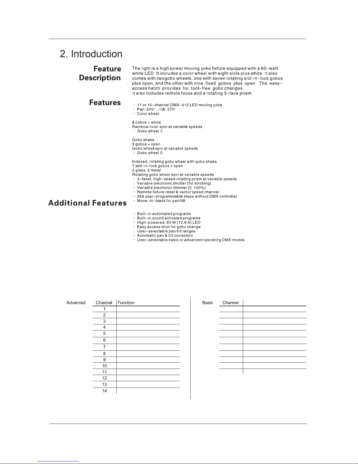
DMX Channel Summary
Function
Pan 1 Pan
Pan Fine 2 Tilt
Tilt 3 Color Wheel
Tilt Fine 4 Fixed Gobo Wheel (#1)
Pan / Tilt Speed
5 Rotating Gobo Wheel (#2)
Color Wheel
6 Gobo Rotation
Fixed Gobo Wheel (#1)
7 Rotating Prism
Rotating Gobo Wheel (#2) 8 Focus
Gobo Rotation 9 Dimmer
Rotating Prism 10 Strobe
Focus 11 Control
Dimmer
Strobe
Control
--3--
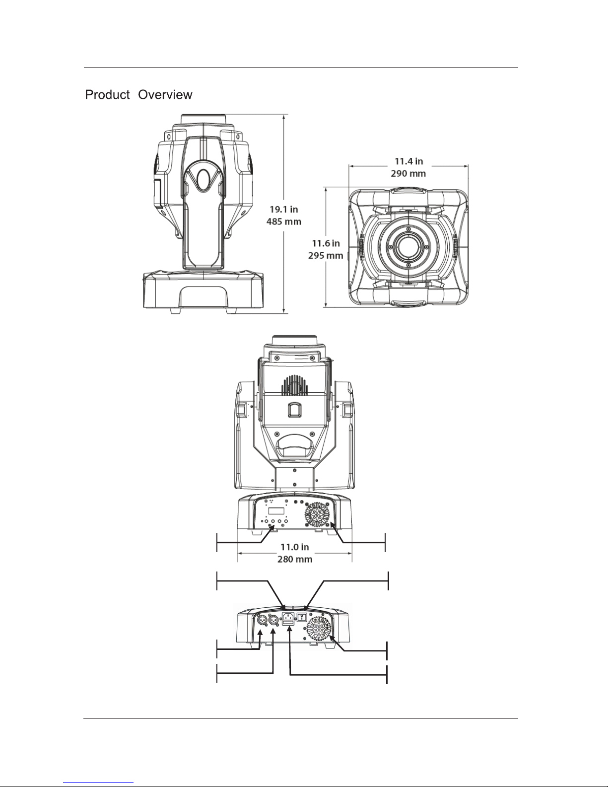
Product Dimensions Drawing Here
Base Fan
Fuse Holder
Control Panel
Base Fan
DMX Out
DMX In
Power Input On/Off Switch
--4--
3. Setup
AC Power
The light has an auto-ranging power supply that can work with an input voltage range
of 100~240 VAC, 50/60 Hz.
Make sure that you are connecting this product to the proper voltage, as per the
specifications in this guide, the product's user manual or on the product's sticker.
AC Plug
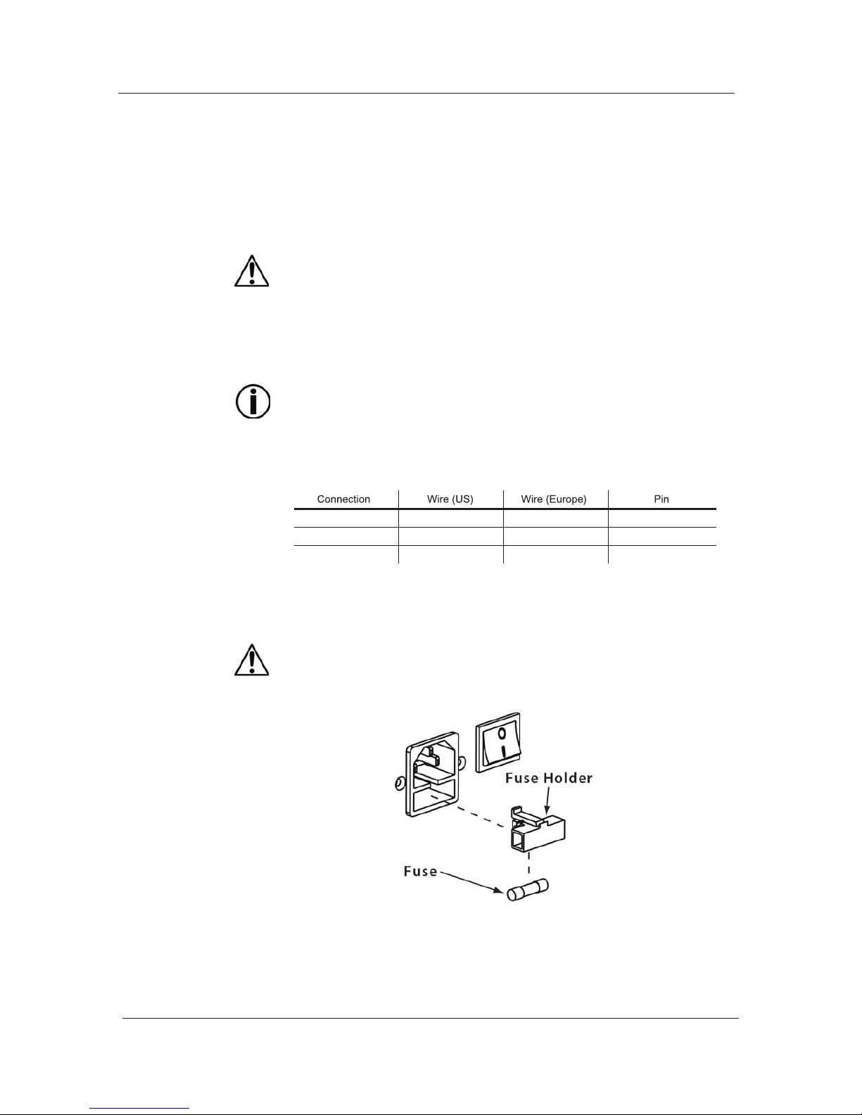
AC Live Black Brown 1
AC Neutral White Blue 2
3
Fuse Replacement
Always connect the light to a protected circuit with an appropriate
electrical ground to avoid the risk of electrocution or fire.
To determine the power requirements for the light see the label affixed to the side of
the fixture. Alternatively, you may refer to the technical specifications chart in the
Technical Information chapter of this manual.
The listed current rating indicates the maximum current draw during normal operation.
Please refer to the Sizing the Circuit B reakers section in the Appendix chapter of this
manual.
Never c onnect the light to a r heostat ( variable r esistor) or dimmer circuit,
even if the rheostat or dimmer channel serves only as a 0 to 100% switch.
The light comes with a power input cord terminated with an IEC connector on one end
an Edison plug on the other end (US market). If the power cord that came with your fixture
has no plug or you need to change the Edison plug, use the tablebelow to wire the new plug
AC Ground Green/Yellow Green/Yellow
1) With a flat head screwdriver, wedge the fuse holder out of its housing and remove
the blown fuse from the holder.
2) Replace the blown fuse with a fuse of the exact same type and rating.
3) Insert the fuse holder back in its place, and reconnect power.
Make sure to disconnect the fixture's power cord before replacing a blown fuse,
and always replace it with a fuse of the same type and rating.
--5--
Gobo
Replacement
LED
Replacement
1) Unlock the gobo cover and slide it away.
2) Take the target gobo out of the gobo wheel.
3) Install the new rotating gobo.
4) Slide and lock the gobo cover.
Make sure to disconnect the fixture's power cord before replacing the gobo.
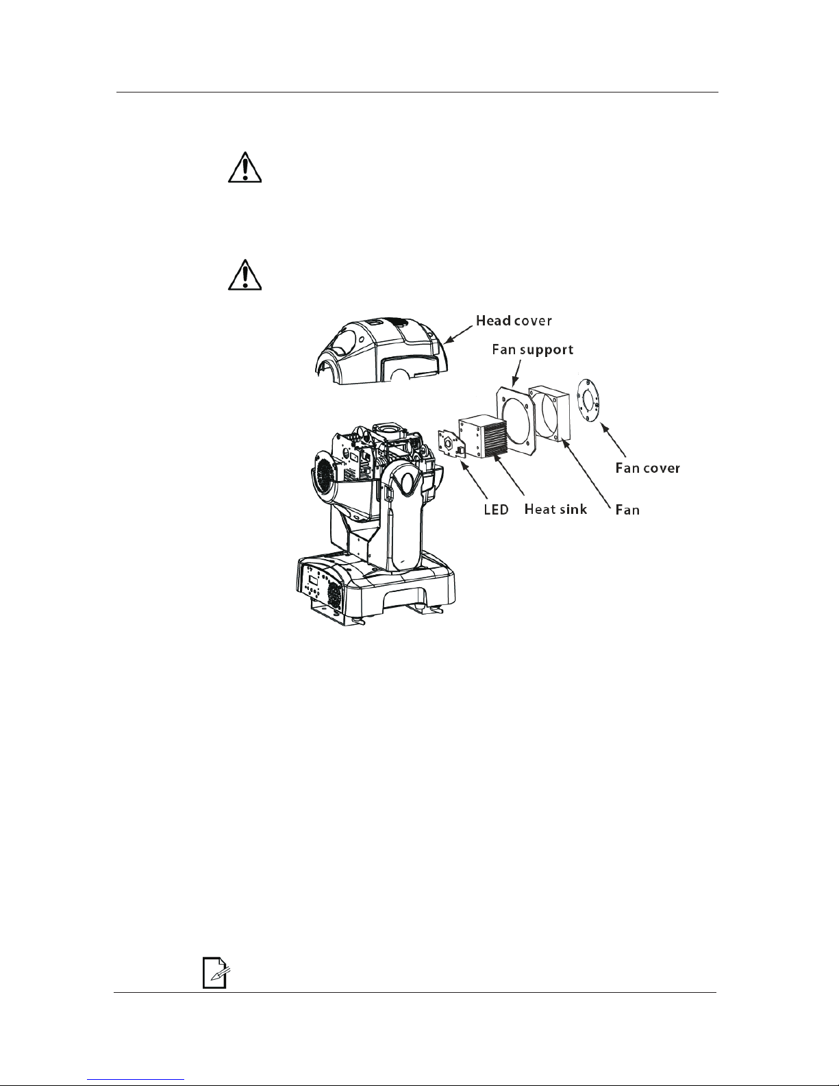
1) Remove the head cover by loosening its screws.
2) Remove the fan cover, the head fan, the fan support and the heat sink in this order.
3) Disconnect and remove the LED.
Mount and connect the new LED.
5) Reverse steps "2" and "1".
Make sure to disconnect the fixture's power cord before replacing the LED.
DMX Linking
DMX Modes
Master/Slave
Linking
You may link the light to a DMX controller using a standard DMX serial connection. If using
other DMX compatible fixtures with the light, it is possible to control them individually with a
single DMX controller.
It is also possible to run several DMX compatible fixtures synchronized without a DMX
controller in a master/slave operating mode.
If you are not familiar with the DMX standard, please refer to the DMX Primer and
DMX Connectivity sections in the Appendix chapter of this manual.
The light uses the standard DMX data connection for its DMX modes, Advanced and
Basic. Refer to the Operation Instructions chapter to learn how to configure the light
to work in these modes. The DMX Values section will give you detailed information
regarding the above-mentioned DMX modes.
The Master/Slave mode allows a fixture (the master) running a preconfigured
program to control several other fixtures (the slaves) without requiring a DMX
controller. In this mode, all the slave fixtures will operate in
unison with the master fixture.
When in Master/Slave mode, the units link to each other using the standard DMX
connection.
If you are not familiar with the Master/Slave connectivity, please refer to the DMX
Primer and DMX Connectivity sections in the Appendix chapter of this manual.
The Operation chapter of this manual provides detailed instructions on how to
configure the Master and Slave units.
--6--
 Loading...