Horton ICU Installation Manual

5 (1)
Horton ICU Installation  Manual

Corpus Christi, Texas

GENERAL INSTALLATION


® 4242 Baldwin Boulevard


USA 78405-3399

MANUAL DOORS - ICU / CCU


Tel: 800-531-3111, 361-888-5591


Fax: 800-531-3108, 361-888-6510

Profiler-ICU®

A9.2

www.hortondoors.com

Typical Framing and Bottom Guides

Jan 08

A U T O M A T I C S The Automatic Choice


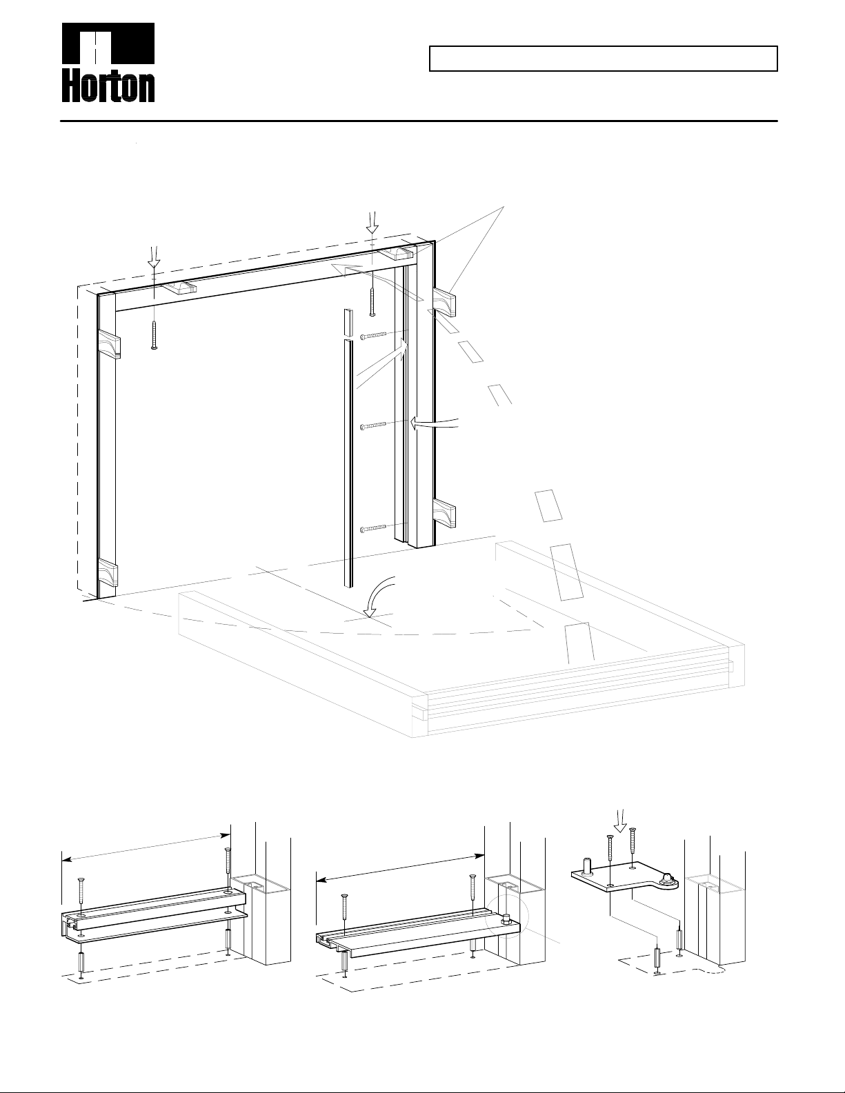
Typical Perimeter Mount Frame Installation


in. )


s m


ce


w

( 2 pla


cre


l S


eta


t M


ee


d

Sh


ea


-H


ex


" H


4

x 1 1/2


h

#1


d

wit


re


cu


er

se


ad


He


Door opening should allow for 1/4" ( 6mm ) minimum shim space at jambs and header. This allows for level & plumb installation.


b

m

Ja

et

ck

Po


ler

Fil


Provide rigid support, i.e. wood or metal studding

(or standard curtainwall min 1/8" thick) to allow Horton header and jambs to be secured as shown. Fasteners provided by factory. Alternate fasteners provided by authorized Horton installer.

Standard Horton slide door units are self-supporting and tie into adjacent construction for lateral stabillty. Adjacent structure must nor exceed deflection ratio of 1/8" per 16'-0" span. Excess deflection can cause adjacent structure to bear down on Horton unit and compromise slide movement and general functionality.


w


h


cre


l S


d

wit


eta


re


t


cu


ee


b

se


d

Sh


m


ea


Ja


-H


an


10 x


" P


b )


2 1/2


#


m


h

Ja


etd


ac


ck


. e


po


lcs


n-


(3

P


e

no


es us


rew


ag


ck


d

sc


d

pa


ea


ate


t-H


e R


h

Fla


ok


m


d

wit


: S


te


re


o


cu


N


d

are se


bs an


jam


r


de


or

un


y


ish Flo


in


wa

F


-a


ak


nd Bre


r a


"

oo


D


d

1/4


ee


xc


t e


a

no


l.


are


ve


f le


t o


ou


Typical Bottom Guide and Floor Pivot Installation

Floor pivots and bottom guides will vary with the unit type. The basic types are


ith


d w


re


cu


ts

se


w


o


re


d

piv


c


l S


es

an


eta


t M


uid


ee


l g


d

Sh


ica


yp


ea


T


-H


lat


" F


r


10 x 1 1/2


#


ho


nc


c a


sti


h

pla


wit


shown below.


e


elit


idth as Sid


e

W


m


e

Sa


elit


idth as Sid


e

W


m


Sa


Types 010 & 110

Type 310

Floor Mounted Bottom Guides

Floor Pivot for Trackless Units


Horton Automatics reserves the right to improve the product and change its specifications

CAD file 3.0181d

without notice. Dimensions given in U.S. Inches followed by Millimeters in parenthesis.

Loading...